國 立 交 通 大 學
電機學院 電信學程
碩士論文
在無線隨意網上提供語音/數據服務之高節能效率媒體存取層協定
Energy-efficient MAC protocol for
Voice/Data over Ad Hoc Networks
研 究 生:張建忠
指導教授:李程輝 教授
在無線隨意網上提供語音/數據服務之高節能效率媒體存取層協定
Energy-efficient MAC protocol for
Voice/Data over Ad Hoc Networks
研 究 生:張建忠 Student:Chien-Chung Chang
指導教授:李程輝 教授 Advisor:Tsern-Huei Lee
國 立 交 通 大 學
電機學院 電信學程
碩 士 論 文
A ThesisSubmitted to College of Electrical and Computer Engineering National Chiao Tung University
in partial Fulfillment of the Requirements for the Degree of
Master of Science in
Communication Engineering January 2009
Hsinchu, Taiwan, Republic of China
在無線隨意網上提供語音/數據服務之
高節能效率媒體存取層協定
學生:張建忠 指導教授
:李程輝 教授
國 立 交 通 大 學 電 機 學 院 電 信 學 程 碩 士 班
摘
要
為了延長使用電池供電無線網路設備之運轉時間,IEEE 802.11訂定了標準的
同步式電源管理機制。由於工作站間彼此的時間必需同步化,因此在IEEE
802.11標準中有針對IBSS(Independent Basic Service Set)規定一套分
散式同步電源管理機制TSF(Time Synchronous Function),以達到不需外
加同步設備即可達到同步的目的。
在IEEE 802.11 電 源 管 理 機 制 中 , 時 間 是 被 切 割 成 一 段 段 的 Beacon
Interval,在每個Beacon Interval的起始段,每個工作站都必須醒來一段
固定時間稱為ATIM Window,在這段時間裡如果工作站沒有資料要傳送或接
收,將會在Data transmission Window時進入睡眠狀態,從許多研究顯示
ATIM Window大小對MAC層省電效率及整體網路的效率有相當大的影響。
本論文設計一可以提供語音/數據之高節能效率媒體存取協定並提供
服務品質保證。我們將使用頻寬保留機制在語音傳送上,一但工作站在
ATIM Window中成功完成ATIM 訊息交握,工作站將不必要在ATIM Window中
競爭發送ATIM 訊息,即可在Data transmission Window中傳送語音封包。
本論文也提出可隨負載流量動態調整ATIM Window 大小的方法,並且改善
頻道使用率。本論文也同時讓工作站僅需要在Data transmission Window
中傳送資料時醒來,以減少工作站醒來時間及切換次數。
Energy-efficient MAC protocol for
Voice/Data over Ad Hoc Networks
student:Chien-Chung Chang Advisors:Dr. Tsern-Huei Lee
Degree Program of Electrical and Computer Engineering
National Chiao Tung University
Abstract
To prolong the network operating time of battery-powered wireless LAN devices, this work
proposes a synchronized power management scheme specified in IEEE 802.11 standard. The
proposed synchronous protocol requires precise time synchronization among all participating
nodes within the Independent Basic Service Set (IBSS). Therefore, Time Synchronization
Function (TSF) is defined to enable the protocol to operate without external timing sources. In
the proposed 802.11 power management scheme, time is divided into so-called beacon intervals.
At the start of each beacon interval, each node must stay awake for a fixed time-period called an
ATIM window (Ad-Hoc Traffic Indication Map window). Nodes that have no data to send or
receive during the ATIM window enter the doze state in the data transmission window. Many
studies indicate that ATIM window size significantly affects power saving and throughput
achieved by the nodes. This thesis introduces an energy-efficient t MAC protocol to support
CBR Voice and Data. Overall Quality of service (QOS) is guaranteed. A bandwidth reservation
scheme can be used for CBR Voice transmission. Once stations finish the ATIM message
exchange in ATIM window, stations transmit CBR Voice packets in the Data transmission
window without further ATIM contention. The proposed protocol improves bandwidth
utilization to dynamically adjust ATIM window length to the traffic load. Stations are also
allowed to stay awake for only a fraction of the Data window which reduces switch-over time in
Acknowledgement
I am deeply grateful to my academic advisor, Professor Tsern-Huei Lee, for invaluable guidance and constant encouragement. The research could not be completed without his valuable assistance.
Professor Jui-Teng, Wang of Graduate Institute of Communication Engineering, National Chi Nan University, and Professor Yaw-Wen, Kuo of Graduate Institute of Communication Engineering, National Chi Nan University are appreciated for their valuable opinions, which have substantially improved this thesis.
I am also grateful to the PhD candidates, Jing-Rong Hsieh, and Yu-Wen Huang in the Network and Telecommunication Laboratory (NTL), Department of Communication Engineering, National Chiao Tung University, for their valuable opinions.
I appreciate the Chief of EMC, Network operation &Maintenance Dept. in Northern Taiwan Business Group of Chunghwa Telecom Co., Ltd, Pin-Chih Huang, Chiu-Lun Lin, who has been very supportive during my masters’ studies. I also would like to thank Hao-Wen Sun, Chien-Tai Tsai, Chi-Lu Kuo, Deng-Tai Hu and other colleagues for their valuable help.
Finally, I am deeply grateful to my wife and my daughter and son for their continuing encouragement, understanding and patience in our daily life. I thank my mother for raising me up with her great maternal love.
Contents
Chapter 1 Introduction ...1
1.1 Motivation ...4
1.2 The Challenges of Power Saving Mode in 802.11Ad Hoc Networks...5
1.3 Thesis Objective and Organization ...5
Chapter 2 Overview of IEEE 802.11 Power Saving Mode and Related Works...7
2.1 Overview of IEEE 802.11 PSM ...7
2.2 Related Works ...10
2.2.1 Power-Saving Mechanism in Emerging Standards for Wireless LANs: The MAC Level Perspective...10
2.2.2 A power-saving scheduling for IEEE 802.11 mobile ad hoc networks ...10
2.2.3 An energy efficient MAC protocol for IEEE 802.11 WLANs ... 11
Chapter 3 Proposed Power-Saving MAC Protocol ...12
3.1 Overview...12
3.2 Basic Operation ...13
3.2.1 Definition for new management frames in ATIM window ...14
3.2.2 Beacon generation procedure...16
3.2.3 ATIM Information Exchange procedure...20
3.2.4 Traffic-Load oriented ATIM window adjustment ...23
3.2.5 Transmission Window operation ...25
Chapter 4 Simulation and Discussion ...29
4.1 Simulation Model...29
4.2 Performance Measurements ...31
4.3 Simulation Result ...32
Chapter 5 Conclusion ...38
List of Tables
Table 3.2: The default EDCA parameters [10] ...22
Table 3.3: Example of bidirectional CBR Voice Table ...26
Table 3.4: Example of Data Transmission Table ...27
Lists of Figures
Figure 1.1: BSS...2
Figure 1.2: IBSS ...2
Figure 2.1: Power-saving mechanism in IEEE 802.11 ...8
Figure 3.1: Representation of Proposed power-saving MAC frame format...14
Figure 3.2: Beacon Frame with ROC ...15
Figure 3.3: ATIM and ATIM_ACK Frame for Data ...15
Figure 3.4: Beacon generation Window ...16
Figure 3.5: Maintenance scheme of Reserved OCcupation Table (一) ...18
Figure 3.6: Maintenance scheme of Reserved OCcupation Table (二) ...19
Figure 3.7: Maintenance scheme of Reserved OCcupation Table(三) ...19
Figure 3.8: The timing diagram of 802.11e EDCA[10]...22
Figure 3.9: Traffic-Load oriented ATIM window adjustment ...24
Figure 3.10: Example of our proposed protocol omitted the beacon generation procedure procedure...26
Figure 4.1: Number of Nodes v.s Energy goodput with pure data traffic...33
Figure 4.2: Number of Voice pair v.s Energy goodput with pure data &Voice traffic...33
Figure 4.3: Number of Nodes v.s Average throughput with pure data traffic...35
Figure 4.4: Number of Voice pair v.s Average throughput with pure data &Voice traffic....35
Figure 4.5: Number of Nodes v.s Average Delay with pure data traffic...37
Chapter 1
Introduction
Rapid development of wireless communication technologies makes it possible to have
information accessible anywhere, at any time, and at any device. Among these wireless
technologies, IEEE 802.11 [1] [2] plays an important role. The IEEE 802.11 MAC consists
of two components: PCF (Point Coordination Function) and DCF (Distributed Coordination
Function). PCF is a centralized MAC protocol that supports collision free and time bounded
services, in which an access point uses PCF to control all transmissions. DCF is a random
access scheme, which based on the carrier sense multiple access with collision avoidance
(CSMA/CA) and thus works efficiently even without an access point. There are two possible
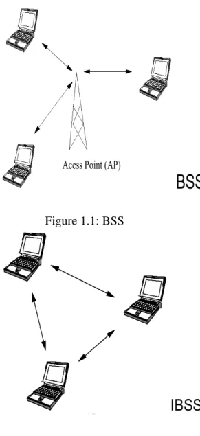
topologies for a single-hop network. The first one is the star topology (see Figure 1.1), where
the base station is in the center of the network and the other nodes are in the one-hop
neighborhood of the base station. In this topology all traffic flows through the base station. The
second topology is the fully connected single-hop topology (see Figure 1.2), where all the
Figure 1.1: BSS
Figure 1.2: IBSS
Ad hoc networks are wireless networks where all nodes cooperatively maintain
network connectivity. This type of network is well suited to fulfill the tactical communication
requirements of a small to medium size military group (i.e., a squad) or a law enforcement
group (i.e., police officers pursuing a criminal or airport security personnel searching a group
of passengers), where the members of the network may want to communicate simultaneously
Wireless hosts are often powered by batteries and battery life is not expected to increase significantly in the coming years. Therefore, power is arguably the scarcest resource for mobile
devices, and power saving has always been a major design issue for the developers of mobile
devices, wireless communication protocols and mobile computing systems. Since users
normally do not accept frequent recharging or changing of batteries, neither is it desirable for
users to carry a heavy battery pack, a lot of limitations are imposed on the operations of a
mobile device by power. To increase battery lifetime, it is important to design techniques for
reducing energy consumption by wireless hosts.
Previous researches have investigated energy conserving mechanisms at various layers
of the protocol stack, including work on Physical layer (Tuning transmission energy for higher
channel utilization. Power control [3][4][5] reduces the power level of a transmission
to achieve reduced power consumption while maintaining the transmission success rate and
network connectivity), medium access control (MAC) layer (power mode management)and
Network layer(Routing in an ad hoc network with energy-saving in mind). Since nodes in an
ad hoc network communicate via radio, and the radio channel is shared by all nodes, it
becomes necessary to control access to this shared media. Several authors have developed
channel access protocols to maximize throughput and minimize transmission delays. From
previous three solutions, we focus on MAC protocol to reduce the power consumption at each
node.
consumed by actual communication. This means that wireless network interfaces in the idle
state waste a significant amount of energy. Energy dissipation in the idle state cannot be
ignored because network interfaces often stay in the idle state for a long time. Thus to
conserve this energy, it is generally desirable to turn the radio off when they are not in use.
Much recent research proposed to reduce energy consumption in dense ad hoc networks by turning off devices that are not necessary for global connectivity. In addition, some MAC
protocols have also been proposed to conserve energy based on IEEE 802.11 PSM.
As noted above, in ad hoc networks, the wireless network interface
consumes energy except in the off state. In the awake state, the energy consumption in Lucent
IEEE 802.11 WaveLAN card [6] consumes 1 .65W, 1.4W and 1.15W in transmit, receive
and idle modes respectively. In the doze state, WaveLAN card consumes 0.045W. Clearly, the
energy consumed in the idle mode is almost the same with transmit mode. The idle power
consumption is significant, as hosts must maintain their network interfaces in idle mode in
order to cooperate in maintaining the ad hoc routing fabric. The hosts have to monitor the
channel and consume power even through the packets are not directed to them, thereby
unnecessarily consuming a large amount of energy.
1.1 Motivation
Having summarized the unique characteristics of Ad Hoc, we will focus on the Specific
Many applications require a peer-to-peer single hop infrastructure less reliable radio network
architecture that enables real-time communication. Voice and data communication is
commonly used in many Ad Hoc scenarios that include groups of people with no available
infrastructure support. Proposed protocol has been designed to be a very energy efficient,
reliable protocol to support real-time broadcasting.
1.2 The Challenges of Power Saving Mode in 802.11Ad Hoc
Networks
The relation among energy consumption, throughput and delays is a trade-off. Power
Saving Mode in ad hoc networks has some inefficient problem. First, Fixed ATIM window
size affects throughput and energy consumption. Secondly, serious contention and energy
consumption occur in ATIM and Data transmission window. Thirdly, when real-time
applications such as CBR Voice traffic are served, this scheme may cause intolerable delay
and possibly packet loss.
1.3 Thesis Objective and Organization
In the thesis, we focus on the power management in fully-connected ad hoc networks.
We assume that time is divided into beacon intervals which begin and end approximately at
the same time at all nodes. We propose a power saving efficient MAC protocol that
integrates voice and Data traffic with the QOS method and the ATIM window adjustment to
achieve a better trade-off between power consumption, network throughput and delay.
IEEE 802.11 PSM in DCF and related works. Chapter 3 presents our proposed protocol. In
Chapter 4, we describe our simulation model and discuss simulation results. Finally, a conclusion to this thesis is presented in Chapter 5.
Chapter 2
Overview of IEEE 802.11 Power Saving Mode and Related
Works
In this chapter, firstly, we will review the power management as defined in IEEE
802.11, and then discuss some drawbacks in the current standard in section 2.1. Much
research has been done in power saving for mobile devices in the past. We will also show the
inefficiency of the other power-saving mechanisms and will be presented in section 2.2.
2.1 Overview of IEEE 802.11 PSM
We briefly review the main operation of the power saving mode in an IEEE 802.11 ad
hoc network. According to the IEEE 802.11 power saving mode, all nodes are connected
synchronously by waking up periodically to listen beacon messages.This scheme requires the
synchronization among the stations. Therefore, a T S F ( time synchronization function) is
defined in the standard. To save energy, stations go to the Power Saving (PS) mode when no
incoming or outgoing traffic is present. In PS mode, the system is in a Doze state and its
transceiver is shut down to save power. If a node acquires the medium, it will send an
ATIM frame to the destination node based on the CSMA/CA access scheme. The ATIM
frame is announced inside the ATIM window. If the destination node receives the ATIM frame,
it will respond with an ATIM-ACK frame and stay active to receive data in the data
access scheme. If a node fails to send its ATIM frame in the current ATIM window, it should
retransmit the ATIM frame in the next ATIM window. If a node does not send or receive any
ATIM frame during the ATIM window, it will switch to PS mode to decrease power
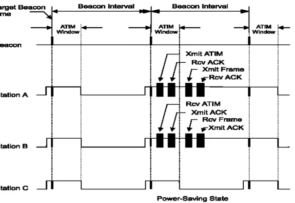
consumption until the next beacon interval begins. T he IEEE 802.11’s power management is shown in Figure 2.1-1.
Figure 2.1: Power-saving mechanism in IEEE 802.11
Fig 2.1-1 shows an example. Initially, all nodes wake up at the beginning of the beacon
interval. Since all nodes did not send or receive any ATIM frames in the ATIM window of
the first beacon interval, all nodes will switch to sleep state in the Data transmission window.
In the ATIM window of the next beacon interval, node A has a packet destined for node B.
transmit buffered data to node B based on the CSMA/CA access scheme.
The performance of PSM is affected by the size of the ATIM window.When the ATIM
window is too short with transmitting stations in the system, the contention in ATIM is high
and only a few stations can send their ATIMs successfully. Then the channel utilization of
data window of the same beacon interval is poor. If ATIM window is too long with
transmitting stations in the system, many stations can enter the data transmission. This will
cause not only higher contention in data window, but also the waste of energy for those who
couldn’t get a chance to transfer data during the current beacon interval, since all stations who
succeed in transferring their ATIMs are required to stay in Active Mode throughout the
beacon interval. Both the ATIM window and the beacon interval are fixed length. It was
shown in [7] that PSM performed well when the length of the ATIM window was
approximately 1/4 of the beacon interval. Furthermore, the IEEE 802.11 PSM has
two-contention transmissions (one for the ATIM frame and one for data packet). This will often
cause a mismatch of the number stations in each contention period. For example, we may
have many successful nodes in the ATIM window, but only a few nodes can transmit their
data packet in the data transmission interval due to the high contention in the data window.
The power-saving mechanism suffers several problems with end-to-end delays and
throughput. If a sender wants to immediately transmit packets to a receiver but has not
transmitted an ATIM frame to the receiver, the packets cannot be sent at once. Therefore,
Furthermore, if the network traffic is heavy, then a sender in PSM cannot inform a receiver of
its pending packets by the ATIM frames for an ATIM window, resulting in a declination of
throughput. Ad hoc networks in PSM have large end-to-end delays and a degraded throughput.
As will be seen from this thesis, we improve the energy efficiency in PSM without degrading
throughput.
2.2 Related Works
In the section, we review several existing power management protocols for IEEE
802.11ad hoc networks as following.
2.2.1 Power-Saving Mechanism in Emerging Standards for
Wireless LANs: The MAC Level Perspective
Woesner et al. [7] presented simulation results for the power saving mechanisms of two
wireless LAN standards, IEEE 802.11 and HIPERLAN. It showed the different sizes of beacon
intervals and ATIM windows in IEEE 802.11 had a significant impact on throughput and
energy consumption. The authors indicate that the ATIM window size should take
approximately 1/4 of the beacon interval. However, the effects of load variety is not put much
focus on. We can see here that it affects this optimal ratio between the ATIM window and the
beacon interval quite significantly.
2.2.2 A power-saving scheduling for IEEE 802.11 mobile ad hoc
networks
M. T Liu et al. [8] proposed an energy efficiency MAC protocol for IEEE 802.11
Interval dynamically to adapt to the traffic loads. All stations are required to be able to hear
from each other directly. Nodes that overhear ATIM frames will generate a contention-free
schedule for data transmission in the rest of the beacon interval, rather than let those nodes
that have succeeded to announce in the ATIM window to contend again for the data
transmission. With all the information received at each station during the ATIM window, a
deterministic scheduling can be generated. This not only eliminates extra contention in the
data transmission but also increases the efficiency of power saving.
2.2.3 An energy efficient MAC protocol for IEEE 802.11 WLANs
In [9], Wu et al. proposed an energy efficiency MAC protocol for IEEE 802.11 networks
by scheduling transmission after the ATIM window and adjusting the ATIM window
dynamically to adapt to the traffic Loads. But they did not consider the energy consumption
caused by overhearing among neighboring nodes. Nodes schedule those to-be-transmitted
data frames after ATIM window. According to a buffered data frame’s duration, nodes
determine the transmission order. Data transmission takes place to avoid unnecessary frame
collision and backoff time. Besides, nodes adjust the ATIM window dynamically to adapt to
Chapter 3
Power-Saving MAC Protocol
3.1 Overview
The proposed power-saving MAC is an energy-efficient dynamically-adjustable
ATIM window protocol designed for real- and non-real time data broadcasting. Under
the proposed protocol, data is transmitted according to a dynamically updated
transmission schedule. Each node utilizes prioritized contention based on Enhanced
Distributed Channel Access (EDCA) for periodical real-time (CBR Voice) and non-real
time (Data) traffic. Each node with real-time (CBR Voice) traffic initializes access to
medium is through contention, but once a node reserves transmission time, its
reservation time in the subsequent Beacon Interval continues automatically as long as
the node continues to broadcast a packet in each Beacon Interval. Thus, nodes need only
contend for transmission time at the beginning of Real-time (CBR Voice) traffic bursts in
the ATIM window.
Nodes transmitting Real-time (CBR Voice) traffic also require the Reservation
Occupation Table maintenance scheme to ensure correct channel utilization. The CBR
Voice nodes transmit Beacon messages which carry the Reservation Occupation Table
to each network node at the beginning of the ATIM window. Beacon generator
Figure 2.1 indicates that the fixed lengths of the ATIM window and the beacon
interval of IEEE 802.11 ad hoc power saving mode (PSM) often consume excess energy.
The inefficiency of the fixed ATIM window size under different traffic loads requires
dynamic adjustment of the ATIM window size.
Finally, in the power saving mode (PSM) of IEEE 802.11, nodes that successfully
announce ATIM frames stay active during the entire beacon interval. After Data
transmission, nodes need not remain active state. After a node finishes Data
transmission, the proposed power-saving MAC protocol switches the node from an
active state to a sleep state to minimize power consumption. The novel feature of the
proposed MAC protocol is the decreased idle time in active state and the switchover
times (active-to-sleep state or sleep-to-active state).
The following sub-sections describe these features in more detail.
3.2 Basic Operation
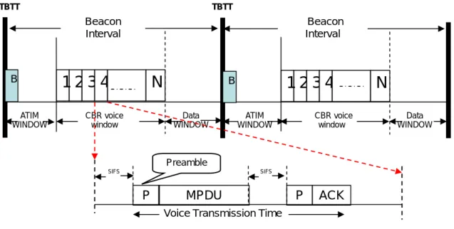
The proposed power-saving MAC protocol matches time-frame duration to
the periodic rate of voice packets. Figure 3.1 presents the frame format. Each frame
consists of two sub-frames: a ATIM sub-frame and a data transmission sub-frame. The
ATIM sub-frame consists of a beacon generation window and a ATIM window. The data
transmission sub-frame consists of a CBR Voice window and Data
Figure 3.1: Representation of Proposed power-saving MAC frame format
3.2.1 Definition for new management frames in ATIM
window
Because the ATIM and ATIM_ACK frame defined in the standard has MAC header,
Frame Check Sequence (FCS) and an empty frame body, the standard was slightly
modified to include that information in the ATIM and ATIM_ACK frame. A frame body
of several octets was added to deliver that information can be easily done and will not
affect other operations defined in the standard. Besides, the beacon frame carries the
ROC (Reserved OCcupation Table) to indicate Reserved CBR Voice information. The
following definitions and frame formats are used in the proposed protocol.
ROC (Reserved OCcupation Table)
– Indicates Reserved CBR Voice information including Source address, Destination address, and Transmission Order
– Beacon Frame carries ROC used by residential nodes
Data WINDOW ATIM WINDOW CBR voice window Data WINDOW CBR voice window ATIM WINDOW
1 2 3 4
N
Beacon Interval B1 2 3 4
N
Beacon Interval B TBTT TBTT MPDU PVoice Transmission Time
SIFS SIFS
P ACK
BGS (Beacon Generation Sequence)
– Nodes with reserved CBR Voice must send Beacon with ROC at TBTT in sequence
– The beacon transmission sequence with ROC
• Every CBR Voice responder attached to Every CBR Voice sender to form the BGS.
Figure 3.2: Beacon Frame with ROC
Figure 3.3: ATIM and ATIM_ACK Frame for Data
Time Stamp IBSS Parameter Set Capability Information Beacon
Interval SID ~ ROC
4B 2 Frame Control Duration DA SA Seq -ctl MAC Header BSSID FCS 2B 2B 6B 6B 6B 2B 4B Payload ATIM Frame Frame Contro Release ROC
/ Reserve ROC TX pair No DATA Length
1b 3b 4b 2 Duration DA SA -ctl Seq MAC Header BSSID FCS 2B B 6B 6B 2B 4B 6B Payload 000 for Data Don’t care 001~110 for CBR Voice 0/1 ATIM_ACK Frame For Data 2 Frame
Control Duration DA BSSID -ctl Seq FCS
2B B 6B 6B 2B DATA 4B
Length MAC Header
3.2.2 Beacon generation procedure
In the initial startup stage, nodes at TBTT that have no BGS within the Ad Hoc
contend to transmit the beacon frame (Fig. 3.4). Each node calculates a random delay
uniformly distributed within the range from 1/4 to 2*CWmin*SlotTime (CWmin is the
minimum contention window used in the backoff mechanism), then waits for the
duration of the delay using the backoff mechanism. When the delay counter expires, the
beacon is transmitted with a timestamp, which is a copy of the sender’s local TSF timer
of the sender, with some adjustment. Nodes cancel the beacon transmission if a beacon
arrives before their random delay counter expires. When a beacon is successfully
received, stations set the TSF timer according to the timestamp of the beacon if the value
of the timestamp is later than the TSF timer of the station itself in PSM of 802.11.
Therefore, the TSF timer can only be adjusted forward. In the proposed protocol, Timers
can be set both forward and backward to ensure that all nodes wake up simultaneously.
Figure 3.4: Beacon generation Window
As soon as nodes have BGS, those that have reserved bidirectional CBR Voice must
TBTT
1/4*CWmin*SlotTime 2*CWmin*SlotTime
B
B
B
Beacon without ROC
send a Beacon with ROC at TBTT in turn. If the Beacon generator node fails, the
remaining network nodes should be able to compensate for this situation and should be
able to continue normal operation as quickly as possible.The BGS is a more natural and
complete way of backing up the beacon generator and it provides a perfect beacon
transmission order list of ROC after ATIM exchange. Every CBR Voice responder is
attached to CBR Voice sender to form the BGS. Nodes that have reserved CBR Voice
can listen for the beacon and become the beacon generator whenever the previous beacon
generator fails. The first sender in the sequence is the first generator; the second sender is
the second generator; and the senders append the responders. The backup nodes listen to
the beacon, which is a part of normal network operation. If the second generator does not
hear the beacon for a short interframe space (SIFS) time, then the first generator is
assumed dead and the second generator modifies the ROC and transmits the beacon with
ROC. If the beacon is not transmitted for two SIFS times, then the third generator
understands that both generators are dead. It then modifies ROC and transmits the
beacon. If after N SIFS times no beacon is transmitted, then the rest of the nodes
understand that No CBR Voice is reserved, and each node calculates a random delay
uniformly distributed within the range between 1/4 and 2*CWmin*SlotTime and the
transmitted beacon. The Maintenance scheme of Reserved OCcupation Table can be
summarized as follows:
Beacon Generation Sequence (Fig. 3.5).
• If reservation is successful, pair nodes continues to reserve the Transmission in future cycles (Fig. 3.6).
• Finally, nodes send ATIM message and release the piggyback ROC after the conversation is completed or if the partner dies (Fig. 3.7).
• If the pair Nodes suddenly shut down, the other nodes should know the pair nodes have died and modifies ROC.
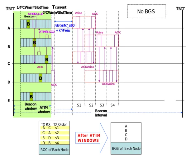
20 TBTT Beacon Interval Beacon window ACK ATIM(B,D,1) ACK CW win AIFS(AC_BK) + 2*CWmin*SlotTime 1/4*CWmin*SlotTime Beacon B B B B B ATIM window ATIM(A,C,1) B A C D E TBTT After ATIM WINDOWS Voice ACK S1 S2 S3 ACK Voice ACK Voice Voice ACK S4 TX RX TX Order
ROC of Each Node
A B C D BGS of Each Node A C s1 C A s2 B D s3 D B s4 No BGS Tcurrent
21
TBTT
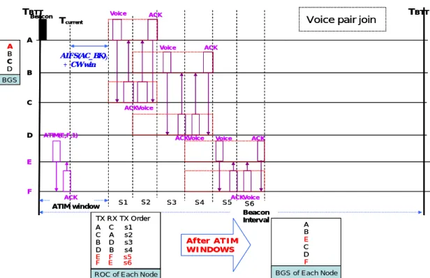
ROC of Each Node A B C D BGS A B E C D F BGS of Each Node Beacon Interval ATIM window B A C D E S1 S2 S3 S4 S5 Voice ACK ACK Voice ACK Voice Voice ACK Voice ACKVoice ACK S6 Beacon Tcurrent TBTT F ATIM(E,F,1) ACK CW win ) AIFS(AC_BK) + After ATIM WINDOWS TX RX TX Order E F s5 F E s6 A C s1 C A s2 B D s3 D B s4
Voice pair join TBTT
ROC of Each Node A B C D BGS A B E C D F BGS of Each Node Beacon Interval ATIM window B A C D E S1 S2 S3 S4 S5 Voice ACK ACK Voice ACK Voice Voice ACK Voice ACKVoice ACK S6 Beacon Tcurrent TBTT F ATIM(E,F,1) ACK CW win ) AIFS(AC_BK) After ATIM WINDOWS TX RX TX Order E F s5 F E s6 A C s1 C A s2 B D s3 D B s4
Voice pair join
Figure 3.6: Maintenance scheme of Reserved OCcupation Table (二)
22
As long as Receiving ATIM Piggyback Release, each node Modify ROC
ROC of Each Node TX RX TX Order B D s3 D B s4 E F s5 F E s6
ROC of Each Node TX RX TX Order Beacon Interval TBTT ATIM window B A C D E Beacon Tcurrent TBTT F ATIM(A,C,0) AIFS(AC_BK) CW win + S1 S2 S3 S4 ACK Voice Voice ACK Voice ACKVoice ACK B E D F BGS of Each Node A B E C D F BGS B D s1 D B s2 E F s3 F E s4 After ATIM WINDOWS A C s1 C A s2 ACK
Voice pair leave
3.2.3 ATIM Information Exchange procedure
After the beacon transmission window, nodes enter the ATIM window. For ATIM
information exchange, the system piggybacks the number of pending packets of ATIM
announcement for Data. The information about the sender, receiver, and length of the
pending data are contained in ATIM frame denoted ATIM (Sender ID, Receiver ID, Data
Length). The transmission Release/Reservation status of ATIM announcement for CBR
Voice is also piggybacked. The information about the sender, receiver, and
Release/Reservation status of the CBR Voice traffic is contained in the ATIM frame
denoted as ATIM (Sender ID, Receiver ID, TX status). According to IEEE 802.11
regulations, all nodes are fully connected and all PS mode nodes can wake up at almost
the same TBTT. At the TBTT, each node wakes up for an ATIM window interval. If a
node with buffering Data to a PS mode node, it sends an ATIM frame to the PS mode
node within the ATIM window period. Upon receiving the ATIM frame, the PS mode
node responds to an ATIM ACK to the sender of the ATIM frame and completes the
reservation of the data frame transmissions. If a node with buffering CBR Voice to a PS
mode node, it sends an ATIM frame to the PS mode node within the ATIM window
period. Upon receiving the ATIM frame, the PS mode node responds with an ATIM
ACK to the sender of the ATIM frame and joins the Reservation OCcupation Table
or if their pair nodes do not respond to with an ATIM ACK to the sender during CBR
voice transmission. Due to the broadcast nature of the wireless medium, each node can
overhear the ATIM exchange information and get all node transmission tables (Data
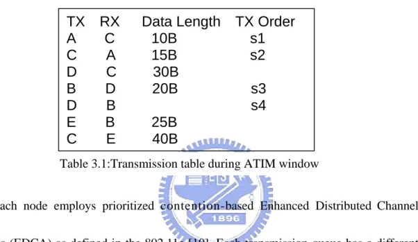
Length and CBR Voice Transmission Order) as Table 3.1 shows.
Each node employs prioritized contention-based Enhanced Distributed Channel
Access (EDCA) as defined in the 802.11e [10]. Each transmission queue has a different
interframe space (AIFS) and a different contention window limit. Each node that
intends to transmit data calculates its priority according to the collected data profiles. The
proposed protocol uses Data and voice traffic only. Nodes adjust the contention window
size and AIFS time. T he smaller i t s AIFS, the higher t he priority a node can have.
Similar protocols apply to the contention window size. Figure 3.8 illustrates the time
diagram of EDCA [10]. The 802.11e suggests the use of different AIFS and different
contention window limits according to different ACs. Table 3 . 2 shows the parameters
for the maximum contention window (CWmax), the minimum contention window(CWmin)
TX RX Data Length TX Order
A C 10B s1
C A 15B s2
D C 30B
B D 20B s3
D B
10B
s4
E B 25B
C E 40B
and AIFS for each AC.
Figure 3.8: The timing diagram of 802.11e EDCA[10]
AC CWmin CWmax A
I
AC_BK aCWmin aCWmax 7
AC_BE aCWmin aCWmax 3
AC_VI (aCW
min + 1)/2 aCWmin 2
AC_VO (aCW
min + 1)/2 (aCWmin + 1)/2 2
Table 3.2: The default EDCA parameters [10]
The value of AIFS is determined by the following equation (1)[10]:
AIFS = AIFSN × aSlotTime + SIFS (1)
where the value of AIFS Number (AIFSN) is an integer greater than zero and is dependent
3.2.4 Traffic-Load oriented ATIM window adjustment
To conserve the power used by PS mode nodes and to improve network throughput,
the relationship between the lengths of the ATIM window and the corresponding beacon
interval is discussed in [7] as mentioned above. The authors indicated that the ATIM window
size should take approximately 1/4 of the beacon interval. The proposed scheme can
dynamically adjust the ATIM window according to the channel idle time and the actual
traffic load of the network. Each node senses how long the channel is continuously idle
during the ATIM window. If nodes sense that the channel is idle longer than AIFS
(AC_BK) + CWmin, the assumption is that no nodes have buffered frames to send.
Besides, if ATIM collision occurs and Remaining Beacon Interval ≧ TMAXMPDU,
nodes could stay awake until no further ATIM collision occurs or remaining Beacon
Interval ≦ TMAXMPDU.Therefore, all nodes can close the ATIM window and enter the
data transmission window according to transmission table. The following Fig. 3.9 is the
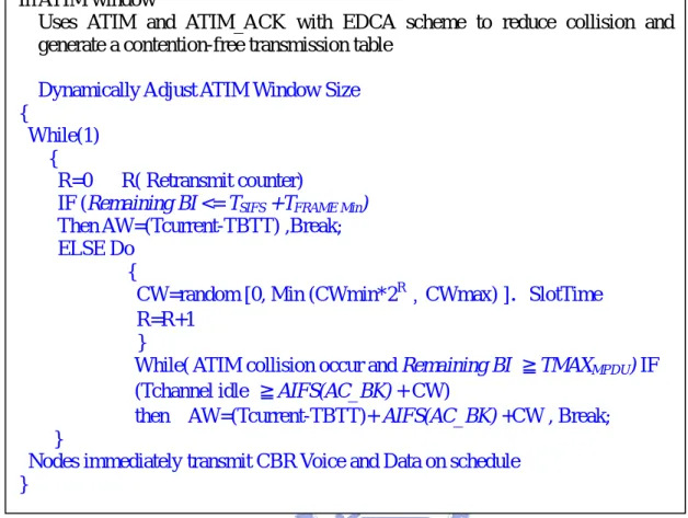
Figure 3.9: Traffic-Load oriented ATIM window adjustment In ATIM window
Uses ATIM and ATIM_ACK with EDCA scheme to reduce collision and generate a contention-free transmission table
Dynamically Adjust ATIM Window Size {
While(1) {
R=0 R( Retransmit counter)
IF (Remaining BI <= TSIFS +TFRAME Min)
Then AW=(Tcurrent-TBTT) ,Break; ELSE Do
{
CW=random [0, Min (CWmin*2R﹐CWmax) ].SlotTime R=R+1
}
While( ATIM collision occur and Remaining BI ≧TMAXMPDU) IF
(Tchannel idle ≧AIFS(AC_BK) + CW)
then AW=(Tcurrent-TBTT)+ AIFS(AC_BK) +CW , Break; }
Nodes immediately transmit CBR Voice and Data on schedule }
3.2.5 Transmission Window operation
At the end of ATIM window, each PS mode node that successfully have finished
ATIM exchange during an ATIM window wakes up to transmit its Voice/data packets
and then enters a doze state according to its individual transmission order. Each node
transmits CBR Voice according to the ROC and transmits data according to the Data
transmission scheme.
To minimize the switchover penalty of data transmission, the heuristic algorithm
developed by Prof .Tsern-Huei Lee et al. is used. The sub-optimum heuristic algorithm
that minimizes the number of switchovers from the Doze state to the Awake state is
determined based on graph theory. Details of the heuristic algorithm are shown below.
Heuristic Algorithm
Step 1. Set Schedule_List = ∅.
Step 2. Select a node n of graph G with minimum degree.
Step 3. Assume that Neighbor(n) = {n1, n2, …, n } and deg(j n )i ≤ deg(ni−1) for all i,
2≤ i ≤ j. Append the list of edges (n, n1), (n, n2), …, (n, n ) to Schedule_List j
and then remove these edges from graph G.
Step 4. Remove a node if all edges incident on it are removed.
Step 5. Let G denote the resulting graph. Stop the algorithm if graph G becomes empty. Step 6. While node n is removed, set n = j nj−1 till n = n1.
The scenario in Fig 3.10 below is an example of bidirectional CBR Voice and data transmission operation. Beacon Interval ATIM window TBTT Voice ACK S1 S2 S3 ACK Voice ACK Voice DATA DATA DATA DATA DATA DATA Voice ACK S4 B A C D E ATIM(A,C,1) ACK ATIM ATIM(B,D,1) ATIM ATIM ACK ATIM ACK ACK ACK BeaconACK ATIM ACK ACK TBTT
Figure 3.10: Example of our proposed protocol omitted the beacon generation procedure procedure
To simply the presentation, the beacon generation procedure in the previous section is
omitted. Five PS mode nodes involved in the ATIM frame transmission are the following:
A,B,C,D and E. During the ATIM window, ATIM frames are announced successfully as
follows, i.e., ATIM(A, C, 1),ATIM(B, D, 1), ATIM(A, C, 10), ACK(C,A, 15) ,ATIM(D,
C, 30),ATIM(B, D, 20), ATIM(E, B, 25),ATIM(C, E, 40). Therefore, at the end of the
ATIM window, all network nodes should maintain the transmission table in Tables 3.3
and 3.4 if no transmission errors
occur.
Table 3.3: Example of bidirectional CBR Voice Table After ATIM Windows TX RX TX Order A C s1 C A s2 B D s3 D B s4 Voice ROC TX RX Data Length TX Order
A C 10B s1 C A 15B s2 D C 30B B D 20B s3 D B AA s4 E B 25B C E 40B Transmission Table
Transmission Table TX RX Data Length A C 10B C A 15B D C 30B B D 20B E B 25B C E 40B Graph presentation A C D B E Node Degree A 1 C 3 D 2 B 2 E 2 Heuristic algorithm TX RX A C C A C D C E E B B D TX RX Data Length A C 10B C A 15B C D 30B C E 40B E B 25B B D 20B Transmission Order in Data window Schedule_list
Table 3.4: Example of Data Transmission Table
After the ATIM window, firstly, nodes with bidirectional CBR Voice transmit voice
packet according to ROC. The A and C wait a SIFS time, and A transmits a Voice packet
according to ROC and C response ACK frame to A. At the same time, B and D wake up
according to ROC. After a SIFS time, C transmits a Voice packet to A according to ROC.
The A then sends a response to ACK frame to C. After completing the exchange of
bidirectional CBR Voice traffic, A and C go into a doze state. Then B continues to
transmit bidirectional CBR Voice to D according to ROC. The D follows the same rule as
A and C. After completing the bidirectional CBR Voice transmission, the nodes transmit
data based on Data transmission order. At the same time, A and C wake up at the CBR
Voice transmission time of D to B and A transmit data frames to C follows the Data
transmission order. Other nodes then follow the same rule as A and C. Finally, B and D
transmit their data frames. After completing the Data transmission, B and D enter a doze
state until the end of the beacon interval since there is no entry in their transmission table.
This chapter proposes a new protocol for improving throughput and power saving by
dynamically adjusting ATIM window length. Nodes are also allowed to stay awake for
only a fraction of the beacon interval following the ATIM window. Consequently, more
stations can go into sleep mode in the middle of the beacon interval and stay in the sleep
mode for a longer duration. Chapter 4 presents the results obtained by simulating the
PSM scheme in IEEE 802.11, the proposed protocol, and power-saving mechanism
proposed by the M. T Liu et al. [8] and the energy efficiency MAC protocol proposed by
Chapter 4
Simulation and Discussion
This chapter describes computer simulations to evaluate the energy conservation
performance of the proposed protocol in the last section for an ad hoc wireless LAN
consisting of ten to twenty hosts. The assumptions are that all hosts are fully-connected,
and no transmission errors have occurred, implying that no packet is lost due to poor
quality of the channel, and all protocol can avoid overhearing in data transmission
window.
4.1 Simulation Model
For our simulation, C++ i s u s e d to implement a simulator The proposed MAC
protocol is compared with the original IEEE 802.11 power-saving operation and the M.
T Liu et al. [8] proposed power-saving mechanism, and the Wu et al. [9] proposed
energy efficiency MAC protocol. Two traffic types are modeled.
– Only Pure Data
– Pure Data and CBR Voice (6pairs in 10 nodes)
Each simulation was performed 100 times. A 2Mbps channel rate is assumed. To
investigate non-real time and real-time traffic over an ad hoc network, two traffic types
are considered.
z Pure Data traffic: The arrival rate of data frames from each station is smaller than 10 kbits within 0.1sec. The frame size is 256 bits to 1024 bits long.
z Voice traffic: Voice traffic is usually considered constant bit rate (CBR) traffic. After referring to other voice traffic models [11] , the data rate of voice traffic is set
to 64Kbps. The value of maximum tolerance is 20 ms. Voice traffic is assumed to
have highest priority, and pure data traffic has the lowest priority. Voice belongs to
real-time traffic and has the maximum tolerance delay time. According to the traffic
models defined above, Table 4.1 summarizes the traffic parameters of the protocol.
Table 4.1: Simulation Parameters
AIFSN=7,CWmin=15 AC_BK
AC_VO
2Mbps Channel bit rate
64Kbps Voice coding rate
20us Slot time
5ms
0~1240us Beacon window size
800us Doze-to-awake time 10us SIFS 50 us DIFS 20ms Beacon Period (Voice Delay Bound )
ATIM window size
1024 Maximum Contention window
31 Minimum Contention window
Value
Parameters
AIFSN=2,CWmin=3 128bits PHY Header 272bits MAC Header 22Bytes ATIM ACK 28Bytes ATIM Frame 256,512,768,1024bits Data FrameValue
Packet Length
0.045W Doze 1.65W Transmitting 1.4W Receiving 1.15W IdleEnergy
mode
4.2 Performance Measurements
From many papers analysis on energy saving issues, some conditions are required
be covered for each performance measurement:
1. Energy goodput: We used this energy goodput define in [12] to evaluate power
efficiency. Eergy goodput = yConsumed TotalEnerg ransmitted TotalBitsT
The unit of energy goodput is bits/Joule, this metric measures the amount of data
delivered per joule of energy. The higher the energy goodput is, the lower the
energy it consumes.
2. Throughput: The throughput is defined the channel rates that can be used to transmit
pure frame by all traffics types of stations. The contention cost is excluded from the
throughput. Throughput = TotalTime lPackets fSuccessfu theAmounto * th Frame_Leng
3. Average Frame Delay: A period of the time from a frame arrives the system to it
4.3 Simulation Results
Figures 4.1 and 4.2 show the Energy goodput (bits/joule) for pure data and voice &
pure data traffic, respectively. Figure 4.1 shows the Energy goodput for four
power-saving protocols with data traffic. When the number of nodes increases, the proposed
protocol always achieves better energy goodput than any other protocol because it
minimizes switchover time in data transmission window. The protocol consumes less
power than other protocols do.
Figure 4.2 illustrates the Energy goodput for power saving protocols with voice &
pure data traffic. When the number of voice pairs increases, a node spends less time in
doze state because of voice transmission. Because the proposed protocol provides a
Figure 4.1: Number of Nodes v.s Energy goodput with pure data traffic
Figure. 4.2: Number of Voice pair v.s Energy goodput with pure data &Voice traffic
E n e r g y g o o d p u t
6 0 0 0 8 0 0 0 1 0 0 0 0 1 2 0 0 0 1 4 0 0 0 1 6 0 0 0 1 8 0 0 0 2 0 0 0 0 2 2 0 0 0 2 4 0 0 0 2 6 0 0 0 2 8 0 0 0 1 0 1 2 1 4 1 6 1 8 2 0 N u m b e r o f N o d e sbits per joule
P S M L iu W u p ro p o s e d
Energy goodput
5 0 0 0 1 5 0 0 0 2 5 0 0 0 3 5 0 0 0 4 5 0 0 0 5 5 0 0 0 6 5 0 0 0 7 5 0 0 0 8 5 0 0 0 9 5 0 0 0 1 0 5 0 0 0 1 1 5 0 0 0 1 2 5 0 0 0 1 3 5 0 0 01
2
3
4
5
6
N um ber of V oice pair
bits per joule
PSM Liu W u p ro p o sed
Figures 4.3 and 4.4 illustrate the average throughput (bits/sec/node) for pure data
and voice & pure data traffic, respectively. Figure 4.3 shows the average throughput for
four power saving protocols with data traffic. In the simulation results, PSM with ATIM
window size of 5 ms may suffer severe throughput degradation . If the ATIM is too
small in PSM, time is inadequate to announce ATIM. The Wu protocol and the
proposed protocol can achieve higher throughput by choosing a suitable ATIM window
with traffic load. Liu also used variable beacon interval to accommodate data
announced in ATIM window.
Figure 4.4 illustrates the average throughput for four power saving protocols with
voice & pure data traffic. When the number of voice pair increases, the proposed
protocol has fine average throughput because it spends less time on contention. Voice
traffic can again be reserved to reduce contention among the nodes in ATIM window.
The other protocols have no such reserved scheme to avoid contention in ATIM
window.
Figure 4.3: Number of Nodes v.s Average throughput with pure data traffic
Figure 4.4: Number of Voice pair v.s Average throughput with pure data &Voice traffic
A verage throughput
9500
9600
9700
9800
9900
10000
10
12
14
16
18
20
N um ber of N odes
bits per sec per node
PSM Liu W u p ro p o sed
A verage throughput
0 10000 20000 30000 40000 50000 60000 70000 80000 900001
2
3
4
5
6
N um ber of V oice pair
bit
s per sec per node
PSM Liu W u p ro p o se d
Figures 4.5 and 4.6 illustrate the average delay (msec per packet) for pure data and
voice & pure data traffic, respectively. Figure 4.5 shows the average delay for four
power saving protocols with data traffic. According to this figure, the PSM reveals a
large average delay because it does not have sufficient time to announce the ATIM
frame in the current ATIM window and contention in data transmission window. Nodes must
retransmit ATIM frames in the next ATIM window, incurring a long average delay.
Figure 4.6 illustrates the average delay for four power saving protocols with voice
& pure data traffic. When the number of voice pairs increases, the protocol has better
average delay because real time frames have the higher priority than pure data frame
and has a reserved scheme to transmit continuously. The other protocols have no such
Figure 4.5: Number of Nodes v.s Average Delay with pure data traffic
Figure 4.6: Number of Voice pair v.s Average Delay with pure data &Voice traffic
Average delay
0
200
400
600
800
1000
10
12
14
16
18
20
N um ber of N odes
msec per packet
PSM Liu W u p ro p o sed
A v e ra g e d e la y
0 1 00 2 00 3 00 4 00 5 00 1 2 3 4 5 6N u m b er o f V o ice p air
msec per packet
PSM L iu W u p ro p o se d
Chapter 5
Conclusion
This thesis presents an energy-efficient MAC protocol to support voice/Data traffics
over ad hoc networks. The simulation results also demonstrate that the protocol performs
much better than the other protocols with real-time and non-real time traffic.
Data transmission is assumed to be perfect and fully connected. Future studies should
Bibliography
[1] IEEE Std 802.11b, IEEE Standard for Wireless LAN Medium Access Control
(MAC) and Physical Layer Specifications: Higher-Speed Physical Extension in the 5GHz Band, 1999.
[2] IEEE Std 802.11a, IEEE Standard for Wireless LAN Medium Access Control (MAC) and Physical Layer Specifications: Higher-Speed Physical Extension in the 2.4 GHz Band, 1999.
[3] J. Gomez, A. T. Campbellm, M. Naghshineh, and C. Bisdikian, 2001, “Conserving transmission power in wireless ad hoc networks,” in Proc. Of IEEE International
Conference on Network Protocols.
[4] Shih Liu Wu, Yu Chee Tseng Jang Ping Sheu “Intelligent medium access for Mobile ad hoc networks with busy tones and power control,” IEEE journal on
Selected Areas in Communications, pp. 1647-1657, Sep. 2001.
[5] E. S. Jung and N. H. Vaidya, “Mediun access control for ad hoc Networks: a Power control MAC protocol for ad hoc networks,” in Proc. ACM MOBICOM, Sep. 2002, pp. 26-46.
[6] Feeney L.M., and Nilsson M., “Investigating the Energy Consumption of a
Wireless Network Interface in an Ad Hoc Networking Environment”, INFOCOM 2001.
[7] Hagen Woesner, Jean-PierreEbert, MortenSchlager, andAdam Wolisz, ”Power-saving mechanisms in emerging standards for wireless lans : The mac level perspective”, IEEE Personal Communications 1998
[8] Ming Liu, and M.T. Liu, ” A Power-saving Scheduling for IEEE 802.11 Mobile
Ad Hoc Network”, ICCNMC 2003. 2003 International Conference on, 20-23 Oct. 2003 Pages:238 – 245
[9]Wu, S.L., Tseng, P.C.: An energy efficient mac protocol for IEEE 802.11 WLANS. In CNSR 2004. (2004) 137–145
Quality of Service (QoS), D4.4, Jun. 2003
[11] S.-T. Sheu and T.-F. Sheu, DBASE: A Distributed Bandwidth Allocation/ Sharing/Extension Protocol for Multimedia over IEEE 802.11 Ad Hoc Wireless LAN," in Proc. of the IEEE INFOCOM'01., vol. 3, pp. 1558{1567,2001.
[12] Takeuchi S., Yamazaki K., Sezaki K., and Yasuda Y., ”An improved power saving mechanism for MAC protocol in ad hoc networks” , GLOBECOM '04. IEEE
![Table 3.2: The default EDCA parameters [10] The value of AIFS is determined by the following equation (1)[10]:](https://thumb-ap.123doks.com/thumbv2/9libinfo/8382569.178265/30.892.94.728.222.843/table-default-edca-parameters-value-determined-following-equation.webp)