IEEE JOURNAL OF QUANTUM ELECTRONICS, VOL 25, NO 2, FEBRUARY 1989 139
Quantum Electronics Letters
Operation
of
an All-Optical Bistable Device Dependent upon Incident and
Transmitted Optical Power
RALPH S. JAMESON A N D WEN-TSERN LEEAbstract-In this letter we describe and demonstrate the optically bistable operation of a n all-optical nonlinear Fabry-Perot etalon (NLFP) in which the power-dependent cavity phase shift has a contri- bution dependent upon the internal cavity power and a contribution directly dependent upon the power incident on the cavity. When the contributions have the same parity, the optically-bistable behavior is essentially the same as that seen in the now standard bistable NLFP (counterclockwise hysteresis in transmission). For opposite parity there is a range of relative strengths for which bistable operation cannot be obtained, but outside of that range bistable behavior having clockwise hysteresis in transmission is possible. We present a demonstration of this latter bistable behavior in which the NLFP was a GaAlAs laser diode amplifier driven by a similar diode laser. Low-frequency mod- ulation of the laser power by direct variation of the laser drive current produced a small shift in laser wavelength proportional to the laser power, providing the cavity phase shift term proportional to the inci- dent power, while the nonlinear refractive index of the NLFP provided the phase shift proportional to the transmitted power.
I. INTRODUCTION
N THE conventional operation of a nonlinear Fabry-
I
Perot etalon (NLFP) nonlinearity and hysteresis may be observed in the transmitted power due to a cavity phase shift dependent upon the optical power within the etalon. Since the transmitted power is proportional to the internal power, and since it can be measured directly, a conven- tional NLFP can be considered to operate with a cavity phase shift dependent upon transmitted power. By con- trast, a hybrid electrooptical bistable device may use a combination of incident, reflected, or transmitted optical power to control the cavity phase shift electronically. With this dependence, the behavior can be substantially differ- ent from a conventional all-optical NLFP. Smith, Turner, and Mumford [ 13 demonstrated a hybrid Fabry-Perot with an internal electrooptic crystal inducing a phase shift pro- Manuscript received February 18, 1988; revised September 6, 1988. This work was supported by the National Science Council of the Republic of China under Grant NSC76-0608-E009-05.R. S. Jameson was with the Institute of Electro-Optical Engineering, National Chiao Tung University, Hsinchu 300, Taiwan, Republic of China. He is now with the Solid State Technology Center, AT&T Bell Laborato- ries, Brieningsville, PA 18031.
W.-T. Lee was with the Institute of Electro-Optical Engineering, Na- tional Chiao Tung University, Hsinchu 300, Taiwan, Republic of China. He is now with the Department of Laser Technology, Mechanical Industry Research Laboratories, Industrial Technology Research Institute, Chu- tung, Hsinchu, Taiwan 31015, Republic of China.
IEEE Log Number 8825437.
portional to the light reflected from the cavity, and ob- served bistability in the transmitted power having a clock- wise hysteresis loop, opposite in sense from conventional hysteresis. Cavityless devices based on electrooptic po- larization rotation [2]-[4] proportional to both incident and transmitted power have shown similar clockwise transmission bistability . Gibbs [5] noted that an all-opti- cal analog of these hybrid devices could be built by in- jecting part of the input signal through the edge of the etalon to make a nonresonant contribution to the cavity phase [6]. A device employing such edge-injection has been built, but was operated in a slightly different manner In this letter we generalize the description of an NLFP dependent upon incident power Pin and transmitted power
Pout, writing the etalon single pass cavity phase shift as [71.
where cpo is the initial cavity detuning, and
0
andr
are appropriate nonlinear phase shift coefficients. (Behavior dependent upon reflected power may be written in terms of Pin and Pout.) Section I1 presents the basic analytic treatment and discusses the differences in performance be- tween conventional and two-term devices, and differences between two-term devices having terms with the same and opposite parity. In Section I11 we report on the all-optical operation of an NLFP having cavity phase shift dependent upon both transmitted and incident power. At low speed (several Hz) this device is well described by the basic two-term theory, and at higher speeds illustrates the effect of varying0
and I’ during operation.11. THEORETICAL ANALYSIS
Previous work with mirrorless [2] and Fabry-Perot [ 13
electrooptic devices has presented analyses relevant to the two-term NLFP operation we describe. The present anal- ysis is more general and extended. We can write the NLFP transmission both as an Airy function of cp
140 IEEE and [with (l)] as a linear function
using etalon front and rear reflectivities Rf and Rb, thick- ness D , linear refractive index n, operating wavelength h, single pass absorption (or gain) coefficient a D effective
mean reflectivity R, = exp ( - a D )
*
a,
peaktransmission A = ( 1 - R f ) ( 1 - R b ) / ( 1 - R , ) 2 , and coefficient of finesse F = 4 R a / ( 1 - R a ) 2 . The method of graphical solution of (2) and (3) to find Pout versus Pin
is well known for the case of @ = 0 [8]: TL ( ( 0 ) produces
a family of lines with different Pin that intersect at the
point ( c p = cpo, T = 0), whicl we denote as the pivdt point. For @/I'
>
0 this pivot point moves onto the neg- ative Taxis, as shown in Fig. l(a). Fig. l(b) illustrates the type of nonlinear transmission and hysteresis pro- duced in this case, which is qualitatively similar to con- ventional NLFP behavior, although the hysteresis loop is generally narrower than that for conventional operation of the same cavity. With (1)-(3) strictly valid and with suf- ficient input power, counterclockwise transmission bista- bility can be obtained whenever -@/I'<
A / ( 1+
F), which is the minimum transmission level. For -@/I'>
A the pivot point lies above the Airy curve in Fig. l(c), with the intersections of TL and TA lying in the second quadrant, producing the nonlinear transmission shown in Fig. l(d). With increasing incident power the transmis- sion first tunes through a maximum, and then switches to a low state. The result is a clockwise hysteresis in the transmitted power. In the range A / ( 1
+
F ) I -@/I' I A the specific values of F, cp - cpo, and @/I' must be examined to determine whether TL can have multiple in- tersections with TA, and, if there are multiple intersec- tions, whether hysteresis is clockwise, counterclockwise, or is not attainable by intensity variation. For the balance of the letter we will deal with the case of clockwise trans- mission hysteresis.We can conceive of two general schemes in which an all-optical NLFP has phase dependence upon both trans- mitted and incident power. In the first the @Pin contribu- tion is due to a slight variation in operating wavelength proportional to Pin, such as that seen when the drive cur- rent of a diode laser is varied. In typical diode laser op- eration the laser output power PL varies as PL = C ( iL -
i t h ) for laser pump current iL, threshold current i t h , pro-
portionality coefficient C, and iL
>
ith. For slow varia- tions, the laser wavelength h changes linearly with iL [9]-[ 111 due to thermal variation of the bandgap. For slow iL
variation we may obtain a @Pin contribution from a con- ventional NLFP by writing the etalon phase as
For small variations in h the first term on the right can be expanded to yield
JOURNAL OF QUANTUM ELECTRONICS, VOL. 25, NO. 2, FEBRUARY 1989
Fig. 1 . Illustration of bistable operation in transmission for
f i / r
> 0 andP/r < - A . Diagrams on the left-hand side show intersections in the
('p, T ) plane of T, and TA for various values of P,". The slope of the line T, decreases as 1 / P , " . Those on the right-hand side show the behavior
of Po", as a function of P,".
r
> 0 is assumed. (a) Forf i / r
> 0 the pivot point lies below the 'p axis. (b) The bistable loop forP/r
> 0 hasa similar shape to a conventional loop. (c) P/r < - A sets the pivot point above the Airy curve. (d) The bistable loop for P/r < - A has hysteresis opposite to the conventional direction. As P,, rises, switching
occurs from high to low transmission.
( 5 ) which defines @. For the GaAs family of lasers [9], [lo]
d h / d P L
> 0 , hence I'
>
0 is required in the NLFP for clockwise transmission hysteresis. This can be supplied by using the electronic nonlinearity of GaAs or GaAlAs that is electrically pumped to invert the electron-hole pop- ulation, or by using the thermal refractive index variation. Because of the thermal nature of the wavelength varia- tions, this scheme is limited to low-speed operation. In our experiments with this scheme 20 Hz was a practical upper limit.A second scheme would make use of a material, such as InSb [12], where thermal and electronic index varia- tions have opposite parity and can be employed essen- tially independently [ 131. Operation would be similar to a conventional NLFP, but with a portion of the incident beam diverted to an opaque absorbing layer so as to heat the active region of the etalon. For small, slow variations the temperature and thermal index changes are propor- tional to the incident beam power, providing the @Pin term. Being thermal, this scheme is also limited to low-speed operation. If a material with significant absorption (hence heating proportional to internal etalon power) such as GaAs were used, a dynamic analysis may be required to describe the behavior.
111. EXPERIMENTAL OBSERVATION OF BISTABILITY Our experimental apparatus is a simplified version of that used in [14]. Hitachi HLP-1400 laser diodes were
IEEE JOURNAL OF QUANTUM ELECTRONICS, VOL. 25, NO. 2, FEBRUARY 1989
used as the master laser and as a Fabry-Perot amplifier
(NLFP). Both diodes had a nominal h of 844 nm. The
NLFP diode was dc biased at 0.99 of the threshold cur- rent.
l o x
and 2 0 x microscope objectives focused the output from the rear of the master laser onto a monitor 0 1 , and relayed the beam from the front face through a magnetooptic isolator with about 28 dB isolation to the input face of the amplifier diode. A photodetector 0 2 ob- served the output of the amplifier through a relay objec- tive. The diodes were mounted on Marlow Industries thermoelectric coolers to control the temperature and nominal operating wavelength. Rated temperature stabil- ity was fO.l"C, but short term (30 min) stability was much better than 0.05'. During our experiments the am-plifier was held at a constant temperature of 1 5 " . Initial detuning was accomplished by varying the temperature of the master laser.
Measurements were made of the amplifier single-pass gain, finesse, amplification, and gain saturation [ 141 to characterize its performance. Small signal gain was 22 dB with saturation output power (to -3 dB) of 80 pW. The small signal coefficient of finesse was about F = 300, which was saturated down to roughly 100 at the minimum power level needed for bistable switching and down to F
= 50 at higher powers. We estimate the power coupling from the laser into the amplifier to be 0.4 percent, with most of the loss due to the low efficiency of coupling the light from the final microscope objective into the laser diode amplifier. The value of
p
was determined by mea- suring the change in the dc i, (at constant cooler temper-ature) needed to vary X between two adjacent amplifier transmission peaks, and then scaling this to the variation of Pin with iL that was observed during the bistability study. In this
P
measurement Pin was held constant byattenuating the laser beam with a pair of polarizers so that the shift from cp = 0 to cp = a had no contribution from
rPout. The values of cpo were determined by first noting
the temperature (at constant iL) at which cp = a, 0, -a,
thus establishing d Xldtemperature. p0 at one operating temperature was found for low PL by temperature tuning to cp = 0, then subtracting the PPin and rPo,, contribu-
tions. Values of cpo for other temperatures were linearly extrapolated from this point. Po,, was determined directly with the calibrated detector 0 2 . By determining Po,, at resonance and knowing the amplifier gain we deduced Pin
and calibrated the Pin signal from detector 0 1 .
I'
was de- termined by using it as a fitting parameter when compar- ing the experimental bistability curve with the results of (1)-(3). The electronic and thermal refractive index vari- ations (both positive, but with different speeds and mag- nitude) contributed toI'
as evidenced by our observation that variation in amplifier current changed the magnitude of and the speed of the bistable switching. Switching times were about 1 ps, indicating that the thermal refrac- tive index variation dominated.To observe optical bistability the laser was tuned slightly away from resonance with the amplifier and Pin
was varied by modulating iL as a triangular wave from
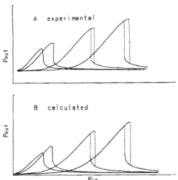
1 .0ith and 1 .3ith. Fig. 2(a) presents several of the bistable
141
I
8 c a l c u l a t e d
I
Fig. 2. Experimental and calculated bistable behavior of the transmitted power. The master laser diode temperature was varied to change the ini- tial detuning (pa for the experimental curves. The full scale for P,, is 20
pW and the full scale for Po,, is 600 pW for both sets of curves. The parameters derived from the experimental data, and used for the calcu- lated plots, in order of increasing peak power, were A = 52,46.2, 32.2, 27; F = 100, 89, 62, 52; (pa = 0.25, 0.29, 0.60, 0.96; -P/I'A = 2.5, 3 . 3 , 2 . 9 , 3 . 7 . For this experiment we derived a value of 6 = 0.092/pW.
loops observed for the different values of cpo. These ob- servations were made at a pulse frequency of 5 Hz. Fig.
2(b) shows plots of simulations using (1)-(3) with the val- ues of cpo,
p,
A , and F deduced from the experimental curves. The values of A and F were derived from the points of peak experimental transmission; thus they and the derived r values vary between curves, being in reality functions of Po,,. The calculated curves match the exper- imental observations quite closely, indicating the success of the two-term NLFP model in describing this device operation. Slightly better agreement could be expected if the variation of A, F, andr
with Po,, were included. The experimental curves have a CW offset which is due to the spontaneous emission of the amplifier.We should note that a similar experiment was per- formed by Nakai, Ito, and Ogasawara [15] in which the master laser was excited by square pulses of 2-4 ps. They observed asymmetry in the frequency response of the am- plifier as the wavelength varied at constant power. We see evidence in their published data of the same bistable ef- fects which we describe above, but apparently they did not recognize these and did not report them.
If this device is operated at low-duty cycle with pulses rising significantly slower than the thermal excitation time, but falling substantially faster than the thermal re- laxation time, an interesting optical hysteresis occurs in which there is distinct switching from the high to the low state, but no possibility for switching back to the high level. In this case the NLFP behavior during the rising edge and plateau of the input pulse is described by ( l ) , but during the falling edge of the pulse the bpi, term is replaced by a constant term pPin ( maximum). The pivot point for TL is ( cpo, -O/I') for the rising edge, but is
142 IEEE JOURNAL OF QUANTUM ELECTRONICS, VOL. 25, NO. 2, FEBRUARY 1989
(d)
Fig. 3. Optical hysteresis resulting from very slow relaxation of P,, phase contribution. Left diagrams show TA and TL intersections in ( q , T ) space as in Fig. l(c); those on the right show Po,, versus P,, as in Fig. l(d). For increasing P , , the pivot point is (I.,,. - b / r ) , labeled point 1. For falling P , , the P,, contribution retains its maximum value so that the pivot point is (96, 0 ) , labeled point 2. (a), (b) The maximum P,, is sufficient to switch the device to low transmission level, but relaxation takes place only at low transmission. No switch-off occurs. (c), (d) The maximum P , , reaches the bistable region of operation but is insufficient to reach the switching point. Switching to low transmission occurs as the intensity falls. If P , , has not reached the bistable region then ( ~ 6 lies under the peak of the transmission curve and hysteresis occurs without switch- ing.
the input determines cp;:
cp; = cpo
+
Bpi,( maximum). ( 6 )Fig. 3 illustrates this type of behavior for two different values of peak input power. In the case of Fig. 3(a) and (b) Pin rises to a level sufficient to switch the transmission from a high to a low state, but the reduction of Pin occurs over the range of powers for which TL has only one inter- section with TA. Thus Pout must fall monotonically with- out a second switching. Fig. 3(c) and (d) represents the behavior for a different cpo. The change from rising to fall- ing input takes place at a Pi, value which provides three
intersections between TL and TA, thus the switching from high to low output states take place as the input falls. By pulsing iL with a triangle wave at 100 kHz, where the pulse rise time was 10 ps and the fall time faster than 1
ps, we have observed hysteresis very similar to Fig. 3(b). Some pPin contribution remained during the falling edge
of the pulse so that a small switch-up was observed, though this produced only a very small increase in the transmitted signal. By changing po the hystersis evolved to the form of Fig. 3(d). With further increase of po we could eliminate the switch-down entirely, so that hyster- esis without switching was observed.
IV. DISCUSSION A N D CONCLUSIONS An optical device with sharp threshold in the behavior of Po,, may be used as the basis of an optical logic gate.
Although the slow speed of the device we have described points deserve a brief mention. First, the shape of the de- vice response curve allows two (and multiple) input AND, NAND, NOR, and XOR functions to be represented in the transmitted power by selecting appropriate sets of Pin val- ues as input states. We have observed each of these by performing a simulated two-input experiment [ 161 using
the apparatus described above. Second, the contrast level (ratio of high to low output power) we observed for the simulated AND gate was 4.2 : 1, which compares favorably with the 5 : 1 value recently reported for a high contrast AND gate using a laser diode amplifier in conventional NLFP operation [ 171. (If the spontaneous emission power were eliminated in our experiment, we would observe a
13 : 1 contrast.)
For a nonlinear Fabry-Perot etalon that is modified from conventional operation to include a nonlinear cavity phase shift dependent upon the incident power, the nonlinear behavior of the transmission (and reflection) is substan- tially different from that seen in conventional operation. We have shown that if the phase shift due to incident power is opposite to that due to transmitted power (and if the ratio of the phase shift coefficient
/r
is large enough) then the hysteresis is opposite to that seen in conventional NLFP operation. We have demonstrated this behavior in an all-optical system using laser diodes as both source laser and NLFP, although this implementation is limited to low-speed operation.renders optical gates derived f r o m i t impractical. two
ACKNOWLEDGMENT
The authors are grateful to Prof. T.-H. Huang for pro- viding them with space in his laboratory and for the loan of equipment. R. S. Jameson thanks Prof. C.-S. Han and Prof. J. S. Shie for arranging for him to serve as visiting
Associate Professor at National Chiao Tung University. REFERENCES
[ l ] P. W. Smith, E. H. Turner, and B. B. Mumford, “Nonlinearelectro- optic Fabry-Perot devices using reflected-light feedback,” Opt. Lett., vol. 2, no. 3, pp. 55-58, Mar. 1978.
[Z] M. Okada and K. Takizawa, “Electrooptic nonlinear devices with two feed signals,” IEEEJ. Quantum Electron., vol. QE-15, pp. 1170-
1175, Oct. 1979.
[3] A. Feldman, “Ultralinear bistable electro-optic polarization modu- lator,” Appl. Phys. Lett., vol. 33, no. 3, pp. 243-245, Aug. 1978. [4] -, “Bistable optical systems based on a Pockels cell,” Opt. Lett.,
v o l . 4 . n o . 4 , p p . 115-117, Apr. 1979.
[5] H. M. Gibbs, Optical Bisfabiliry: Controlling Light with Light. Or-
lando, FL: Academic, 1985, p. 188.
[6] A device constructed in this way would have conventional counter- clockwise transmission hysteresis because the two contributions to cavity phase shift have the same panty.
[7] D. Sand, R. S . Jameson, and R. K. Hickernell, “Optical bistability on reflection with an InSb etalon controlled by a guided wave,” Opt.
Lett., vol. 9, no. 5, pp. 159-161, May 1984.
[8] See F . S . Felber and J. H. Marburger, “Theory of nonresonant mul- tistable optical devices,” Appl. Phys. Lett., vol. 28, no. 12, pp. 731- 733, June 15, 1976; and H. M. Gibbs, Optical Bistability: Confrol- ling Light with Light.
[9] M. Nakamura, K. Aiki, J. Umeda, and A. Yariv. “C.W. operation of distributed feedback GaAs-GaAIAs diode lasers at temperatures up to 300K,” Appl. Phys. Lett., vol. 27, no. 7, pp. 403-406, Oct. 1,
1975.
143
IEEE JOURNAL OF QUANTUM ELECTRONICS, VOL. 25, NO. 2, FEBRUARY 1989
l l U J t l l r u ~ h t v p c ~ e l c c c r ~ r ~ ~ c S s m r c u r r r l u c r o r P r o r l u c r s D a r u B o o k . T o k y o ,
Japan: Hitachi Ltd., 1985.
[ 1 1 1 H . C . Casey and M. B. Panish, Heterostructure Lasers, Part E : Ma- terials and Operating Characteristics. New York: Academic, 1978, p. 62.
[I21 D. Weaire, B. S . Wherrett, D. A. B. Miller, and S . D. Smith, “Effect of low power nonlinear refraction on laser-beam propagation in InSb,”
Opt. Letr., vol. 4 , no. 10, pp. 331-333, Oct. 1979.
[I31 By “employed independently” we mean that the optical power ab- sorbed to produce the electronic effect results in negligible heating and the temperature change induced to produce the thermal effect re- sults in negligible change in the electron-hole population.
[14] T. Mukai and Y. Yamamoto, “Gain, frequency bandwidth, and sat-
uration output power of AlGaAs DH laser amplifiers,” ZEEEJ. Quan- tum Electron., vol. QE-17, pp. 1028-1034, June 1981.
1151 T. Nakai, R. Ito and N. Ogasawara, “Asymmetric frequency re- sponse of semiconductor laser amplifiers,’’ Japan. J. Appl. Phys.,
vol. 21, no. 11, pp. L680-L782, Nov. 1982.
[I61 Rather than insert beam splitters and mirrors to divide the laser output into two beams and then recombine these as the NLFP input (as is done in [17]), we used a single input beam with P , , directly adjusted
to the levels representing application of zero, one and two equal power input beams (plus any required bias beam levels).
[I71 W. F. Sharfin and M. Dagenais, “High contrast, 1.3 micron optical
A N D gate with gain,” Appl. Phys. Lett., vol. 48, no. 22, pp. 1510- 1512, June 2 , 1986.