國
立
交
通
大
學
網路工程研究所
碩
士
論
文
一個以 NAT 擷取為主的環境下提昇同儕式網
路電視播放品質的方法
An Approach for Improving Playback Quality for P2P IPTV
in NAT Major Access Environment
研 究 生:李尚書
指導教授:陳耀宗 教授
一個以 NAT 擷取為主的環境下提昇同儕式網路電視播放品質的方法
An Approach for Improving Playback Quality for P2P IPTV in NAT
Major Access Environment
研 究 生:李尚書 Student:Shang-Shu Li
指導教授:陳耀宗 Advisor:Yaw-Chung Chen
國 立 交 通 大 學
網 路 工 程 研 究 所
碩 士 論 文
A ThesisSubmitted to Institute of Network Engineering College of Computer Science
National Chiao Tung University in partial Fulfillment of the Requirements
for the Degree of Master
in
Computer Science
August 2009
Hsinchu, Taiwan, Republic of China
一個以 NAT 擷取為主的環境下提昇同儕式網路電視播放品質的方法
學生:李尚書
指導教授:陳耀宗 博士
國立交通大學網路工程研究所
摘要
網路電視(Internet Protocol Television)是現今網路上一個方興未艾的服務,透過電 腦上線,使用者可以利用網路接收到影音串流的資料,進而觀賞世界各地的電視節 目。過去,網路電視服務業者採用網際網路上傳統的用戶伺服器(client-server)架構來 提供服務,也就是用伺服器以提供所有用戶所需要的串流資料,然而當用戶數量過大 時,服務業者將面臨可容納度及高成本問題。近幾年來同儕式(peer-to-peer)檔案分享 與網路電話的發展,證明了透過同儕式架構也可以在網際網路上有效的傳遞各式各樣 的資料內容。因此,許多同儕式網路電視已經實現在網際網路上。不過也產生了另外 一個問題:當網路轉址器(NAT)的使用者過多時,位於網路轉址器後面的使用者(NATed peer)無法直接分享自己的串流資料給其它位在網路轉址器後面的使用者,使得這些同 儕端點很容易造成搭便車問題(free rider problem)。
在本篇論文中,我們提出一個分組的方法來提高 NAT 擷取為主的的分享率。藉 由限制擁有公共 IP 位址端點彼此之間的傳輸連結性,以及對資料通道(data trunk)的適 當分配,來促使位在網路轉址器後面的使用者貢獻更多的資料在整個網路上。另外, 所提出的方法是很容易新增在現有的網路電視的軟體上,不需要大幅修改,是相當實 用且容易實現的。我們發展出一套模擬軟體以評估我們所提出的方法,數值結果顯示 我們所提出的方法能夠提高 NAT 使用者的分享率並改善影像播放的穩定性。
An Approach for Improving Playback Quality for P2P IPTV in NAT
Major Access Environment
Student:Shang-Shu Li
Advisor:Dr. Yaw-Chung Chen
Institute of Network Engineering
National Chiao Tung University
Abstract
Internet Protocol Television (IPTV) is a quickly growing Internet service. Through computer online, users can access the network service to receive video streaming data and watch TV programs from around the world. Traditionally, IPTV service provider adopted client-server architecture. However, when the client population grows up to a certain amount, it usually faces the scalability and high cost problems. Fortunately, the P2P file sharing success and VoIP application has proved that the P2P paradigm is an efficient solution to deliver many kinds of content over the Internet. Nowadays, P2P IPTV services have been popularly deployed on the Internet.
We may face the problem that there are more and more Network Address Translator (NAT) users, and peers behind NAT (NATed Peer) can not directly deliver its streaming data to other NATed peers. This situation easily leads to the so-called free rider problem.
In this thesis, we propose a “grouping” scheme to increase the share rate of NATed peers. By restricting transmission connectivity of those peers with public IP address and properly arrange data chunk delivery, we could allow NATed peer to contribute more data on the overlay network. We developed a simulation program to evaluate our proposed scheme. The numerical result shows that our proposed scheme is able to increase the share
rate of NATed peer and improve the video playback quality. In addition, our scheme can be easily added to the existing IPTV software. It’s practical and feasible for implementation.
Acknowledgement
First of all, I would like to express my sincerity to my advisor Prof. Yaw-Chung Chen for leading me into research area and enlarge my sight. In addition, Prof. Yaw-Chung Chen also provides me many useful suggestions and advices on the writing of this thesis duration. In addition, I am grateful to my good friends and lab-mates for their useful suggestions and valuable comments.
Finally, I would express my indebtedness to my dear parents, and my lovely girl friend, Yeh Tien Hung, for their love, inspiration and continuous support.
Contents
摘要 I
Abstract II Contents V Table List VII Figure List VIII
Chapter 1 Introduction ...1
1.1 Overview ...1
1.2 Motivation and Purpose ...3
1.3 Organization of the Thesis...4
Chapter 2 Background ...6
2.1 Peer-to-Peer Network ...6
2.1.1 Introduction to peer-to-peer computing ...6
2.1.2 Peer-to-peer models ...7
2.1.3 BitTorrent—A successful P2P file sharing application ...8
2.2 P2P IPTV System...10
2.2.1 Gossip algorithm ...10
2.2.2 Key models ...11
2.2.3 Basic operations ...13
2.1.3 Introduction to NAT ...15
2.3.2 NAT traversal techniques ...16
Chapter 3 Proposed Approach... 22
3.1 Design Philosophy ...22
3.2 Goal of the Proposed Scheme ...24
3.3 Introduction to Proposed Scheme ... 25
3.3.1 Basic scheme ... 25
3.3.2 Proposed scheme ... 26
3.4 Summary ...31
Chapter 4 Simulation and Numerical Results ... 32
4.1 Scenario and Simulation Setting ...32
4.1.1 Scenario ...32
4.1.2 Simulation setting ...33
4.2 Simulation Result ...34
4.3 Summary ... 37
Chapter 5 Conclusion and Future Works ... 38
Table List
Table 2.1 Network type distribution of CoolStreaming users ... 16 Table 4.1 P2P IPTV System Surrounding ... 33 Table 4.2 Peers’ Bandwidth Distribution ... 33
Figure List
Figure 1.1 Client-Server architecture ...2
Figure 1.2 P2P data delivery concept. ...3
Figure 2.1 Pure P2P Architecture ...7
Figure 2.2 Hybrid P2P Architecture ...8
Figure 2.3 Intermediate P2P Architecture ...8
Figure 2.4 BT architecture ...9
Figure 2.6 Basic operations in P2P IPTV system ... 13
Figure 2.7 NAT traversal by relaying ... 17
Figure 2.8: UDP hole punching with peers behind different NATs ... 19
Figure 3.1 Three states of peer behavior ... 25
Figure 3.2 Four possible combinations of transmission ... 27
Figure 3.3 The proposed scheme. ... 30
Figure 4.1 Relationship of continuity index and ratio of non-NATed to NATed peers. ... 34
Figure 4.2 Comparison of the duration of continuity index over 0.9 between two schemes 35 Figure 4.3 Comparison of average share rate of NATed peers. ... 36
Figure 4.4 Comparison of NATed peers that 300 non NATed peers can support. ... 36
Chapter 1 Introduction
IPTV (Internet Protocol Television) is a system capable of receiving and displaying a video stream encoded as a series of Internet protocol packets. With a computer online, everyone can watch real time TV program through the Internet. Based on Peer-to-Peer (P2P) architecture, IPTV system can be scaled up, but we also face some other problems such as peers behind NAT can’t share data directly with each other. This causes serious problem when system is filled with large portion of NATed peers. In this chapter, we give a brief description and problem statement. Then, we introduce our research motivation and purpose before discussion of the thesis.
1.1 Overview
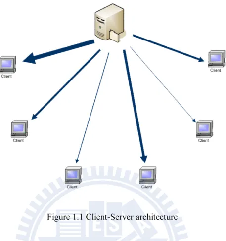
Along with broadband network’s vigorous development, live video streaming has become an emerging application over the Internet. In the past, IPTV service provider adapted Client-Server architecture just like other Internet services such as WWW, E-mail, BBS, and File Transfer Protocol (FTP). As Figure 1.1 shows, they employed a video server to broadcast streaming data to thousands of clients at the same time. A server could only support limit video streams due to the restriction of outbound bandwidth. For example, a server has 100Mbps and the video streaming rate is 500Kbps, then only 200 concurrent users can be fed (100Mbps / 500Kbps = 200). If the service providers want to scale up the system to support 100000~1000000 users, they have to employ much more servers with extremely large bandwidth. That is, the more IPTV users, the higher cost for ISP to pay.
Figure 1.1 Client-Server architecture
Fortunately, the P2P file sharing success and VoIP applications has proved that the P2P paradigm is an efficient solution to deliver all kinds of content over the Internet. The main concept of P2P technique is that all the peers form an overlay network and each peer is either a receiver or a supplier. Take BitTorrent (BT) file sharing system as an example, peers want to download a shared document. Each peer only needs to download some segments of the document and then exchange them. Finally, every peer can get all the segments to form a complete document. The advantage of P2P paradigm is when the number of users increases it will not add additional load to the server.
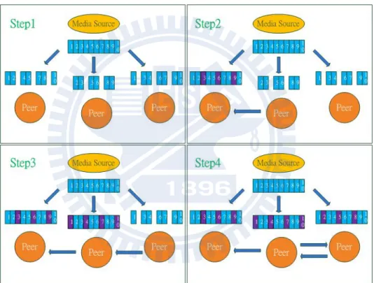
Figure 1.2 shows P2P data delivery concept. In step 1, each peer requests media server for video segments (also called chunks), some chunks may be lost during the process; In step 2, the left peer asks the middle peer the chunks that haven’t been received; In step 3, the middle peer requests the right peer for the needed chunks; In step 4, the right peer asks the middle peer the chunks that haven’t been received yet. Finally, each peer owns a
complete video document.
There are quite a few commercial P2P IPTV systems developed in recent years, such as PPLive [1], PPStream [2], CoolStreaming [3], and SopCast [4]. Most of them are proprietary systems. They do not release their source code and protocol scheme. Some researchers are still curious about the inside of the systems. Works have been done to analyze the systems by tracing their packets [5] and we can get a closer view in these IPTV systems.
Figure 1.2 P2P data delivery concept.
1.2 Motivation and Purpose
Data delivery through peer-to-peer indeed makes IPTV system more scalable and cost less on bandwidth, however here comes NAT traversal problem. Network Address Translation (NAT) causes well-known difficulties for P2P communications. Peers behind
NAT can’t share data directly with each other because the peers involved may not be reachable at any globally valid IP address. If P2P IPTV system is full of too many NATed peers (peers behind NAT), these peers are likely to become free riders. Free rider implies that a peer only downloads without uploading, and only receives data without delivery. We could image that if a system filled with a large portion of free rider and few peers contribute streaming data chunks, the system must be crash.
Several techniques have been proposed to resolve the NAT traversal problem. Session Initiation Protocol (SIP) users use Application Layer Gateway (ALG), TURN, STUN, UPNP, etc. to enable packet to traverse NAT. Some techniques statically assign NAT mapping table to enable incoming connection from outside to inside of NAT. Another technique requires the modification to TCP/IP protocol stack of OS (Operating System) kernel. These existing works require either special hardware or special middle server or administrator privilege or modification to existing kernel. Due to such kinds of inconvenience, the usage of these techniques is suppressed. In addition, TCP NAT traversal is much more difficult to implement than UDP NAT traversal and the success ratio of the former is especially low. However, many famous P2P IPTV systems use TCP to transport video data such as PPLive, PPStream, and CoolStreaming[4].
In this thesis, we propose a “grouping” scheme to increase NATed Peer’s share rate without NAT traversal. By restricting transmission connectivity of peer with public IP address (non-NATed Peer) and properly arrangement of data chunk delivery, we could improve share rate of those NATed Peers for streaming data on the overlay network.
1.3 Organization of the Thesis
operation of P2P IPTV system and some techniques of NAT traversal. In Chapter 3, we describe our proposed scheme in detail. The simulation results are presented in details in Chapter 4. Finally, we conclude the thesis and address some future works in Chapter 6.
Chapter 2 Background
In this chapter, we briefly describe the operation of P2P IPTV system and introduce some terms or QOS parameters. Then, we talk about NAT operation and NAT traversal problem. Finally, some NAT traversal technique will be addressed, too.
2.1 Peer-to-Peer Network
2.1.1 Introduction to peer-to-peer computing
Peer-to-Peer computing is the sharing of computer resources and services by direct exchange between systems. These resources and services include the exchange of information, processing cycles, cache storage, and disk storage for files. In spite the traditional client-server model is well known, secure, powerful, and reliable, it suffers from some other problems listed below: (1) Scalability is hard to achieve. It is not possible for a server to provide service to a huge number of clients due to the restriction of resources. (2) It presents a single point of failure. In client-server architecture, resources must be centralized in a specific machine which is called “server”. When server is broken all services are stopped. (3) Unused resources are left at the network edge. Actually not only server but also many other clients have some resource that we can utilize. This is the main reason that Peer-to-Peer computing comes up.
In P2P computing, peers are both server and client, peers can be service provider and receiver. Therefore we can fully utilize the whole resource of network to solve the scalability problem and balance the overload. Even a peer is broken or off-line, the peer can be easily replaced and P2P network can still work properly.
2.1.2 Peer-to-peer models
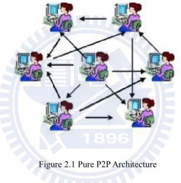
The P2P model can either be pure or it can be hybrid. In a pure model, there is no centralized server as Figure 2.1 shows. Peers acts as equals, merging the roles of clients and server. Examples of a pure P2P model include Gnutella and Freenet. Pure P2P model is easy to implement but hard to management. Peers don’t know where the target data is unless querying all other peers. It wastes the bandwidth and is not efficient.
Figure 2.1 Pure P2P Architecture
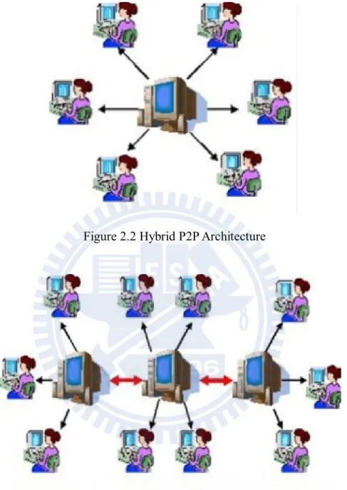
As Figure 2.2 shows, in a hybrid model, a server is approached first to obtain meta-information, such as the identity of the peer on which some information is stored, or to verify security credentials. From then on, the P2P communication is performed. Examples of a hybrid model include Napster and iMesh. The main advantage of hybrid model is easy to find peer to get target data because the data and peer information are recorded in central server.
There are also intermediate solutions with SuperPeers, such as KaZaa. SuperPeers contain some of the information that others may not have. Other peers typically lookup
information at Super Peers if they cannot find it otherwise as Figure 2.3 shows.
Figure 2.2 Hybrid P2P Architecture
Figure 2.3 Intermediate P2P Architecture
2.1.3 BitTorrent—A successful P2P file sharing application
BitTorrent (BT) [6] is a technology used for distribution of files much efficiently and fast. Since BT was developed in 2001, it has become more and more popular on file-sharing application and attracted a large number of users in the Internet world.
The most significant contribution of BT is breaking a file into many smaller pieces in fixed size, called chunks, for sharing. A user can download a file from other peers who own the different chunks of the file simultaneously. The novel idea greatly improves download efficiency and reduces lots of downloading time.
The “Tracker Server” in BT system logs who are downloading the file and helps peers find them out. Once a peer intends to download a file, it needs a “torrent” file which contains the file name, size, hashing information and the URL of the tracker server. As a result, a peer can make a connection to the tracker server by the indication of the torrent file.
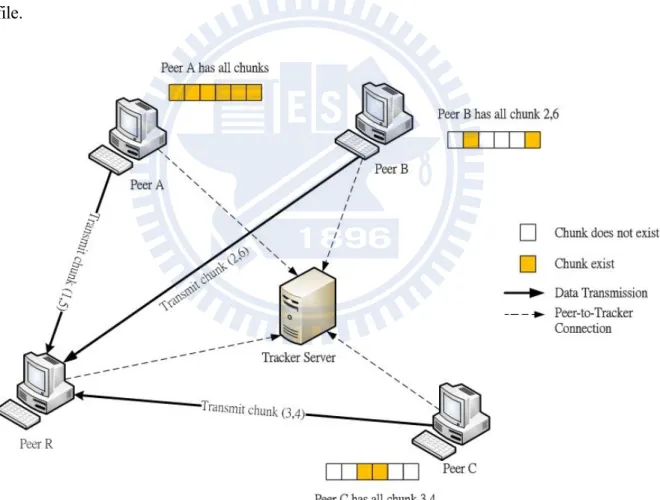
Figure 2.4 BT architecture
As Figure 2.4 shows, every peer in BT has to communicate with tracker server, such as peer A, B, C and R. Suppose that peer A is the “seed”, which is the source of the file. At the
moment peer R intends to download the file, it asks tracker server and get a response which indicates that peer A has all chunks, peer B has chunk 2 and 6, peer C has chunk 3 and 4. Now, peer R can receive chunk 1, 5 from A, chunk 2, 6 from B and chunk 3,4 from C simultaneously. With the aid of tracker server, peer can download different chunks of the file from different peers and greatly improve the efficiency on downloading a file.
2.2 P2P IPTV System
In early peer-to-peer file-sharing systems, files could be exchanged only when peers had the files in their entirety. However, since most users leave the system when the file download completes, a very small fraction of the total peer upload capacity was ever utilized. By fragmenting files into small pieces, BitTorrent allowed utilization of a large fraction of the total peer upload capacity. The idea of exchanging fragments also enabled supporting streaming applications over a peer-to-peer network and several peer-to-peer video streaming applications e.g. CoolStreaming and PPLive . In the following sub-sections, we will take a close look on P2P IPTV System and understand how it operates.
2.2.1 Gossip algorithm
Gossip algorithms have recently become popular solutions to multicast message in peer-to-peer systems [7], [8]. In a typical gossip algorithm, a node sends a newly generated message to a set of randomly selected nodes; these nodes do similarly in the next round, and so do other nodes until the message is spread to all. The random choice of gossip targets achieves resilience to random failures and enables decentralized operations. Usually, P2P IPTV system use gossip algorithm to perform membership management or partnership management. We will introduce in the following sub-sections.
2.2.2 Key models
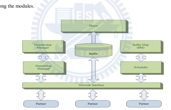
As shown in Figure 2.5, a node in P2P IPTV system has three key modules: (1) membership manager, which helps the node maintain a partial view of other overlay nodes; (2) partnership manager, which establishes and maintains the partnership with other nodes; (3) scheduler, which schedules the transmission of video data. For each segment of a video stream, a system node can be either a receiver or a supplier, or both, depending on data availability information, which is periodically exchanged between the node and its partners. An exception is the source node (the video server), which is always a supplier, and keeps alive. In this section, we discuss the basic modules in P2P IPTV system and how it interacts among the modules.
Figure 2.5 Key modules in P2P IPTV system.
A. Membership Management
Each node in P2P IPTV system has a unique identifier such as IP address or specific ID, and maintains a partial member list of the identifiers for the active nodes in the system. In a
some system, S randomly selects a deputy node D from its member list and redirects the new node to the deputy. The new node then obtains a list of partner candidates from the deputy, and contacts these candidates to establish its partners in the overlay. The redirection enables more uniform partner selections for newly joined nodes and minimized the origin node’s load. Although deputy node is good, some easily-implemented system only use origin node to do everything.
B. Partnership Management
In P2P IPTV System, a video stream is usually divided into segments of uniform length, and the segment availability information is recorded in the buffer, called Buffer Map(BM), of a node. Each node continuously exchanges its BM with the partners, and then schedules which segment is to be fetched from which partner accordingly. To design a properly Buffer Map is an important issue in P2P IPTV system. The size of Buffer Map, when to start playback……..etc, these affect the quality of service (QOS) of system service such as start-up delay, play-lag, or playback continuity.
C. Scheduling Algorithm
When we talk about scheduling in P2P IPTV system, we talk about how to schedule streaming segments to achieve the great benefit. That is, to decide which segment should be fetched from which partner. For a homogenous and static network, a simple round-robin scheduler may work well, but for a dynamic and heterogeneous network, a more intelligent scheduler is necessary. Two constraints we have to consider are: the playback deadline for each segment, and the heterogeneous streaming bandwidth from the partners. If the first constraint cannot be satisfied, the number of segments missing deadlines should be kept minimal.
D. Peer Adaptation
After establishing partnership with other peers and starting P2P video stream mechanism, a peer may seek more suitable new partners with larger network bandwidth or with less transmission delay for improving playback quality. For instance, some partners may leave the system suddenly or part of network backbone gets broken, these will interrupt the service connection between a peer and its partner. The mechanism described above is called Peer Adaption. The mechanism regarding how and when to perform peer adaptation is quite different among various P2P video streaming systems.
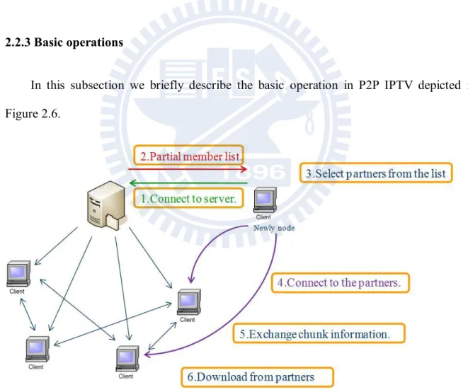
2.2.3 Basic operations
In this subsection we briefly describe the basic operation in P2P IPTV depicted in Figure 2.6.
Figure 2.6 Basic operations in P2P IPTV system
persists during the lifetime of streaming and its IP address is universally known. 2. The server or the deputy node gives its partial member list to the newly joined node. 3. The newly joined node selects limit partners from the list.
4. The newly joined node makes connection requests to all the partners selected and wait for response of each partner.
5. After connection establishment, the newly joined node and its partners exchange chunk information to see the distribution of streaming segments.
6. Download video streaming segments from partners.
2.2.4 QOS parameters
A. Start-Up Delay
Start-up delay is the time interval from when one channel is selected until actual playback starts on the screen. These delays (range from 10 sec to 2 min. [9]) are usually longer than provided by traditional television. Hence, the current P2P streaming technology does not provide users with the same channel-surfing experience as traditional television.
B. Playback Lag
The possibility of playback lags among peers is an unfortunate characteristic of a P2P IPTV system. The reason for playback lag is the deployment of the buffering mechanisms. Specifically, some peers watch frames in a channel minutes behind other peers. Thus, for example, in a live baseball game some peers will see a home run minutes after the real game.
Playback continuity is an important QOS parameter used to determine whether the video streaming is smooth enough. To evaluate continuity, sometimes we define a continuity index, which is the number of segments that arrive before or on playback deadlines over the total number of segments. If the continuity index reaches 1, it means all segments have arrived before the playback deadline. If the index is 0.9, it means 10% segments can’t be playback on time. In general, continuity index is less than 1.
D. Scalability
More users bring more business and hence more revenue, therefore, establishing a robust system to bear a large number of users is essential for a service provider. In P2P IPTV system, when we talk about that a system is scalable, it means that the system can bear a lot of peers with good video streaming quality.
2.3 NAT (Network Address Translator)
2.1.3 Introduction to NAT
Internet Protocol version 4 (IPv4) was designed in 70’s and is broadly used in Internet nowadays. However, the rapidly increasing number of Internet users leads to the insufficiency of IPv4 addresses. NAT was later used to allow many Internet users to access Internet simultaneously using one single IPv4 address. However, while providing the convenience of accessing the Internet, NAT also breaks the original Internet structure. Users outside NAT can’t use IP addresses to locate the users inside NAT, and users inside NAT can not provide Internet services to the users outside NAT. This causes a lot of difficulties for peer-to-peer communication, since the peers involved may not be reachable at any globally valid IP address.
Network Type Description Ratio
Direct-connect Peers have public addresses with both
incoming partners and outgoing partners. 10.9%
UPnP Peers have private address with both
incoming partners and outgoing partners. 18.7%
NAT Peers have private addresses with only
outgoing partners. 65%
Firewall Peers have public addresses with only
outgoing partners. 5.41%
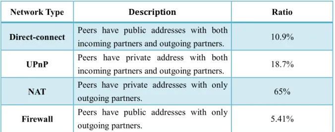
Table 2.1 Network type distribution of CoolStreaming users
In [10], it shows all kinds of network type of CoolStreaming users on 27 September, 2006, as in Table 2.1. We can see that over 70% users are NAT/Firewall users which can’t share data directly with each other. In other words, these users are “Free Riders”. This does really big damage to peer-to-peer application so that many NAT traversal techniques are proposed in recent years. In the rest of subsections we will briefly introduce some NAT traversal techniques and also point out the limitation and restriction. Finally, we will remind the motivation of our research and describe our proposed scheme in the next chapter.
2.3.2 NAT traversal techniques
A. Relaying
Relaying is the most reliable but least efficient method of P2P communication across NAT. It is simply to make the communication network structure look like standard client/server structure. As shown Figure 2.7, suppose two client hosts A and B have each initiated TCP or UDP connections to a well known server S with global IP address is
140.113.215.216 and port number is 1234. The clients reside on separate private networks, and their respective NATs prevent either client from directly initiating a connection to the other. Instead of direct connection, the two clients can simply use the server S to relay messages between them. For example, to send a message to client B, client A simply sends the message to server S along its already-established connection, and server S forwards the message to client B using its existing connection with B.
Figure 2.7 NAT traversal by relaying
Relaying works well as long as both clients can connect to the globally routable server. Its disadvantages are that it consumes the server’s computation power and network bandwidth, and communication latency between the clients is likely increased even if the server is well connected. Since there is no more efficient technique that works reliably on the existing NATs, therefore, if maximum robustness is the first concern and you hold a lot of resources then relaying is a fall-back strategy that can be considered. The TURN protocol [11] defines a method of implementing relaying in a relatively secure fashion.
B. UDP Hole Punching
Hole punching in UDP enables two clients to set up a direct peer-to-peer UDP session with the help of a well known server, called rendezvous server, even if the clients are both behind NATs. Hole punching assumes that the two clients, A and B already have active UDP sessions with a rendezvous server S. When a client registers to S, the server records two endpoints, private endpoint and public endpoint for the client. The private endpoint is the pair (IP address, UDP port) that the client believes itself to be used to communicate with S, and the public endpoint is the pair that the server actually observes. If the client is not behind a NAT, then its private and public endpoints should be identical.
Here we briefly describe how to establish Peer-to-Peer Sessions behind NAT. Suppose client A wants to establish a UDP session directly with client B. Hole punching procedure is presented as follows:
1. Initially A does not know how to contact B, so A send a request message to S asking for help establishing a UDP session with B.
2. S replies B’s public and private endpoints to A and uses its UDP session with B to send B a connection request message containing A’s public and private endpoints. Thus A and B know each other’s public and private endpoints after the above operation.
3. Once A receives B’s public and private endpoints from S, A starts sending UDP packets to both of these endpoints, and subsequently locks in whichever endpoint first response from B. Similarly, B does the same operation as A does.
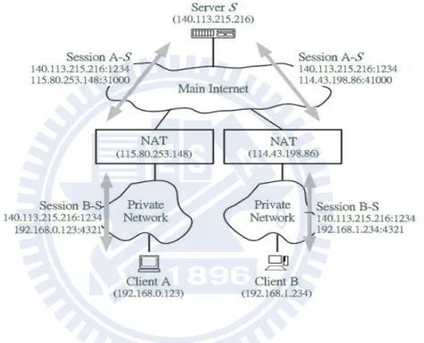
Before Hoe punching The Hole punching process After Hole punching Figure 2.8: UDP hole punching with peers behind different NATs
Take a simple scenario as an example. Suppose clients A and B have private IP addresses behind different NATs, as shown in Figure 2.8. A and B each initiated UDP sessions from their local port 4321 to port 1234 on server S. In handling these outbound sessions, NAT A has assigned port 62000 at its own pubic IP address, 115.80.253.148, and NAT B has assigned port 31000 at its IP address, 114.43.198.86. Through these sessions, A sends a registration message to S, A reports its private endpoint to S as 192.168.0.123:4321. S records A’s private endpoint and public endpoint 115.80.253.148:62000 observed by S itself. Similarly, when client B registers, S records B’s private endpoint as 192.168.1.234:4321 and B’s public endpoint as 114.43.198.86:31000.
Now client A follows the hole punching procedure described above to establish a UDP session directly with B. First, A sends a request message to S asking for help connection with B. S sends B’s public and private endpoints back to A in response, and send A’s public and private endpoints to B. A and B start trying to send UDP datagrams directly to each of
Consider A’s first message sent to B’s public endpoint, as shown in Figure 2.8. As this outbound message passes through A’s NAT, and NAT notices that this is the first UDP packet in a new outgoing session. The new session’s source endpoint(192.168.0.123:4321) is same as that of the existing session between A and S, but its destination endpoint is different. If NAT A is well-behaved, it preserves the identity of A’s private endpoint and translating all outbound sessions from private source endpoint 192.168.0.123:4321 to the corresponding public source endpoint 115.80.253.148:62000. This message “punches a hole” in A’s NAT for a session (192.168.0.123:4321, 114.43.198.86:31000). Once B’s request message reaches to A, the UDP session should be established. We seldom can predict the connection direction, this is not a problem in UDP, but in TCP, it’s a big trouble.
UDP hole punching works well in all kinds of NAT. STUN (RFC-3489) [12] is a UDP hole punching integration with port prediction and a stun server. Nowadays, most of peer-to-peer UDP NAT traversal problem could be solved through UDP hole punching.
C. TCP Hole Punching
TCP protocol is more complicated than UDP, it has flow control, congestion control and better reliability with 3 way handshake. TCP hole punching technique is similar to UDP hole punching, but the result is quite different. Since the standard Berkeley sockets API was designed around the client/server model, the API allows a TCP stream socket to be used to initiate an outgoing connection via connect(), or to listen for incoming connections via listen() and accept(), but not both. Further, TCP sockets usually have a 1-to-1 correspondence to TCP port numbers on the local host: after the application binds one socket to a particular local TCP port, attempts to bind a second socket to the same TCP port will fail. TCP hole punching has some other OS dependent or NAT dependent problems need to be solved [13], therefore, it’s not a good solution to TCP NAT traversal problem.
Until now, when facing the TCP NAT traversal problem, there is still not an effective and well-worked technique.
Chapter 3 Proposed Approach
As mentioned in previous chapters, peers in P2P IPTV system could share streaming data with each other to make the system more robust and scalable. This is the main advantage of peer-to-peer paradigm while NAT comes up to break the rule. Although NAT enables Internet users to use only one single IPv4 address to access Internet simultaneously, it destroys peer-to-peer architecture. Peers behind NAT can’t upload data segments directly to each other because of NAT property. Therefore, P2P IPTV system can’t reach its maximum benefit and gradually become client-server architecture. Is there a good solution to solve the problem? For UDP transmission, the hole punching could be used to solve NAT traversal problem. But for TCP, until now, there is no good solution that could be used to solve NAT traversal problem efficiently. Unfortunately, most of P2P IPTV system was implemented based on TCP, such as PPLive, PPStream, and CoolStreaming. Hence it is a question whether there exists any method that helps NATed peers improve the share rate and makes P2P IPTV system more attractive? Here we proposed an approach to improve QOS of P2P IPTV system without having to deal with NAT traversal.
In this thesis, we focus on mesh based P2P IPTV system because it is the major P2P architecture in current market. We will discribe our design philosophy and discuss our proposed scheme in detail in the following sections.
3.1 Design Philosophy
Based on NAT characteristic, peers behind NAT (NATed peers) can’t transmit data directly to each other, however NATed peers are able to upload data directly to peers which is not behind NAT (non-NATed peers). According to this observation, if we want to improve
Formula 3.1 Formula I of our design philosophy
the utilization of upload bandwidth of NATed peers, we can only improve its upload bandwidth utilization to non-NATed peers. Formula 3.1 shows the formula I of our design philosophy. Now we have a definite objective that is to improve NATed peer upload bandwidth utilization to non-NATed peer but how can we do? We know that no matter how much their bandwidth is, and no matter they are behind NAT or not, every well-behaved peer in IPTV system must get equal size of video streaming data if they have watched the same TV program for an equal time period. Besides, non-NATed peers can get streaming data segment from either non-NATed peers or NATed peers. Thus, we proposed a heuristic method: if we want to improve upload bandwidth utilization from NATed peers to non-NATed Peers, we have to suppress upload bandwidth utilization from non-NATed peer to non-NATed peers. That’s to say, we decrease the probability of data sharing among non-NATed peers to increase the probability of data sharing from NATed peers to non NATed peers. Doing so, we could prevent NATed peers from becoming free riders and make the IPTV systems more peer-to-peer like. Formula 3.2 shows the formula II of our design philosophy. Still, we encounter a new problem: how to suppress non-NATed peer’s upload bandwidth utilization to non-NATed peer? Or how to decrease the probability of non-NATed peers sharing data with each other?
Formula 3.2 Formula II of our design philosophy
3.2 Goal of the Proposed Scheme
Before introducing our proposed scheme, we should understand the goal we want to achieve. We expect certain improvements when our approach is added to an original P2P IPTV system. First of all, we want to improve NATed peers’ upload throughput
proportion. In P2P IPTV system, peers get data chunks from other peers that is either
NATed peers or non-NATed peers. Thus, increasing the NATed peers’ upload throughput proportion and decreasing the throughput proportion of non-NATed peer is the first objective we want to do. Besides, in real P2P system, each peer is functional equal, no one is specific, no server, no super peer, all of them do the same job. However, peers behind NAT are difficult to upload data to each other, they can only upload data to non-NATed peers. As a result, these NATed Peers gradually become free rider and the uploading tasks are all loading on non-NATed peers. Therefore, balance the system load is very important. If the above goals could be achieved, then system scalability improvement is obvious. In fact, scalability is the main concern for P2P IPTV system. The service provider can accept a little longer start-up delay or some playback lag, but they can’t tolerate the system with limited scalability. In addition, QOS enhancement is the final goal we want to achieve. We use continuity index to examine the video playback continuity and expect acceptable streaming quality even system is full of a large portion of NATed peers. We list four goals below as the conclusion of this section:
i. Improve NATed Peers’ upload throughput proportion. ii. Balance system load.
iii. Improve system scalability. iv. QOS enhancement
3.3 Introduction to Proposed Scheme
3.3.1 Basic scheme
We divide P2P IPTV peer behavior into three states. These are Closed, Start-Up and Steady states, as shown in Figure 3.1.
Figure 3.1 Three states of peer behavior
A user intends to watch P2P IPTV and launches the client application, this action triggers a New Joining operation and the user (peer) state transits from “Closed” to “Start-Up”. In the whole new joining process, the peer contacts the server with globally routable IP address. The server records the newly joined peer’s information including ID, IP
address, port number, etc in member list and send partial member list to the newly joined peer. Upon receiving the list from the server, the newly joined peer randomly chooses a fixed number of peers from the list and contacts them to establish its partners in the overlay. Once this newly joined peer obtains enough partners, it goes into Start-Up state. In this state, the first task peer has to do is collecting enough video chunks in the buffer for the playback. Peer then transfers from Start-Up state to Playback state after collecting enough smooth video segments. In Playback state, peer plays the video streaming and keeps receiving data chunks from its partners and also sending data chunks to those peers who made data request before. While peer leaves the overlay or switches channel, peer transits from Playback state to Closed state or to Start-Up state again as shown in Figure 3.1.
The traditional P2P IPTV scheme can work well when all joined peers are non-NATed peers which can share data with each other directly. However, today’s P2P overlay network is full of many NATed peers which can’t upload data as free as non non-NATed peers. As a result, this traditional P2P scheme will degenerate to client-server architecture and lose the benefits of peer-to-peer paradigm.
To solve the problem, we propose a heuristic approach to improve the share rate of the NATed peers. Further, it is easily implemented and added in the existing P2P IPTV system. In the following subsections we will describe our proposed scheme in more detail.
3.3.2 Proposed scheme
Peer classification
We classify P2P IPTV peers as non-NATed peer and NATed peer. As mentioned before, non-NATed peer is the peer with public IP address and can be directly uploaded data chunk by other peers. Oppositely, NATed peer is peer behind NAT, it usually owns private IP
address and can’t directly uploaded data chunk by other peers even by non-NATed peers. We use the following notation to classify these two kinds of peers.
Four possible combinations of transmission
Each peer in P2P IPTV system maintains a member list and a partner list which stored peers’ ID, IP address, and other important information. Peer connects to its partners and exchange buffer map to schedule which data chunk is to be fetched from which partner accordingly. There are four possible combination of transmission, non-NATed peers upload data to non-NATed peers, non-NATed peers upload data to NATed peers, non-NATed peers upload data to NATed peers, and non-NATed peers upload data to non-NATed peers. Only three of them can work properly but the last one is not possible for transmission. Figure 3.2 illustrates the four transmission combinations and the notation “smiled face” means it can properly work and notation “stop” means it does not work.
should and can only improve upload bandwidth utilization from NATed peer ▲ to non-NATed peer ●. We convert Formula 3.1 from text description to notation description as follows:
To improve ▲ upload bandwidth utilization, what we have to do is to improve ▲ ● upload bandwidth utilization. We know that a ● can get data chunks from either ▲ or ●, and the amount of video streaming data that a peer need to request is the same, it’s independent of which chunk from which peer. Thus, when a ● receives more data chunks from ●, then it receives less data chunks from ▲. In short, if we what to improve ▲ ● upload bandwidth utility, we have to suppress ● ● upload bandwidth utility. We convert Formula 3.2 from text description to notation description as follows, and we will describe our approach step by step in the following.
Our approach – Grouping Mechanism
First of all, we divide all non-NATed peers ● into M groups, group[0], group[1],……group[M-1]. Suppose M = 4, then we divide all non-NATed peers into group[0], group[1], group[2], and group[3]. It is easy to implement obviously, when a newly joined peer contact the server, the server will record two endpoints, private endpoint and public endpoint as mentioned before, then check if two endpoints are the same. If it is the
same, then the newly joined peer is a non-NATed peer and is marked as a member of group[0]. In the same way, the next non-NATed peer will be divided into group[1] and so on. What if the system comes an NATed peer, the server won’t divide it into groups or the server will divide it into group[4]. That’s to say, if M is four, we totally have five groups, four non-NATed groups and one NATed group.
Second, in P2P IPTV system, a video stream is divided into segments of uniform length called the segments chunks. Each chunk has its chunk ID to identify when the chunk should be played. Server is the source of the video streaming, it always has all the chunks available. In our approach, we let server deliver chunks to these M groups with the rule: if a chunk with chunk ID n+0, then the chunk will be delivered to group[0], if a chunk with chunk ID is n+1, it will be delivered to group[1],…. and if a chunk with chunk ID is n+M-1, it will be delivered group[M-1], n∈{0, M, 2M,….}. Take M = 4 as example, each chunk has its own chunk ID, chunk ID = 0, 1, 2, 3, 4, 5………. We force server deliver chunk with chunk ID = 0 only to group[0], chunk ID = 1 to group[1], chunk ID = 2 to group[2], chunk ID = 3 to group[3], chunk ID = 4 to group[0]. That is to say, non-NATed peer ● in group[K] can only receive chunks with chunk ID = n + k from server, n∈{0, M, 2M, …}.
Third, we have some restriction for peers finding partners. In original scheme, each peer in the system can invite any peers to be its partners. However in our proposed scheme, an non-NATed peer ● can only choose non-NATed peers in the same group and other NATed peers c as its partners. In short, it disallows non-NATed peer to invite non-NATed peer which is belong to other groups as its partners. As for NATed peer, it can only choose non-NATed peer as its partners just the same as the original scheme. We conclude the above steps as follows:
Streaming data is divided into chunks with its chunk ID.
Server delivers chunks to these M groups with the rule: chunk ID = n+0 group[0], chunk ID = n+1 group[1],……chunk ID = n+M-1 group[M-1]. That’s to say, ● in group[K] can only receive chunks with chunk ID = n+k from server, n∈{0, M, 2M,….}.
● can only choose ● in the same group and all other ▲ as its partners. ▲ can only choose ● as its partners.
Figure 3.3 The proposed scheme.
Now we use Figure 3.3 to explain our proposed scheme and discuss how to improve upload bandwidth utilization of NATed peers. In this figure, we set M to 4, thus, non-NATed peers ● are divided into 4 groups, from group[0] to group[3]. Peers in group[0] can only get chunks with ID 0,4,8…. from server, peers in group[1] can only get chunks with ID 1,5,9,….from server, peers in group[2] can only get chunks with ID 2,6,10,….from server, and peers in group[3] can only get chunks with ID 3,7,11,….from server. Besides, we
restrict that ● can only choose ● in the same group and all other ▲ as its partners. Through the restriction, we suppress non-NATed peer upload bandwidth utilization to non-NATed peer if they are in different groups and these non-NATed peers may get more chunks from NATed peers to improve the share rate of the NATed peers.
3.4 Summary
The grouping and partner selecting mechanism forces non-NATed peer to invite NATed peer as its partner in order to get the sufficient chunks. When there are only a small amount of NATed peers, the original scheme can work well. But if a P2P IPTV system is consisting of a large portion of NATed peers, adding the proposed approach to the original scheme will balance the system load and make the system more scalable. Most important, it is easy to implement.
Chapter 4 Simulation and Numerical Results
In this chapter, we present the simulation results and show figures to see what’s different between the origin scheme and the proposed scheme, as well as to see how much it has improved. From various aspects of view, we show that our proposed approach is practical and works well.
4.1 Scenario and Simulation Setting
We write a program in C/C++ language for building the P2P IPTV system and network environment. We adopt traditional P2P IPTV system scheme as our basic architecture in the simulation and add our proposed approach to the basic scheme. Also, we validate the performance and improvement through the simulation result.
4.1.1 Scenario
There are totally 1000 peers joining in the simulation.
When simulation starts, all peers join in the pseudo P2P IPTV system in 5 minutes.
No peers leave until simulation finish. Each peer can have at most 5 partners. Peer Adaption performs every 8 seconds.
To simplify the simulation, we use round robin scheduling. Peers are simply divided into NATed peers and non NATed peers.
System Surrounding
Server Upload Bandwidth 10 Mbps
Streaming Rate 500Kbps
Buffer Size 60 sec
Chunk Size 500 Kbit(1 sec)
Num of Group 4
Video Duration 30 min
Table 4.1 P2P IPTV System Surrounding
Peer Bandwidth Distribution
Upload Bandwidth Download Bandwidth Ratio of Peer
2000 Kbps 2500 Kbps 20%
1000 Kbps 1500 Kbps 60%
500 Kbps 1000 Kbps 20% Table 4.2 Peers’ Bandwidth Distribution
4.1.2 Simulation setting
Table 4.1 shows the system environment setting in simulation. We set server upload bandwidth to 10Mbps and streaming rate to 500Kbps. That means the server can only feed 20 clients at the same time using client-server paradigm. Usually, higher streaming rate means better video quality, and 500Kbps is enough for normal users. Buffer Size is set to 60 sec and chunk size is 500Kbit (1 sec). The Num of Group is the value of M which is set to 4, it means we divided non-NATed peers into 4 groups. Video Duration is the total length of the TV program and it means the total simulation time. We set it 30 minutes. Table 4.2 shows peers’ bandwidth distribution. Most of the peers’ bandwidth is set to the middle range and these could be NATed peers or non-NATed peers. From the bandwidth viewpoint, we treat NATed peers the same as non-NATed peers. Both of two types of peers have the same upload bandwidth and download bandwidth probability distribution.
4.2 Simulation Result
Figure 4.1 Relationship of continuity index and ratio of non-NATed to NATed peers.
Figure 4.1 shows the relationship of playback continuity and the ratio of non-NATed peers to NATed peers. In this experiment, there are 1000 peers joined in the system. For each simulation, we take different ratio of non-NATed peers to NATed Peers. For example, 500500F is a 3-tuple message which means 500 non-NATed peers, 500 NATed peers join in the system without our approach. 300700T means 300 non-NATed peers, 700 NATed peers in the system with our approach added. Further, in order to evaluate playback continuity, we define a continuity index, which is the number of segments that arrive before or on playback deadlines over the total number segments. We can observe that, when the number of NATed peers increases, the system continuity index decreases quickly. That is because these NATed peers are hard to share data with each other, and they always request data but seldomly provide data. Once the system is occupied by a large portion of NATed peers, then system will break down. With our approach, the system can bear more NATed peers (70%) and hold continuity index up to 0.9. However without our approach, the system can bear only (55%) NATed peers.
Figure 4.2 Comparison of the duration of continuity index over 0.9 between two schemes
The comparison of the duration of continuity index over 0.9 is shown in Figure 4.2. We can see the improvement when our proposed approach is adopted. When there are 450 non-NATed peers and 550 NATed peers in the system, the continuity index over 0.9 can lasted for 24 minutes without our approach, but with our approach it can lasted until the end of the simulation (30 min). Further, when the system’s NATed peers reach 700 and only 300 non-NATed peers joining in, the duration of continuity index over 0.9 is less than 9 minutes but with our approach it still can lasted over 30 minutes. We have to admit that the simulation results vary from different simulation settings, but at least in the same condition our proposed scheme features much better performance in simulation.
The next simulation was designed to examine whether the average share rate of NATed peer can rise up when our proposed approach is used. If we can’t increase the share rate of NATed peer, what we have done is in vain. Gratefully, Figure 4.3 shows the comparison of the average share rate of NATed peers. As comparing 450550F with 450550T, the value of share rate ranges from 0.22 to 0.37 and it is enhanced over 68%. As comparing 300700F with 300700T, we have more than 52% enhancement. These results show that our approach
is feasible and practical. Let’s compare Figure 4.2 with Figure 4.3, the duration of continuity index over 0.9 is positive related to the average share rate of NATed peers. In conclusion, if the NATed peers only contribute a small portion of data, it will affect the system performance and cause the system to fail.
Figure 4.3 Comparison of average share rate of NATed peers.
Figure 4.4 Comparison of NATed peers that 300 non NATed peers can support.
peers (ex:300), how much NATed peers they can bear and the system can still work well. What we mean “work well” is: during the 30 min simulation, the continuity index are always over 0.9. The result shown in Figure 4.4 demonstrates that without our approach, 300 non-NATed peers can only bear 450 NATed peers, however with our approach, 300 non-NATed peers can bear 700 NATed peers in system.
Finally, Figure 4.5 shows comparison of period throughput between 300700F and 300700T. The low throughput of NATed peers will encumber the throughput of non NATed peers and therefore encumber the whole system throughput.
Figure 4.5 Comparison of period throughput between 300700F and 300700T.
4.3 Summary
According to the above experiments, we observe that to increase the share rate of NATed peer is quite important. It helps the whole system operate smoothly with better scalability. Our proposed scheme can enhance NATed peers’ share rate over 50% and can support more NATed peers with a fixed number of non-NATed peers. The most important point is that our proposed scheme is easy to implement and without needing NAT traversal.
Chapter 5 Conclusion and Future Works
P2P IPTV system becomes more and more popular in recent years. However with the quickly growth of NATed peers, it causes the P2P architecture to degenerate into client-server architecture because these peers can’t share data directly with each other. Although there are some NAT traversal techniques like hole punching, TURN, …etc, it is inefficient or needs some modification on user’s local NAT. Although hole punching technique doesn’t have the above disadvantages, it only works well for UDP. Unfortunately, many famous P2P IPTV system such as PPLive, PPStream, and CoolStreaming use TCP for their data transfer.
In this thesis, we proposed an approach to deal with the problems of lower share rate of NATed peers. The main idea is reducing the probability of non-NATed peers’ data sharing with each other to increase the probability of NATed peers uploading data to non-NATed peer for the improving share rate of NATed peers. Thus, we proposed grouping mechanism and partner selecting mechanism to achieve the goal.
To evaluate the efficiency of our proposed scheme, we conduct a simulation environment implemented in C/C++ language. The result shows that our approach increases the share rate of NATed peers by over 50% and the improvement really causes the system more scalable as well as effectively balances the system load. In addition, our proposed scheme can be easily added into the existing P2P IPTV system. Only with a little modification, the original system can be upgraded.
Our proposed approach is still in simulation stage, we hope it could be applied in some existing P2P IPTV application. Because of the restriction of computing power, we can only simulate with a small number of peers (less than 1000). If we want to know how it works
with more peers joining in, we still need to develop a real P2P IPTV system with our approach and perform experiment on Internet.
References
[1] http://www.pplive.com. [2] http://www.ppstream.com.
[3] Zhang, X., J. Liu, et al. "DONet/CoolStreaming: A Data-Driven Overlay Network for Peer-to-Peer Live Media Streaming." Proc. IEEE INFOCOM 3:2102-2111,2005 [4] http://www.sopcast.com.
[5] Hei, X., C. Liang, et al. "A Measurement Study of a Large-Scale P2P IPTV System."
IEEE Transactions on Multimedia 9(8): 1672-1687, 2007
[6] Cohen, B., "Incentives Build Robustness in BitTorrent. " Workshop on Economics of
Peer-to-Peer Systems. 2003.
[7] Banerjee, S., Lee, S., Bhattacharjee, B., and Srinivasan, A. 2003. "Resilient Multicast Using Overlays. SIGMETRICS Perform. " Eval. Rev. 31, 1 (Jun. 2003), 102-113. [8] A. J. Ganesh, A.-M. Kermarrec, and L. Massoulie, "From Epidemics to Distributed
Computing." To appear in IEEE Computer Magazine, 2004.
[9] Hei, X. J., Y. Liu, et al. "IPTV over P2P streaming networks: The mesh-pull approach. " IEEE Communications Magazine 46(2): 86-92, 2008
[10] Xie, S., B. Li, et al. "CoolStreaming: Design, theory, and practice." IEEE Transactions
on Multimedia 9(8): 1661-1671, 2007.
[11] J. Rosenberg, R. Mahy, and C. Huitma, "TURN – Traversal Using Relay NAT," IEEE
Internet draft, Feb. 2004.
[12] J. Rosenberg, J. Weinberger, C. Huitema, and R. Mahy, "STUN – Simple Traversal of User Datagram Protocol (UDP) Through Network Address Translators (NATs)," IEEE
RFC 3489, Mar. 2003.
[13] B. Ford, P. Srisuresh, and D. Kegel, "Peer-to-Peer Communication Across Network Address Translators." Proc. USENIX Annual Technical Conference, April 10-15, 2005.