Intermetallic Formation in Sn3Ag0.5Cu and
Sn3Ag0.5Cu0.06Ni0.01Ge Solder BGA Packages with
Immersion Ag Surface Finish
TUNG-HAN CHUANG,1,2SHIU-FANG YEN,1 and HUI-MIN WU1
1.—Institute of Materials Science and Engineering, National Taiwan University, Taipei 106, Taiwan. 2.—E-mail: [email protected]
T h e i n t e r m e t a l l i c c o m p o u n d s f o r m e d i n S n 3 A g 0 . 5 C u a n d Sn3Ag0.5Cu0.06Ni0.01Ge solder BGA packages with Ag/Cu pads are investi-gated. After reflow, scallop-shaped -Cu6Sn5 and continuous planar -(Cu0.9Ni0.1)6Sn5 intermetallics appear at the interfaces of the Sn3Ag0.5Cu and Sn3Ag0.5Cu0.06Ni0.01Ge solder joints, respectively. In the case of the Sn3Ag0.5Cu specimens, an additional -Cu3Sn intermetallic layer is formed at the interface between the -Cu6Sn5 and Cu pads after aging at 150°C, while the same type of intermetallic formation is inhibited in the Sn3Ag0.5Cu0.06Ni0.01Ge packages. In addition, the coarsening of Ag3Sn pre-cipitates also abates in the solder matrix of the Sn3Ag0.5Cu0.06Ni0.01Ge packages, which results in a slightly higher ball shear strength for the speci-mens.
Key words: Sn3Ag0.5Cu, Sn3Ag0.5Cu0.06Ni0.01Ge, immersion Ag surface finish, intermetallic compounds
INTRODUCTION
Among the types of lead-free solders, the eutectic Sn-Ag-Cu alloy has drawn special attention due to its features of superior strength, ductility, and re-sistance to creep and fatigue.1Efforts have already been made to add a fourth element into the ternary Sn-Ag-Cu solder so that this alloy system can truly replace traditional Sn-Pb solders. A number of stud-ies have found that the excessive intermetallic growth at the interfaces between Sn-Ag-Cu solder and Cu substrate could be inhibited during the ag-ing2,3 and reflow processes4 with the addition of a small amount of Sb into the solder alloys. Anderson et al. reported that co-enhanced Sn-Ag-Cu solder joints exhibited the least sensitivity of shear strength to cooling rate due to the microstructure refinement in the solder matrix and at the solder/Cu substrate interface.5The effects of the addition of Bi on microstructure refinement and interfacial inter-metallics inhibition in Sn-Ag-Cu solder joints have also been ascertained by Zhao et al.6By further add-ing a trace amount of Ge into the bi-enhanced
Sn-Ag-Cu solders, Habu et al. demonstrated various im-proved mechanical properties, such as strength, thermal fatigue life, creep rupture time, and me-chanical shock resistance.7By adding 0.25 wt% Ce into a Sn3.8Ag0.5Cu solder, Chen et al. attained a 7-fold increase of its creep rupture life.8 In another recent study on the constitutive relations of creep behaviors for such rare-earth (RE) modified Sn-Ag-Cu solders, Chen et al. indicated that the creep stress exponents for Sn3.8Ag0.7Cu0.1RE solder joints were 8.2 and 14.6 at low and high stresses, respectively, both of which were higher than those for the case of undoped Sn3.8Ag0.7Cu.9
Sn3Ag0.5Cu0.06Ni0.01Ge is an innovative Pb-free solder developed by Japan’s Fuzi Electrical Co (Osaka, Japan). Ni was added into this alloy to im-prove its thermal fatigue resistance, while the addi-tion of Ge increases its wettability and decreases dross formation.10 The effects of Ni on the interme-tallic formation of Sn-Ag-Cu solders have also been studied by Chuang and Lin by dipping the Cu plates into liquid Sn-3.5Ag-0.7Cu and Sn-3.5Ag-0.5Cu-0.07Ni-0.01Ge solders at 250°C for 15 sec. They re-ported that the Ni-containing Sn-Ag-Cu solder pos-sessed much thicker interfacial intermetallic com-(Received May 24, 2005; accepted October 19, 2005)
pounds in comparison with the undoped Sn-3.5Ag-0.7Cu alloy.11–13However, after further aging from 105 to 150°C, the Sn-3.5Ag-0.7Cu solder exhibited a much higher intermetallic growth rate than the Sn-3.5Ag-0.5Cu-0.07Ni-0.01Ge solder.11–13 In this present study, the influences of Ni microalloying in Sn-Ag-Cu solders on intermetallic growth are
recon-firmed through the reflow and aging of Sn-3Ag-0.5Cu and Sn-3Ag-Sn-3Ag-0.5Cu-0.06Ni-0.01Ge solder joints in ball grid array (BGA) packages with Ag/Cu pads. Because the immersion Ag thin film on the Cu pad dissolves rapidly into liquid solder at the onset of the reflow process, it is between Sn-Ag-Cu solders and Cu pads that the interfacial reactions take place, which is similar to the prior cases investi-gated by Chuang and Lin.11
It is well known that the soldering reaction be-tween eutectic Sn-3.5Ag alloy and Cu substrate re-sults in the formation of Cu6Sn5 and Cu3Sn inter-metallic compounds at the interface. Accompanying the intermetallic growth, some of the Cu substrate dissolves into the solder matrix. Schaeffer et al. showed that the growth kinetics of interfacial inter-metallics was influenced by the amount of the dis-solved Cu.14Chada et al. further indicated that the rate of Cu dissolution could be described by a Nernst-Brunner equation.15 The dissolved Cu also caused the formation of Cu6Sn5intermetallics in the Sn-3.5Ag solder matrix, which could be suppressed by increasing the cooling rate.16 Anderson et al. re-vealed that the rapidly solidified Sn-3.6Ag-1.0Cu/Cu solder joints possessed a cellular/dendritic micro-structure decorated with fine intermetallic phases of Cu6Sn5and Ag3Sn.5The addition of the Co element Fig. 1. Temperature profile for the reflow process of the Sn-Ag-Cu
solder BGA packages with the immersion Ag surface finish de-scribed in this study.
Fig. 2. Microstructure of Sn-Ag-Cu solder balls before reflow: (a) Sn2Ag0.5Cu; (b) Sn3Ag0.5Cu0.06Ni0.01Ge.
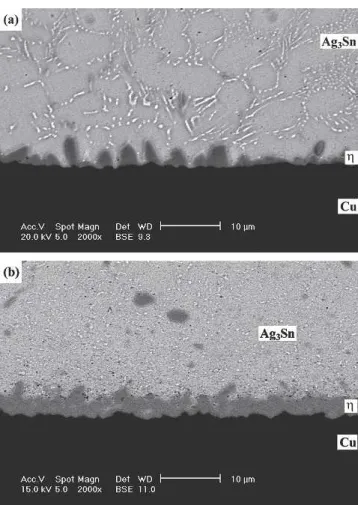
Fig. 3. Morphology of intermetallic compounds formed at the inter-faces of the as-reflowed solder joints: (a) Sn3Ag0.5Cu; (b) Sn3Ag0.5Cu0.06Ni0.01Ge.
Intermetallic Formation in Sn3Ag0.5Cu and Sn3Ag0.5Cu0.06Ni0.01Ge
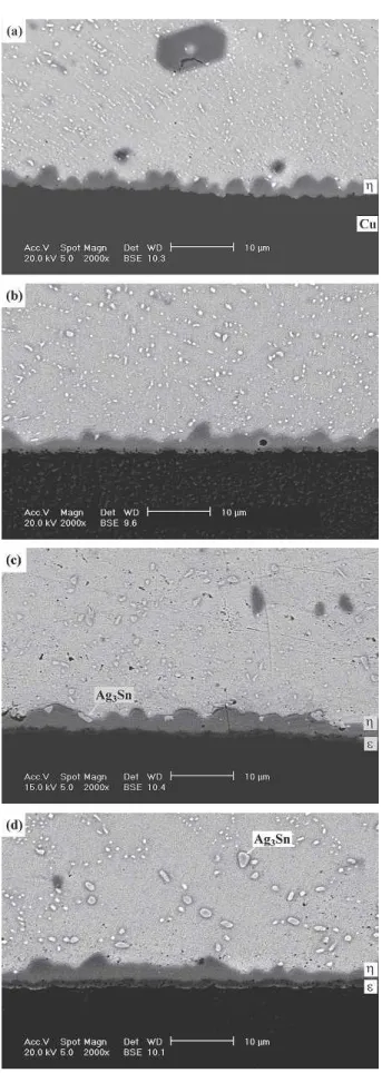
Fig. 4. Morphology of intermetallic compounds formed at the inter-faces of the Sn3Ag0.5Cu solder BGA packages with an immersion Ag surface finish after aging at 100°C for various times: (a) 100, (b) 300, (c) 700, and (d) 1000 hr.
Fig. 5. Morphology of intermetallic compounds formed at the inter-faces of the Sn3Ag0.5Cu solder BGA packages with an immersion Ag surface finish after aging at 125°C for various times: (a) 100, (b) 300, (c) 700, and (d) 1000 hr.
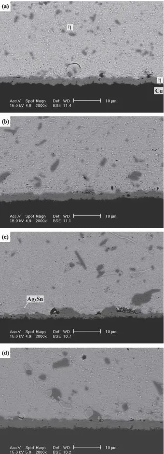
Fig. 6. Morphology of intermetallic compounds formed at the inter-faces of the Sn3Ag0.5Cu solder BGA packages with an immersion Ag surface finish after aging at 150°C for various times: (a) 100, (b) 300, (c) 700, and (d) 1000 hr.
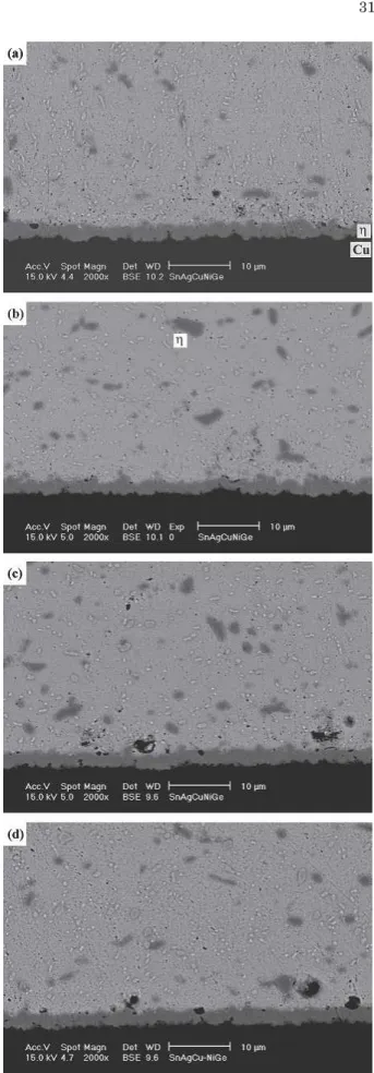
Fig. 7. Morphology of intermetallic compounds formed at the inter-faces of the Sn3Ag0.5Cu0.06Ni0.01Ge solder BGA packages with an immersion Ag surface finish after aging at 100°C for various times: (a) 100, (b) 300, (c) 700, and (d) 1000 hr.
Intermetallic Formation in Sn3Ag0.5Cu and Sn3Ag0.5Cu0.06Ni0.01Ge
Fig. 8. Morphology of intermetallic compounds formed at the inter-faces of the Sn3Ag0.5Cu0.06Ni0.01Ge solder BGA packages with an immersion Ag surface finish after aging at 125°C for various times: (a) 100, (b) 300, (c) 700, and (d) 1000 hr.
Fig. 9. Morphology of intermetallic compounds formed at the inter-faces of the Sn3Ag0.5Cu0.06Ni0.01Ge solder BGA packages with an immersion Ag surface finish after aging at 150°C for various times: (a) 100, (b) 300, (c) 700, and (d) 1000 hr.
into Sn-3.6Ag-1.0Cu solder was also reported by Anderson et al. to show a beneficial effect on its shear strength induced by refining the joint microstructure.
EXPERIMENTAL PROCEDURES The ball-grid array (BGA) package used in this study had 49 Cu pads on a FR-4 substrate, and the surfaces of the Cu pads were immersion-plated w i t h 0 . 2 - m t h i c k A g . S n 3 A g 0 . 5 C u a n d Sn3Ag0.5Cu0.06Ni0.01Ge (wt.%) solder balls 0.4 mm in diameter were dipped in rosin mildly acti-vated (RMA)-type flux, placed on these Ag/Cu pads, and then reflowed in a hot-air furnace. The tempera-ture profile for the reflow of both solder BGA pack-ages is shown in Fig. 1, where the soaking and peak temperatures were fixed at 190 and 240°C, respec-tively. A certain number of reflowed specimens were further aged at 100, 125, and 150°C for various times ranging from 100 to 1000 hr.
For metallographic observation via scanning elec-tron microscopy (SEM), the reflowed and aged BGA packages were cross-sectioned through a row of sol-der balls, ground with 2000-grit SiC paper, and then
Fig. 10. Growth thickness (X) of -(Cu0.9Ni0.1)6Sn5 intermetallic
compounds during the aging of (a) Sn3Ag0.5Cu and (b) Sn3Ag0.5Cu0.06Ni0.01Ge solder BGA packages as a function of the square root of time (t1/2).
Fig. 11. Arrhenius plots of the reaction constants (K) for growth kinetics of -(Cu0.9Ni0.1)6Sn5 interfacial intermetallics in the
Sn3Ag0.5Cu and Sn3Ag0.5Cu0.06Ni0.01Ge BGA packages.
Fig. 12. Growth thickness (X) of-Cu3Sn intermetallic compounds
d u r i n g t h e a g i n g o f ( a ) S n 3 A g 0 . 5 C u a n d ( b ) Sn3Ag0.5Cu0.06Ni0.01Ge solder BGA packages as a function of the square root of time (t1/2).
Intermetallic Formation in Sn3Ag0.5Cu and Sn3Ag0.5Cu0.06Ni0.01Ge
polished with 0.3-m Al2O3 powder. The chemical compositions of interfacial intermetallic compounds were analyzed with an energy-dispersive x-ray spec-trometer (EDX) in the SEM. For kinetic analysis, the maximum growth distances of convex scallops for each intermetallic layer were measured. The av-erage value of a minimum of 30 measurements for each soldering condition (per reaction temperature and time) was determined to signify the intermetal-lic thickness (X).
The bonding strengths of the solder joints in the BGA packages were measured via ball shear tests. The measurements were taken at a shear rate of 0.1 mm/sec and a shear height of 80m (about1⁄4of the
reflowed ball height). The fractography of the solder joints after ball shear testing was observed in the SEM.
RESULTS AND DISCUSSION
T h e m i c r o s t r u c t u r e s o f S n 3 A g 0 . 5 C u a n d Sn3Ag0.5Cu0.06Ni0.01Ge solder balls before reflow are similar, containing needle-shaped Ag3Sn and cluster-shaped Cu6Sn5 precipitates (Fig. 2). How-ever, intermetallic compounds showing distinct mor-phological differences appear at the interfaces of the Sn3Ag0.5Cu and Sn3Ag0.5Cu0.06Ni0.01Ge solder joints after reflow. In the case of the Sn3Ag0.5Cu BGA package, scallop-shaped-Cu6Sn5 intermetal-lics are formed at the solder/pad interface, as shown in Fig. 3a. On the other hand, a continuous pla-nar intermetallic layer with the composition of (Cu0.9Ni0.1)6Sn5 is found at the interface of the Sn3Ag0.5 Cu0.06Ni0.01Ge solder joint (Fig. 3b). In both cases, the immersion Ag thin film on the Ag/Cu pads has dissolved into the solder matrix. Further aging of the Sn3Ag0.5Cu BGA specimen at 100°C results in the growth of-Cu6Sn5intermetallic scal-lops, as shown in Fig. 4. It can also be observed in Fig. 4 that the needle-shaped Ag3Sn precipitates have resolidified into fine particles. When the aging temperature is increased to 125°C, the scallop-shaped Cu6Sn5 intermetallic layer becomes more continuous (Fig. 5). When the specimen is aged at 125°C for durations of more than 300 hr, a thin -Cu3Sn intermetallic layer is formed at the inter-face between the -Cu6Sn5 intermetallic scallops and the Cu pad. Figure 5 also reveals a large num-ber of voids present in the newly appeared-Cu3Sn intermetallic layer. In addition, those Ag3Sn precipi-tates in the solder matrix coarsen with the increase of the aging time, as shown in Figs. 4d and 5d. The formation of -Cu3Sn interfacial intermetallics be-comes much more conspicuous (Fig. 6) as the Sn3Ag0.5Cu BGA package is aged at 150°C. It is also shown in Fig. 6 that the interior of the-Cu3Sn intermetallic layer is filled with voids. Liu et al.17 and Vianco et al.18 have already reported the ap-pearance of Kirkendall voids in Cu3Sn intermetal-lics. Because the diffusion coefficient of Cu in
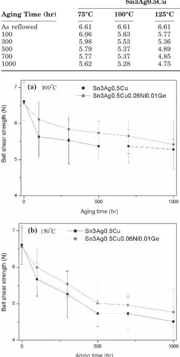
Table I. Ball Shear Strengths (N) of Sn3Ag0.5Cu and Sn3Ag0.5Cu0.06Ni0.10Ge BGA Packages with Ag/Cu Pads After Reflow and Aging Under Various Conditions
Aging Time (hr) Sn3Ag0.5Cu Sn3Ag0.5Cu0.06Ni0.01Ge 75°C 100°C 125°C 150°C 75°C 100°C 125°C 150°C As reflowed 6.61 6.61 6.61 6.61 6.56 6.56 6.56 6.56 100 6.06 5.63 5.77 5.67 6.21 6.11 5.96 5.99 300 5.98 5.53 5.36 5.26 6.11 5.84 5.64 5.54 500 5.79 5.37 4.89 4.73 6.05 5.74 5.15 5.01 700 5.77 5.37 4.85 4.73 6.05 5.65 5.05 4.96 1000 5.62 5.28 4.75 4.51 6.04 5.42 4.84 4.77
Fig. 13. Ball shear strengths of the solder joints in Sn3Ag0.5Cu and Sn3Ag0.5Cu0.06Ni0.01Ge solder BGA packages with Ag/Cu pads after aging at (a) 100°C and (b) 150°C for various times.
-Cu3Sn intermetallics is greater than that of Sn, as explained by Prinz and Wever,19the unbalanced in-terdiffusion causes Kirkendall voids to build up in the layer of Cu3Sn intermetallic compounds.
Figures 7–9 show the morphology of the interme-tallic compounds formed after the aging of the Sn3Ag0.5Cu0.06Ni0.01Ge BGA packages at various temperatures. The results indicate that the continu-ous -(Cu0.9Ni0.1)6Sn5 intermetallic planar layer grows with the aging temperature and time. How-ever, in contrast to what happens in the aging of the Sn3Ag0.5Cu specimens, the formation of the -Cu3Sn intermetallic phase is obviously inhibited. Even after aging at 150°C for prolonged times of 700 and 1000 hr, what can be observed (Fig. 9c and d) is simply a very thin layer of-Cu3Sn with Kirkendall voids. In addition, comparing Figs. 4d and 7d, it is evidenced that the Ag3Sn precipitates in the Sn3Ag0.5Cu0.06Ni0.01Ge solder matrix coarsened more slowly than those in the Sn3Ag0.5Cu speci-mens after the aging treatments.
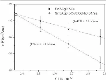
The growth thicknesses of -(Cu0.9Ni0.1)6Sn5 interfacial intermetallics formed during the aging of Sn3Ag0.5Cu and Sn3Ag0.5Cu0.06Ni0.01Ge solder BGA packages are plotted in Fig. 10 vs. the square root of time. The linear relation of each curve implies that the reaction is diffusion-controlled. Figure 10 also indicates that the Sn3Ag0.5Cu0.06Nu0.01Ge BGA packages possess thicker-intermetallic compounds at the early stage of aging. However, as the aging time increases, the growth rate of-intermetallics for the Sn3Ag0.5Cu packages become higher than that for the Sn3Ag0.5Cu0.06Ni0.01Ge packages. Figure 11 shows the calculation from the Arrhenius plots for reaction constants (K ⳱ ⌬x2/t), and the activation energies for the growth kinetics of -intermetallics are thus determined to be 42.8 ± 5.9 and 92.4 ± 8.4 kJ/mol for the Sn3Ag0.5Cu and Sn3Ag0.5Cu0.06Ni0.01Ge packages, re-s p e c t i v e l y . T h e a c t i v a t i o n e n e r g y f o r t h e Sn3Ag0.5Cu0.06Ni0.01Ge BGA packages is higher, which implies that the growth reaction of -interme-tallics in this case is much more sensitive to the aging temperature. The growth thicknesses of -Cu3Sn interfacial intermetallics in both solder BGA packages under various aging conditions also exhibited parabolic kinetics (diffusion-controlled), as shown in Fig. 12. However, the-Cu3Sn interme-tallics in the Sn3Ag0.5Cu0.06Ni0.01Ge packages grow much more slowly than those in the Sn3Ag0.5Cu specimens.
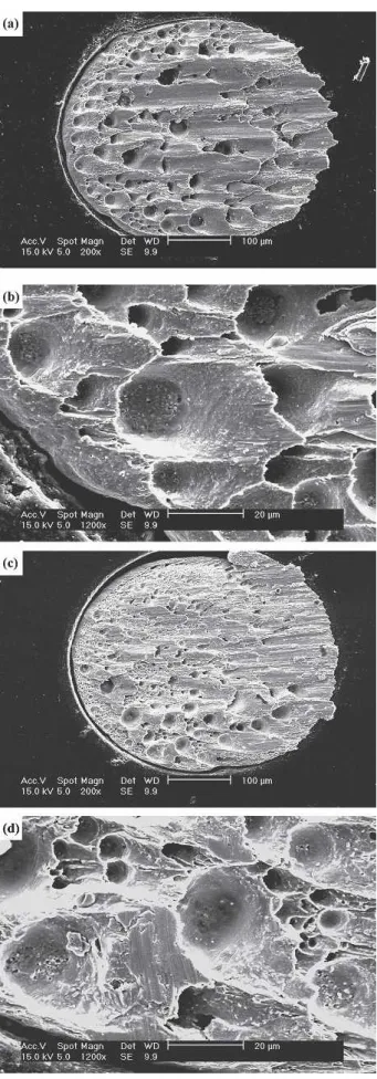
Ball shear strengths of both BGA packages after reflow and aging under various conditions are listed in Table I and plotted in Fig. 13. The re-sults show that the reflowed Sn3Ag0.5Cu and Sn3Ag0.5Cu0.06Ni0.01Ge BGA packages with the immersion Ag surface finish possess similar bonding strengths of 6.61 and 6.56 N, respectively. After ag-ing at 100 and 150°C, the ball shear strengths of both types of BGA packages decrease gradually with increased aging time. The bonding strengths of the Fig. 14. Typical fractography of the solder joints in BGA
pack-a g e s pack-a f t e r b pack-a l l s h e pack-a r t e s t s : ( pack-a , b ) S n 3 A g 0 . 5 C u ; ( c , d ) Sn3Ag0.5Cu0.06Ni0.01Ge.
Intermetallic Formation in Sn3Ag0.5Cu and Sn3Ag0.5Cu0.06Ni0.01Ge
Sn3Ag0.5Cu packages are slightly lower than those of the Sn3Ag0.5Cu0.06Ni0.01Ge specimens, which can be attributed to the higher tendency of Ag3Sn precipitates to coarsen. The fractography of the sol-der joints in both packages after the ball shear tests reveals the ductile fracture characteristic across the solder matrix (Fig. 14). However, fractographic analysis of the fractured Sn3Ag0.5Cu specimens confirms that the dimples are of a greater size and number than those in the Sn3Ag0.5Cu0.06Ni0.01Ge specimens. The higher tendency of Ag3Sn to coarsen should also be reflected in this phenomenon.
CONCLUSIONS
B e f o r e r e f l o w , S n 3 A g 0 . 5 C u a n d Sn3Ag0.5Cu0.06Ni0.01Ge solders possess similar microstructures. After reflow, scallop-shaped -Cu6Sn5 and continuous planar -(Cu0.9Ni0.1)6Sn5 intermetallics, two types of intermetallic compounds with different morphological characterizations, ap-pear at the interfaces of the Sn3Ag0.5Cu and Sn3Ag0.5Cu0.06Ni0.01Ge solder joints, respec-tively. With increases in aging time and tempera-ture, the -Cu6Sn5 intermetallic scallops in the Sn3Ag0.5Cu specimens become continuous, and an additional-Cu3Sn intermetallic layer is formed at the interfaces between the-Cu6Sn5 intermetal-lics and the Cu pads. A large number of Kirkendall voids can be observed to exist in the-Cu3Sn inter-metallic layer. For the Sn3Ag0.5Cu0.06Ni0.01Ge packages, the formation of the-Cu3Sn intermetallic phase accompanied with Kirkendall voids is inhib-ited. The growth of -intermetallics is diffusion-c o n t r o l l e d i n b o t h t h e S n 3 A g 0 . 5 C u a n d Sn3Ag0.5Cu0.06Ni0.01Ge packages, showing acti-vation energies (Q) of 42.8 ± 5.9 and 92.4 ± 8.4 kJ/ mol, respectively. The reflowed Sn3Ag0.5Cu and Sn3Ag0.5Cu0.06Ni0.01Ge BGA packages with the immersion Ag surface finish possess similar strengths of 6.61 and 6.56 N, respectively. After ag-ing at 75 and 125°C, the bondag-ing strengths of both packages decrease gradually with increased aging
time, which is attributed to the coarsening of Ag3Sn precipitates in the solder matrix.
ACKNOWLEDGEMENT
The authors express sincere thanks to National Science Council, Taiwan, for the sponsorship of this research under grant NSC-93-2216-E002-024.
REFERENCES
1. K. Zeng and K.N. Tu, Mater. Sci. Eng. R 38, 55 (2002). 2. B.L. Chen and G.Y. Li, 53rd Electronic Components and
Technology Conf. (Piscataway, NJ: IEEE, 2003), p. 1235.
3. X. Ma, F. Wang, Y. Qian, and F. Yoshida, Mater. Lett. 57, 3361 (2003).
4. B.L. Chen and G.Y. Li, Thin Solid Films 462–463, 395 (2004).
5. I.E. Anderson, J.C. Foley, B.A. Cook, J. Harringa, R.L. Terpstra, and O. Unal, J. Electron. Mater. 30, 1050 (2001). 6. J. Zhao, L. Qi, X.M. Wang, and L. Wang, J. Alloys Compd.
375, 196 (2004).
7. K. Habu, N. Takeda, H. Watanabe, H. Ooki, J. Abe, T. Saito, Y. Taniguchi, and K. Takayama, Proc. Int. Conf. Electron.
Environment, (New York: IEEE, 1999), p. 21.
8. Z.G. Chen, Y.W. Shi, Z.D. Xia, and Y.F. Yan, J. Electron.
Mater. 31, 1122 (2002).
9. Z. Chen, Y. Shi, and Z. Xia, J. Electron. Mater. 33, 964 (2004).
10. M. Yamashita, S. Tada, and K. Shiokawa (Fuzi Electric. Co.), “Solder Alloys,” U.S. patent 6,179,935 B1 (2001). 11. C.M. Chuang and K.L. Lin, J. Electron. Mater. 32, 1426
(2003).
12. C.M. Chuang, P.C. Shi, and K.L. Lin, Proc. Int. Conf.
Elec-tron. Mater. Packag. (New York: IEEE, 2002), p. 360.
13. C.M. Chuang, P.C. Shi, and K.L. Lin, J. Electron. Mater. 33, 1 (2004).
14. M. Schaeffer, W. Laub, R.A. Fournelle, and J. Liang, Design
and Reliability of Solders and Solder Interconnections, ed.
R.K. Mahidhara et al. (Warrendale, PA: TMS, 1997), p. 247. 15. S. Chada, R.A. Fournelle, W. Laub, and D. Shangguan, J.
Electron. Mater. 29, 1214 (2000).
16. S. Chada, A. Hermann, W. Laub, R.A. Fournelle, D. Shang-guan, and A. Achar, Soldering Surf. Mount Technol. 9, 9 (1997).
17. C.Y. Liu, K.N. Tu, T.T. Sheng, C.H. Tung, D.R. Frear, and P. Elenius, J. Appl. Phys. 87, 750 (2000).
18. P.T. Vianco, J.A. Rejent, and P.F. Hlava, J. Electron. Mater. 33, 991 (2004).