國立交通大學
國立交通大學
國立交通大學
國立交通大學
光電工程研究所
光電工程研究所
光電工程研究所
光電工程研究所
碩士學位論文
碩士學位論文
碩士學位論文
碩士學位論文
熔拉參數和
熔拉參數和
熔拉參數和
熔拉參數和色散
色散
色散機制
色散
機制
機制
機制對
對波長可調
對
對
波長可調
波長可調
波長可調短通
短通
短通光纖
短通
光纖
光纖
光纖
濾波器之
濾波器之
濾波器之
濾波器之影響
影響
影響研究
影響
研究
研究
研究
The Effects of Taper Parameters and
Dispersion Mechanism on Tunable Short
Wavelength Pass Fiber Filters
研
研
研
研
究
究
究
究
生
生 :
生
生
:
:
: 池昱勳
池昱勳
池昱勳
池昱勳
指導教授
指導教授
指導教授
指導教授 :
:
:
: 賴暎杰
賴暎杰
賴暎杰
賴暎杰
熔拉參數和色散機制對波長可調短通光纖濾波器之影響研究
熔拉參數和色散機制對波長可調短通光纖濾波器之影響研究
熔拉參數和色散機制對波長可調短通光纖濾波器之影響研究
熔拉參數和色散機制對波長可調短通光纖濾波器之影響研究
The Effects of Taper Parameters and Dispersion Mechanism on
Tunable Short Wavelength Pass Fiber Filters
研 究 生:池昱勳
Student:Yu-Syun Chih
指導教授:賴暎杰 老師 Advisor
:Yin-Chieh Lai
國 立 交 通 大 學
光 電 工 程 研 究 所
碩 士 論 文
A Thesis
Submitted to Institute of Electronics College of Engineering National Chiao Tung University
in partial Fulfillment of the Requirements for the Degree of
Master
In Electro-Optical Engineering
June 2009
Hsinchu, Taiwan, Republic of China
摘要
摘要
摘要
摘要
論文名稱 : 熔拉參數和色散機制對波長可調短通光纖濾波器之影響研究 校所別:國立交通大學光電工程研究所 頁數:1 頁 畢業時間:九十七學年度第二學期 學位:碩士 研究生:池昱勳 指導教授:賴暎杰 老師 關鍵詞: 光纖濾波器、熔拉光纖元件、波長可調、光纖色散 在本論文中我們利用熔拉技術來製作光纖濾波元件,透過將熔拉的區域浸於折射率 匹配油(色散材料)內來完成波長可調短通光纖濾波器的實驗製作。利用溫度控制器控溫, 可觀察到此濾波器對溫度的調變率為50nm/o c,濾波效率-1.2dB/nm,拒波效率達50dB。 我們也使用模擬軟體模擬出各種熔拉參數對濾波器的影響,包括熔拉直徑、熔拉均勻長 度、熔拉漸變長度等。根據實驗和模擬的對照,我們歸納了一組最佳的熔拉參數範圍。 最後,我們將原先的單模光纖換為雙被覆層光纖來製作出新的光纖濾波器。由於雙被覆 層光纖的外被覆層具有較低的折射率,根據色散機制可得知此濾波器可以有更佳的濾波 效率,而我們在實驗和模擬上也都一致地證實這個效應的存在。
ABSTRACT
Title:The Effects of Taper Parameters and Dispersion Mechanism on Tunable Short Wavelength Pass Fiber Filters
Pages:1 Page
School:National Chiao Tung University
Department:Institute of Electro-Optical Engineering
Time:June, 2009 Degree:Master
Researcher:Yu-Syun Chih Advisor:Prof. Yin-Chieh Lai
Keywords: Tapering standard single-mode fibers, Index matching liquids, Cut-off efficiency, Double cladding fibers, Dispersion mechanism
In the thesis, we demonstrate a new type of thermo-optic tunable short-wavelength-pass fiber filters (SPF) based on tapering standard single-mode fibers (SMF-28) to form fiber tapers, which are immersed in index matching liquids. Some of the significant results are the tuning efficiency can be 50nm/oc, the cut-off
efficiency can be -1.2dB/nm and the rejection efficiency can be 55 dB. The effects of various taper parameters on SPF have also been investigated by simulation to determine the optimum parameter range. We have also demonstrated a new structure of widely tunable LP01-C tapered fiber filters with an even higher cutoff slope based on
the tapered depressed-index outer ring fiber made from the double cladding fibers (DCLFs). The observed experimental results are explained by the dispersion mechanism and confirmed by theoretical simulation.
ACKNOWLEDGEMENT
在這兩年碩士班期間,我非常感謝賴暎杰老師對我百般的指導,使我對光纖波導光 學有更深的了解。也許有時候聽不懂老師的講解而一再發問,但老師從不曾失去耐心, 反而更加仔細地重新講解。此外,老師的學術風骨和待人處事更是我永遠敬佩和學習的 對象。 特別感謝徐桂珠學姐、陳南光學長對我的研究大力幫忙,讓我能順利完成論文研 究;項維崴學長、許宜蘘學姐、鞠曉山學長、郭立強學長、卓聖龍學長、張宏傑學長、 辛宸瑋學姐、莊佩蓁學姐對我的諄諄教導,使我能快速的熟悉實驗室運作,並提早進入 狀況。另外,我也感謝我的好同學秀鳳、佩芳、子翔,感謝你們在課業和實驗上給我支 持和協助;以及學弟柏崴、家豪、柏萱、榮宏、學妹姿媛,是你們帶給實驗室歡樂和趣 味,我永遠不會忘記實驗室出遊那段快樂的時光。最後要感謝我最摯愛的家人,以及其 他好朋友,謝謝你們在我背後給我支持的力量和關懷,使我有最大的勇氣面對艱難和挑 戰。以上,昱勳對於你們的鼓勵和祝福致上無限的感恩。CONTENTS
Page
Abstract (in Chinese)
iiiAbstract (in English)
ivAcknowledgement
vContents
viList of Tables
viiiList of Figures
ixChapter 1 : Introduction
1.1 Review of evanescent wave fiber tapercomponents 1 1.2 Dispersion mechanism of fiber taper components 2
1.2-1 Material dispersion 2
1.2-2 Waveguide dispersion 5
1.3 Structure and Material Constituents of Double Cladding fibers(DCLFs)
7
1.4 Motivation of This Work 10
1.5 References 11
Chapter 2 : Theory
2.1 Wave propagation in tapered single mode fibers 14
2.1-1 Local modes 14
2.1-2 Adiabaticity 18
2.2 Theminimum diameter of tapered fiber that can guide light
20 2.3 Working principle of optical tunable short pass filter
based on fiber tapering
23
2.4 References 26
Chapter 3 : Wideband
tunable short-pass single mode
fiber filter
3.1 Introduction 28
3.2 Experimental setup 28
3.3 Simulationparameter 31
3.4 Result & discussion 34
3.4-1 Experiment 34
3.4-2 Simulation 37
3.6 References 44
Chapter 4 : Wideband
tunable short-pass
double-cladding fiber filter
4.1 Introduction 45
4.2 Experimental & simulation setup 46
4.3 Result & discussion 48
4.3-1 Experiment 48 4.3-2 Simulation 51 4.4 Summary 55 4.5 References 56
Chapter 5 : Conclusion
Vita
58LIST OF TABLES
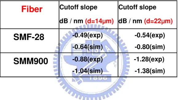
Table 1.1 Sellmeier parameters used in Fig1-1………..……...….3 Table 1.2 The material constituents of the DCLFs………....…...…8 Table 3.1 The cutoff slopes and dispersion slopes for different waist diameters of taper filters immersed in Cargille index matching liquid…..…...……...42 Table 3.2 Summary of each taper parameter………..………...43 Table 4.1 Cut-off slopes of SMM900 and SMF-28 with taper diameter 14 µm, 22 µm in experiment and simulation……….…….55
LIST OF FIGURES
Fig1-1 Sellmeier and Cauchy’s refractive index dispersion curves.………..…….4 Fig1-2 Structure of DCLFs……….………...8 Fig1-3 The refractive index distribution of the DCLFs……….…...9 Fig2-1 (a)A non-uniform fiber varies along its length and has refractive-index profile
n(x,y,z) (b) the approximate model of is serious section that matched taper shape………...………...16 Fig2-2 Effective index values for first five LP0m modes of finite cladding,
step-profile taper as functions of core guidance parameter V. Calculations are performed by varying ρ.Keeping core and cladding indices constant and equal to their value at wavelength 1 = 1.2 μm………..……….17 Fig2-3 Tapered single-mode fiber showing finite cladding and air as surrounding
medium………..………...18 Fig2-4 Transmission loss as a function of the taper fiber waist diameter d0 calculated
with Eq. (2.2.4) for different characteristic lengths of the transition length L (curves 1, 2, and 3) and d∞=1µm, and experimentally measured in L=10mm (curve 4)………...…………...22 Fig2-5 The refractive index dispersion curves. θ is the parameter that determines
the cut-off efficiency………..…………...……….24 Fig2-6 Refractive index dispersion curves for the index matching liquid and the
with the taper diameter of 30 µm by simulation……….………33 Fig3-4 Spectra transmission of SPF with tuning temperature (24oc~27oc)……....35
Fig3-5 Spectral transmission of a SPF with tuning temperature (24oc~27oc).…...35
Fig3-6 Different taper diameter d for SPF………..………..36 Fig3-7 MFD of 1250,1300(cut-off),1350nm for different taper diameters.(a) 1µm,(b)10µm,(c)26µm,(d)125µm……….………...38 Fig3-8 The effect of different uniform taper diameter d on SPF in simulation. L0 is
18 mm and τ is 6 mm………..……….39 Fig3-9 The effect of different taper length L0 on SPF when d is 40 µm and τ is 10
mm in simulation………...………..40 Fig3-10 Effect of different transition length τ on SPF when d is 40 µm and L0 is 15
mm in simulation………...………..41 Fig4-1 (Color online)Cross-sectional views of the SMM900 at different tapered diameters……….46 Fig4-2 Sketch for double cladding fibers (DCLFs). The red part is core and blue
part is inner cladding and yellow part (F-doped) is outer cladding
………..……….47 Fig4-3 Transmission spectra of the tapered SMM900 SPF at different temperature
and the taper diameter is 22 µm………...48 Fig4-4 Transmission spectra of the tapered SMM900 SPF at different taper diameter d with taper length L0 is about 5 mm……….………..49
Fig4-5 Measured spectral responses of tapered SMF-28 and tapered
SMM900 using A and B liquids with d=14 μm……….………..50 Fig4-6 Measured spectral responses of tapered SMF-28 and tapered
Fig4-7 Estimated RID of the fused silica, 1 mol. % F-doped silica, and Cargille liquids as well as the effective index of tapered SMF-28 in B liquid and taperedSMM900 in A liquid at different d………...…….51 Fig4-8 Mode field and refractive indices distribution in the taper waist of SMM900 at guided λ 1300 nm and taper diameter is 22 µm………..…..52 Fig4-9 Mode field distribution for SMM900 and SMF-28 at the taper diameter 22 μ
m and different wavelength (a)1250, (b)1350 nm………..…………...53 Fig4-10 Simulated spectral response for the tapered SMM900 immersed in A liquids
and SMF-28 immersed in B liquids, with d=14 µm and 22 µm……….54
Chapter 1
Introduction
1.1 Review of evanescent wave fiber taper components
Optical fiber components are essential for fiber-optic communication and sensing applications. Especially, since fiber-optic communication systems such as the local area networks (LANs) and metropolitan area networks (MANs) have been developed rapidly in recent years, optical fiber components have played very important roles in today’s networking systems. Optical fiber filters, for example, are important devices in wavelength division multiplexed (WDM) optical communication systems, in wavelength encoded or multiplexed fiber sensor systems, and also in fiber amplifier modules. [1.1] They can be made by chemical-etching[1.2-1.4],fused-tapering [1.5-1.9], side-polishing [1-10-1-13], and laser ablation [1-14] techniques to expose their evanescent field.
In this way,
to interact with the guiding light in the fiber core, we can gain access through the exposed evanescent field. In more details, a straightforward method is to remove a portion of the fiber cladding by chemical-etching, side-polishing or laser ablation until the evanescent field is accessed. Another method is to taper the fiber so as to expand the mode field distribution by using flame or laser heating[1-15].
Among these methods, the fusion-tapering technique is most widely adopted due to the easy, fast, and cost-effective fabrication process. However, the guided mode may be transferred into high-order modes through the tapered transition if it is not well tapered. [1-16].When the fiber core is tapered to a dimension of a few tens of micrometers, the mode field is expanded to the tapered fiber cladding which now serves as a new guiding core .One can then use dispersive liquids surrounded around the taper fiber to serve as the new cladding. The device formed by this way can be a short wavelength pass fiber filter (SPF) if the dispersion relations of the tapered fiber and the dispersive
liquids are properly designed. One can also tune the temperature of the dispersive liquids to change their dispersive curves for obtaining different cutoff wavelengths. The SPF can be used to achieve S-band Er+ fiber amplifiers and fiber lasers by using the conventional silica-based erbium-doped fibers. It also has the advantages of low insertion loss and wide tunability.
1.2 Dispersion mechanism of fiber taper components
The dispersion property of an evanescent wave fiber filter component is important for determining its spectral characteristics. The causes of dispersion can be divided into two categories, material and waveguide dispersion. In general, the material dispersion comes from the material dispersion properties of the fiber material and the external medium while the waveguide dispersion results from the waveguiding fiber structure. For fiber filter devices studied here, the relative refractive index difference of the fiber waveguide changes with the variation of wavelength through the material and waveguide dispersion. Therefore, the spectral responses will also vary accordingly. These influences are important when a wide range of wavelengths are considered.
1.2-1 Material Dispersion
When the refractive index varies with the wavelength of light, we call it material dispersion. The material dispersion of glass can be expressed by Sellmeier equation. The formula is valid at frequencies far from material resonance:
and infrared:
(1.2.2)
1
2 3 2 2 3 2 2 2 2 2 2 1 2 2 1 2λ
λ
λ
λ
λ
λ
λ
λ
λ
−
+
−
+
−
=
−
A
A
A
n
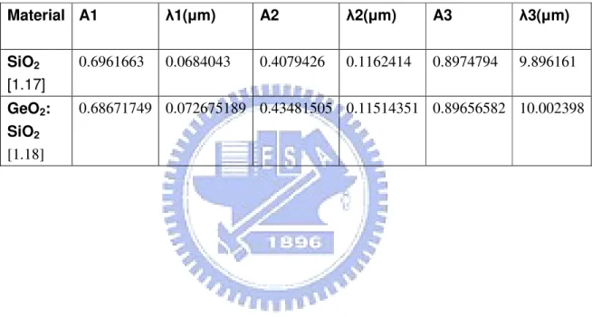
Eq(1.2.2) is plotted in Fig1-1 for pure silica and for 4.1% germania-dopedsilica, using the empirically determined Sellmeier coefficients given in Table 1.1[1.17-1.18].
Table 1.1 Sellmeier parameters used in Fig1-1
Material A1 λ1(µm) A2 λ2(µm) A3 λ3(µm) SiO2 [1.17] 0.6961663 0.0684043 0.4079426 0.1162414 0.8974794 9.896161 GeO2: SiO2 [1.18] 0.68671749 0.072675189 0.43481505 0.11514351 0.89656582 10.002398
0.2 0.4 0.6 0.8 1.0 1.2 1.4 1.6 1.8
1.44
1.45
1.46
1.47
1.48
1.49
1.50
R
e
fr
a
c
ti
v
e
i
n
d
e
x
Wavelength
(
µm
)
Fused Silica GeO2 :4.1mol%Fig1-1 Sellmeier and Cauchy’s refractive index dispersion curves.
When the material dispersion is un-matched between core and cladding, like in some special dispersive fiber [1.19-1.21], a fundamental-mode cutoff phenomenon will occur. Generally speaking, the index difference between the core and the cladding is usually almost wavelength independent. Therefore, all wavelengths longer than the second-mode cutoff wavelength can be well-confined to propagate in core with very low optical losses. However, the refractive index dispersion curves of the core and the cladding in a dispersive fiber can have an intersection point to induce the above mentioned fundamental-mode cutoff phenomenon [1.22], since the material dispersion is un-matched between the core and the cladding [1.19]. Consequently, the
highly dispersive. The energy bandgap (~9eV)[1.23] and the phonon energy (~1100 cm-1) of the Si-O bond in fused silica are higher than most of the covalently bonded optical polymers which makes the fused silica have flatter and steeper dispersion slope than the polymers at visible and near-infrared regions, respectively. Some polymers with intermolecular hydrogen bonds [1.24] have higher phonon energy and steeper dispersion slope than fused silica in the inner-infrared region. In ultraviolet regions, materials with stronger ionic bonds (Li-F or Mg-F) or a polar covalent bond (Si-F), i.e., a large value of electro-negativity difference will make the absorption blue-shifted toproduce higher bandgap energy [1.25] and flatter dispersion slope than fused silica. Therefore, dispersive materials with different phonon energies can be applied on evanescent-wave fibers to realize tunable fundamental-mode cutoff based on the discrepancy of material dispersion.
1.2-2 Waveguide Dispersion
In contrast to material dispersion, the waveguide dispersion due to the
waveguiding fiber structure is not so effective to affect the spectral
characteristics. In fused-tapered fibers, the length, diameter, strain, bending,
and dopant diffusion at the tapered region are the key issues for waveguide
dispersion. In general, the variation of these parameters will mainly vary the
dispersion slope of the guding mode. Usually, people discussed the influences
of waveguide dispersion on fiber devices based on special fibers [1.26-1.29].
However, the waveguide structure can also be locally changed to alter the
waveguide dispersion for light propagation and the spectral responses of the
fiber devices by using standard fibers [1.30-1.31]. The electromagnetic field
distribution is locally modified to vary the dispersion characteristics or to excite
the higher-order modes [1.31]. Therefore, novel fiber devices can be achieved
based on the variation of waveguide structure of the standard fiber in a small
local area. In this dissertation, since the dispersion measurement instruments
are not available in these cases, the influences of the variation of the
waveguide structure on the spectral characteristics are studied instead.
1.3 Structure and Material Constituents of Double Cladding fibers (DCLFs) Recently high power fiber lasers have played more and more important roles in micromachining, remote sensing, laser surgery, space communication, laser ignition, and so forth. With the advent of double-cladding fibers (DCLFs) and large mode area photonic crystal fibers, the laser output power under single transverse mode operation can be easily elevated to the Watt level with a length of a few meters [1.32]. The ultra-high gain efficiency comes from the long interaction length between the high power pump and the highly doped gain medium. In fact, the DCLF has a small rare-earth-doped core for single-mode signals and a larger fused silica core for multi-mode pump lights. The pump core can deliver very high pump power up to tens of Watts from multi-mode lasers and reflect the pump lights to intersect the signal core for many times so as to excite the doped ions efficiently for generating optical gain. Usually, the high power fiber lasers are very expensive due to the inclusion of highly doped DCLFs and the multi-mode diode lasers and thus high power fiber lasers with wide tuning range definitely have the economic advantages for many applications.
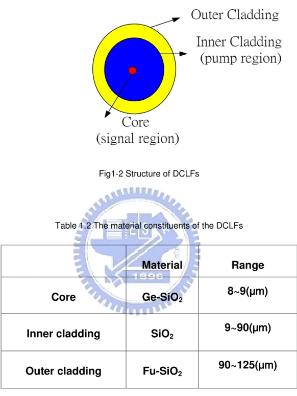
In our experiment, the DCLF of our work is SMM900 that is bought from Fibercore. The structure of the DCLFs is shown in Fig1-2.The signal wave travels in the core and the pump wave travels in the inner cladding (pump region) for cladding pump fiber lasers. The material constituents of the DCLFs are given in Table1.2. The refractive index distribution of the DCLFs is shown in Fig1-3.The material constituents of the core and the inner cladding are the same as convention single mode fibers. However, the material constituent of the outer cladding is Fu-doped silica. The refractive index of the outer cladding is much lower than the inner one because Fu is doped.
Fig1-2 Structure of DCLFs
Table 1.2 The material constituents of the DCLFs
Material
Range
Core
Ge-SiO
28~9(
μμμμm)
m)
m)
m)
Inner cladding
SiO
29~90(
μμμμm)
m)
m)
m)
Outer cladding
Fu-SiO
2Fig1-3 The refractive index distribution of the DCLFs
n
r(μm)
core
inner cladding
outer cladding
125 90 8~91.4 Motivation of This Work
This work presents new theoretical and experimental results on the thermo-optic tunable filters by using the tapered single mode fiber (SMF-28) immerged in dispersive liquids. We use simulation to predict the device cut-off wavelength and the tuning curve with respect to temperature changes. The optimal uniform taper diameter, taper length and transition length are also investigated by simulation.
Besides, we discuss the influence of the depressed-index outer ring on the fundamental-mode leakage loss in tapered double-cladding fibers. Accordingly, we can understand the effects of material dispersion on the characteristics of fundamental mode cutoff and expect the cutoff slope that is steeper than the previous single mode fiber taper filter.
1.5 References
[1.1] N. K. Chen, K. C. Hsu, H. J. Chang, S. Chi, and Y. Lai, “Tunable Er3+/Yb3+ co-doped fiber amplifiers covering S- and C-Bands (1460 ~ 1580 nm) based on discrete fundamental-mode cutoff,” in Proceedings of OFC 2006 conference Anaheim, USA, Mar. 5-10, 2006. OTHJ5.
[1.2] F. J. Liao and J. T. Boyd, “Single-mode fiber coupler,” Appl. Opt. 20, 2731-2734 (1981).
[1.3] S. K. Sheem and T. G. Giallorenzi, “Single-mode fiber-optical power divider: encapsulated etching technique,” Opt. Lett. 4, 29-31 (1979).
[1.4] C. D. Tran, K. P. Koo, and S. K. Sheem, “Single-mode fiber directional coupler fabricated by twist-etching techniques,” IEEE J. Quantum Electron. 17, 988-991 (1981).
[1.5] S. Kawasaki, and K. O. Hill, “Low-loss access coupler for multimode optical fiber distribution networks,” Appl. Opt. 16, 1794-1795 (1977).
[1.6] S. Kawasaki, K. O. Hill, and R. G. Lamont, “Biconical-taper single-mode fiber coupler,” Opt. Lett. 6, 327-329 (1981).
[1.7] D. Love and W. M. Henry, “Quantifying loss minimization in single-mode fibre tapers,” Electron. Lett. 22, 912-913 (1986).
[1.8] P. Kenny, T. A. Birks, and K. P. Oakley, “Control of optical fibre taper shape,” Electron. Lett. 27, 1654-1656 (1991).
[1.9] Kakarantzas, T. E. Dimmick, T. A. Birks, R. Le Rouz, and P. St. J. Russell, “Miniature all-fiber devices based on CO2 laser micro structuring of tapered
fibers,” Opt. Lett. 26, 1137 (2001).
[1.10] A. Burgh, G. Kotler, and H. J. Shaw, “Single-mode fibre optic directional coupler,” Electron. Lett. 16, 260-261 (1980).
applications as liquid crystal clad fiber polarizers,” J. Lightwave Technol. 15, 1554-1558 (1997).
[1.12] V. Cryan, and C. D. Hussey, “Fused polished single mode fibre couplers,” Electron. Lett. 28, 204-205 (1992).
[1.13] Laminger and R. Zengerle, “Determination of the variable core-to-surface spacing of single-mode fiber-coupler blocks,” Opt. Lett. 28, 211-213 (1987). [1.14] J. Coyle Jr. et al., “Methods and apparatus for making optical fiber couplers,”
US patent no. 5,101,090 (1992).
[1.15] W. Wu, T. L. Wu, and H. C. Chang, “A novel fabrication method for all-fiber, weakly fused, polarization beamsplitters,” IEEE J. Photon. Technol. Lett. 7, 786-788 (1995).
[1.16] A. Birks and Y. W. Li, “The shape of fiber tapers,” IEEE J. Lightwave Technol. 10, 432-438 (1992).
[1.17] H. Malitson, “Interspecimen Comparison of the Refractive Index of Fused Silica.” Journal of the Optical Society of America, vol. 55, pp. 1205-1209, 1965. [1.18] W. Fleming, “Material Dispersion in Lightguide Glasses,” Electronics Letters,vol.
14, pp. 326-328, 1978.
[1.19] W. Yu and K. Oh, “New in-line fiber band pass filters using high silica dispersive optical fibres,” Opt. Commun., vol. 204, pp. 111-118, 2002.
[1.20] Morishita, “Optical fiber devices using dispersive materials,” J. Lightwave Technol., vol. 7, pp. 198-201, 1989.
[1.23] N. Saeta and B. I. Greene, “Primary relaxation processes at the band edge of SiO2,” Phys. Rev. Lett., vol. 70, pp. 3588-3591, 1993.
[1.24] Sui, M. Hikita, T. Watanabe, M. Amano, S. Sugawara, S. Hayashida, and S.Imamura, “Low-loss passive polymer optical waveguides with high
environmental stability,” J. Lightwave Technol., vol. 14, pp. 2338-2343, 1996. [1.25] Hosono, M. Mizuguchi, L. Skuja, and T. Ogawa, “Fluorine-doped SiO2
glasses for F-2 excimer laser optics: fluorine content and color-center formation,”Opt. Lett., vol. 24, pp. 1549-1551, 1999.
[1.26] Zengerle and O. Leminger, “Narrow-band wavelength-selective directional couplers of dissimilar single-mode fibers,” J. Lightwave Technol. LT-5, 1196-1198 (1987).
[1.27] J. Chung and A. Safaai-Jazi, “Narrow-band spectral filters made of W-index and step-index fibers,” J. Lightwave Technol. 10, 42-45 (1992).
[1.28] Monerie, “Propagation in doubly clad single-mode fibers,” IEEE J. Quantum Electron. QE-18, 535-542 (1982).
[1.29] A. Arbore, “Application of fundamental-mode cutoff for novel amplifiers and lasers,” in Optical Fiber Communication Conference OFC’05 (Optical Society
of America, Washington, D.C., 2005), paper OFB4.
[1.30] K. Chen, S. Chi, S. M. Tseng, and Y. Lai, “Wavelength-tunable fiber codirectional coupler filter based on asymmetric side-polished fiber coupler with local dispersive intermediate layer,” submitted to ECOC 2006 conference. [1.31] K. Chen and S. Chi, “Influence of a holey cladding structure on the spectral characteristics of side-polished endlessly single-mode photonic crystal fibers,” accepted by Opt. Lett. (2006).
[1.32] K. Furusawa, A. Malinowski, J. H. V. Price, T. M. Monro, J. K. Sahu, J. Nilsson, and D. J. Richardson, Optics Express 9, 714 (2001).
Chapter 2
Theory
2.1 Wave propagation in tapered single mode fibers
Tapering of a single-mode optical fiber leads to a loss of power from the fundamental core mode because of the departure from the translational invariance of the uniform fiber. As it propagates along the taper, the field is unable to change its distribution rapidly enough to keep up with the variation of the fundamental local mode which shape is determined by the local taper cross section. The power loss from the core mode is associated with bending of the phase front owing to coupling of the fundamental mode with higher order modes. This power couples to cladding modes in a finite-clad fiber.
Intuitively, one would expect loss to decrease with decreasing taper angle, so that, in principle, loss could be kept arbitrarily small by using a sufficiently small taper angle. However, for practical devices, such as fiber tapers and fused taper couplers, there is a practical limit to the smallest taper angle that can be achieved over a significant length. Furthermore, extremely long devices are difficult to package, as well as being more susceptible to environmental effects.
2.1-1 Local modes [2.1]
Fabrication of tapered fibers and devices using the fused taper technique entails stripping the protective coating or jacket. Accordingly, the cross-sectional profile anywhere along the taper consists of a core embedded in a finite cladding, which is
complete core-finite cladding-air waveguide.
A taper is approximately adiabatic if the taper angle is small enough everywhere to ensure that there is negligible loss of power from the fundamental mode as it propagates along the length of the transition.The fields and propagation constant within an approximately adiabatic taper of a single-mode fiber can be described accurately by those of the local fundamental mode, which conserves power as it propagates and is the solution to the wave equation with the geometry of the local cross-section. If E(x, y, z) denotes the modal electric field, where z is the distance along the taper and x, y are the transverse co-ordinates , then [2.4, Chap. 19]
)
1
.
1
.
2
(
}
'
)
'
(
exp{
))
(
,
,
(
ˆ
)
(
)
,
,
(
0∫
=
a
z
e
x
y
z
i
zz
dz
z
y
x
E
β
β
where a(z) and β(z) are, respectively, the modal amplitude and propagation constant at position z, and
eˆ
contains the transverse dependence. At each position z along the taper, the fundamental local-mode propagation constant and fields are evaluated by solving the boundary-value problem for the fundamental mode on an infinitely-long cylindrically symmetric fiber whose cross-sectional geometry and refractive-index profile match those of the taper, as illustrated in Fig2-1(a),(b).[2.4] This prescription also applies to all the higher order local cladding modes of the finite-cladding taper.Fig2-1 (a)A non-uniform fiber varies along its length and has refractive-index profile n(x,y,z) (b) the approximate model of is serious section that matched taper shape.[2.4]
If the fiber core diameter varies with tapering, the local V defined by
)
2
.
1
.
2
(
)
(
)
(
2
)
(
z
z
n
co2n
cl2V
=
−
λ
πρ
and decreases linearly with fiber core. As shown in Fig2-2[2.1], the abscissa V(z) is the local V-value along the taper, and the ordinate gives the values of the effective index neff for the first five LP0m modes by solving eigenvalue equation. The horizontal
dashed lines correspond to the core and cladding index values .As would be expected,
the values of neff for the high order LP0m modes all lie below the cladding index when
V(z) is below 0.84. We call these modes cladding modes because the finite cladding of produces air-cladding waveguide. However, the neff of Lp01 for V(z) behind 0.84 lies
Fig2-2 Effective index values for first five LP0m modes of finite cladding, step-profile
taper as functions of core guidance parameter V. Calculations are performed by varying ρ.Keeping core and cladding indices constant and equal to their value at wavelength 1 = 1.2 μm.[2.1]
2.1-2 Adiabaticity [2.1]
The first criterion for adiabaticity is length scale that must be much larger than the coupling length between the fundamental mode and the dominant coupling mode for power loss to be small [2.5-6].Accordingly, we define the local taper length-scale zt as
the height of a right circular cone with base coincident with the local core cross-section and apex angle equal to the local taper angle
dz d z) tan 1 ρ ( = −
Ω , as
illustrated in Fig2-3, where z is the distance along the taper, and ρ =ρ(z)is the local core radius. Because in practice Ω z( )<<1, then
(2 . 1. 3)
t
z
≈
ρ
The local coupling length between the two modes is taken to be the beat length zb =
zb(z), between the fundamental and second local modes, where
)
4
.
1
.
2
(
2
2 1β
β
π
−
=
bz
and β =1 β1(z) and β =2 β2(z) are respective propagation constants. It is intuitive that if zt >>zbeverywhere along the taper, then negligible coupling will occur and the fundamental mode will propagate approximately adiabatically with negligible loss. Conversely, if zt <<zb there will be significant coupling to the second mode.
Accordingly, the condition zt =zb provides an approximate delineation between
approximately adiabatic and loss tapers. This is equivalent to [2.5]
)
5
.
1
.
2
(
2
)
(
1 2π
β
β
ρ
−
=
Ω
A similar, but less general, condition has been derived to minimum loss in optical waveguide horns operating in the multimode regime [2.7].
2.2 The minimum diameter of tapered fiber that can guide light [2.3]
Decreasing the taper fiber diameter d to values significantly smaller than the radiation wavelength, λ, causes a dramatic growth of the transversal dimensions of the fundamental mode, which propagates primarily outside the microfiber.[2.4]
-However, for d/λ<<1, a negligibly small nonuniformity of the microfiber can completely kill the propagating mode. For a fixed wavelength, quite general physical assumptions determine the threshold for the diameter of the microfiber, below which the propagation of evanescent light along the taper fiber is impossible. Consider two modes having propagation constants β1(z) and β2(z).The coupling between these
modes is defined by the coupling coefficient R12(z)[2.4]. Usually, for optical waveguides, the transmission amplitudes between modes at the input and output of the fiber taper are expressed within the first-order perturbation theory as an integral,
' ' ' 12 12
( ) exp {
[ ( )
1 2( )]}
(2 . 2. 1)
zA
∞dz R
z
i
dz
β
z
β
z
−∞=
∫
∫
−
which is calculated numerically.[2.4,2.8].
However, the solution of a similar problem yielding an extremely simple result for
A12 in the adiabatic approximation was obtained in quantum mechanics in the early 1960s by Dykhne[2.9] and Landau.[2.10] Crucially, the Landau–Dykhne formula, which corrects the mentioned first-order approximation for A12 in the case of finite
nonuniformities, does not depend on the coupling coefficient R12(z) at all.
* 2 12
exp[
{
[
1( )
2( )]}],
12 12( 2 . 2 .2 )
r z zA
=
i
∫
dz
β
z
−
β
z
P
=
A
Consider the taper of the shape d(z)=d∞−(d∞−d0){1−[(z-z0)/L]2}-1,where d∞ and d0 are
the taper’s diameters at its ends and at the center.For a silica microtaper (with a refractive index of 1.45) with a small waist diameter d<<λ, one can find from Ref. [2.4] that
2 2 2
1
( )
z
2( )
z
12( ) 0.57 [ /
z
d
( ) ]exp [ 0.27
z
/
d z
( )]
( 2 . 2.3)
β
−
β
=∆
β
≈
λ
−
λ
where ∆β12(z) now represents the difference between the propagation constant of the
HE11 mode, β1(z), and the radiation threshold, β2(z)=2π/λ.Then the transmission loss
P found from Eqs. (2.2.4) depends on the taper waist diameter d0 double exponentially: 2 1/2 1/2 2 0 0 0
0.687
0.27
~ exp
exp
(2 .2 . 4)
(
)
L
P
d
d
d
d
λ
∞
−
−
−
where L represents the transition length.The fundamental mode propagates along the microfiber only if P<<1, while the condition P~1 corresponds to the threshold when it disappears. Figure2-4 shows the transmission loss P as a function of the taper fiber waist diameter d0 for radiation wavelength λ=1.55 µm.[2.3] It demonstrates the
dramatic threshold behavior of the transmission loss predicted by Eq. (2.2.4) (curves 1, 2, and 3) and shows no significant difference between the threshold values of the taper waist diameter for a typical L=10 mm and for a gigantic L=10 km.Note that the loss P is in the strongest double-exponent dependence only on the minimum taper waist diameter, d0. The dependence of P on the parameter d∞−d0, which determines the shape of the microfiber’s taper, is much weaker. Therefore it is reasonable to conclude that the specific shape of the taper as well as its characteristic length L does not significantly affect the value of the threshold diameter.For this reason smoothly deformed optical fiber tapers can have very small losses. However, losses dramatically increase with a thinning of the taper fiber down to a diameter much
smaller than the radiation wavelength.
Fig2-4 Transmission loss as a function of the taper fiber waist diameter d0 calculated
with Eq. (2.2.4) for different characteristic lengths of the transition length L (curves 1, 2, and 3) and d∞=1µm, and experimentally measured in L=10mm (curve 4) [2.3].
2.3 Working principle of optical tunable short pass filter (SPF) based on fiber tapering
Tunable short-pass fiber filters (SPF) are advantageous for the S-band EDFAs [2.11] and for the high isolation WDM (de)multiplexers in triple-play (1310/1490/1550-nm) fiber-optic systems. A tunable short-pass fiber filter can be achieved by utilizing the fundamental-mode cutoff mechanism in which the lights with the wavelength longer than the cutoff wavelength λc can be highly attenuated to
obtain efficient filtering with sharp filter skirt. If we taper the single mode fiber adbabatically and let taper region immersed in a dispersive liquid such as Cargille index-matching liquid with the index nD = 1.456 and dnD/dT of -3.74 × 10⁻⁴ /°C. The
core effect vanishes because the taper fiber diameter is in a few tens of micro-order. Hence, the effective core is the original fiber cladding and the effective cladding is the outer surrounding. The effective index of waveguide is between fibers those of the original cladding and the outer surrounding, say dispersive liquids. For material dispersion, the effective index curve will cross the dispersive curve of the outer liquid, and the crossed point is referred as the cut-off wavelength(LP01-c). The filed which
wavelength is longer than cut-off will experience high loss and the field which wavelength is shorter than cut-ff will pass. The achieved cutoff efficiency is dependent on the material dispersion of the surrounding dispersive material and the waveguide dispersion of the tapered fiber device but typically the former dominates the cutoff efficiency more strongly than the latter when optical fields are mainly distributed over the guiding core. In the refractive index dispersion (RID) plot shown in Fig2-5, high cutoff efficiency is possible when the cross angle between the refractive index dispersion (RID) curves of the tapered fiber and the surrounding dispersive liquid is large [2.12].A larger cross angle can give rise to a steeper cutoff with higher rejection efficiency for the wavelengths longer than the cutoff wavelength.
Fig2-5 The refractive index dispersion curves. θ is the parameter that determines the cut-off efficiency.
Since the absorption phonon energy of the used dispersive liquid (Cargille index matching liquids) is so different from the high absorption phonon energy (~ 1100 cm-1)
of the silica fiber glass, the spectral response will be short-pass and the cutoff wavelength can be moved upward or downward, depending on the thermo-optic coefficients (dn/dT) of the dispersive material and the applied heating temperature [2.11]. The dn/dT of the index liquid is -3.74 × 10⁻⁴/°C, which is high enough to give
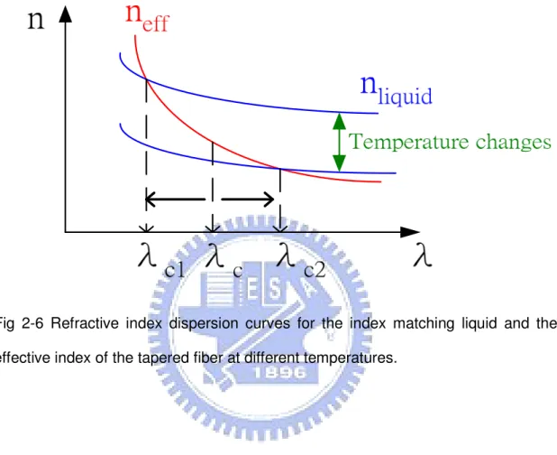
rise to high efficient temperature-tuning. Fig2-6 shows therefractive index dispersion
1.25
1.30
1.35
1.40
1.45
1.50
1.55
1.4450
1.4455
1.4460
1.4465
1.4470
1.4475
θθθθ
R
e
fr
a
c
ti
v
e
i
n
d
e
x
Wavelength(
µ
m)
Dispersive liquid(Cargille 1.456) Effective index of taper fiberinfluenced by the interaction length, the shape of the fused-tapered region [2.13] and the bending curvature of the tapered fiber.
Fig 2-6 Refractive index dispersion curves for the index matching liquid and the effective index of the tapered fiber at different temperatures.
2-4 References
[2.1] J.D. Love, W.M. Henry, W.J. Stewart, R.J. Black, S. Lacroix, and F. Gonthier, IEE PROCEEDINGS-J, vol. 138, no. 5, pp. 343-354 (1991)
[2.2] GONTHIER, F., HENAULT, A., LACROIX, S., BLACK, R.J., and BURES, J.: ‘Mode coupling in non-uniform fibres: comparison between coupled-mode theory and finite-difference beam propagation method simulations’, submitted to J. Opt. Soc. Am. A-B
[2.3] M.Sumetsky, Opt Lett vol. 31, no. 7, pp. 870-872, 2006.
[2.4] SNYDER, A.W., and LOVE, J.D.: ‘Optical waveguide theory’(Chapman and Hall, London, 1983)
[2.5] STEWART, W.J., and LOVE, J.D.: ‘Design limitation on tapers and couplers in single-mode fibres’. 5th Int. Conf. Integrated Opt. &Opt. Fibre Commun./ll th European Conf. Opt. Commun. Istituto Intemazionale delle Comunicazioni, Venice, Italy, 1985, pp. 559-562
[2.6] LOVE, J.D.: ‘Application of a low-loss criterion to optical waveguides and devices’, IEE Proc. J, 1989,136, pp. 225228
[2.7] MILTON, A.F., and BURNS, W.K.: ‘Mode coupling in optical waveguide horns’,
IEEE J. Quantum Electron., 1977, QE-13, pp.828-835
[2.8] D. Marcuse, Appl. Opt. 23, 1082 (1984).
[2.9] A. M. Dykhne, Sov. Phys. JETP 14, 941 (1962).
[2.12] N. K. Chen, S. Chi, and S. M. Tseng, “Wideband tunable fiber short-pass filter based on side-polished fiber with dispersive polymer overlay,” Opt. Lett. 29, 2219-2221 (2004).
[2.13] J. Villatoro, D. Monzon-Hernandez, and D. Luna-Moreno, “In-line tunable band-edge filter based on a single-mode tapered fiber coated with a dispersive material,” IEEE Photon. Technol. Lett. 17, 1665-1667 (2005).
Chapter 3
Wideband
tunable short-pass single mode fiber filter
3.1 Introduction
In this section, we will discuss the effects of taper parameters on temperature tunable short-pass single mode fiber filter (SPF) in the experiment and simulation. Parameters like the taper waist diameter, taper waist length, and transition length may change the cut-off efficiency since they will cause variation of the dispersion and mode field spreading in the taper waist. In other words, these parameter changes may affect the confinement of shorter wavelengths and the loss of longer wavelengths. Hence, we calculate the cut-off slope to evaluate the cut-off efficiency and get a proper parameter set to fabricate wideband tunable short-pass single mode fiber filters that can have best performance.
3.2 Experimental setup
One can taper an optical fiber of initial diameter d0 to a final diameter d by stretching
a uniformly heated fiber section of length Lo. The taper waist is predicted to vary with the elongation distance z as[3.1]
)
1
.
2
.
3
(
)
2
(
exp
0 0L
z
d
d
=
and the taper waist of length Lo. The taper transitions are exponential in shape[3.2]. The homemade tapering station depicted in Fig. 3-1 was implemented to fabricate the
rested on a sliding stand driven by a stepper motor. This process ensures that the flame identically heats each section of the fiber being tapered in each cycle of oscillation. Distance L0 can be exactly controlled. Therefore, the length of the uniform
waist of the tapered fiber is controllable. In our experiments the speed of the flame was set to approximately 0.2 mm/s, and L0 was in the range 10-20 mm range. At the
same moment when the flame starts to heat the fiber, the fiber is gently stretched in opposite directions. The pulling mechanism involves two sliding stands driven by stepper motors. The speed of the stand was approximately 0.055 mm/s. Total elongation distance z is the sum of the distances traveled by each stand, which can also be controlled precisely.
Fig3-1 Diagram of taper mechanism. d is donated as uniform taper diameter, and L0 is
Fig3-2 Real picture of the taper station
Standard telecommunication single-mode step-index fiber (SMF-28: Corning) was used to fabricate our samples. The fiber cladding-core diameters were 125/8.2 µm with a 0.13 numerical aperture, It is important to mention that this fiber is inexpensive and readily available. Before the pulling process began, the jacket was removed from the fiber over a section larger than L0. The fiber was cleaned with ethanol. By above
fabrication, we can make a low loss(<0.3dB) taper fiber and consider that the taper transition is adiabatically varying .Finally, we place the taper fiber in the V groove of glass substrate and inject the dispersive liquid (Cargille index matching liquids) with
3.3 Simulation parameter
In our simulation, we use Beam Propagation Method (BPM)[3.3-3.4] to simulate the performance of SPF by commercial software and discuss more details about the wave propagating in tapered fiber including transverse mode profile, the effective index of refraction and power monitored during wave propagation. BPM refers to a computational technique in electromagnetics, used to solve the Helmholtz equation under conditions of a time-harmonic wave. BPM works under the slowly varying envelope approximation, for linear and nonlinear equations. The Helmholtz equation is following as:
)
1
.
3
.
3
(
0
)
(
∇
2+
k
02n
2ψ
=
With filed written as:)
2
.
3
.
3
(
)
(
)
,
,
(
)
,
,
,
(
x
y
z
t
x
y
z
e
x
p
i
t
E
=
ψ
−
ω
Now the spatial dependence of this field is written according to any one TE or TM polarizations:
)
3
.
3
.
3
(
)
(
)
,
,
(
)
,
,
(
x
y
z
=
A
x
y
z
e
x
p
i
k
zz
ψ
.with the envelop A(x,y) following a slowly varying approximation,
)
5
.
3
.
3
(
)
4
.
3
.
3
(
2 2 2kA
z
A
A
k
z
A
<<
∂
∂
<
<
∂
∂
Now when the solution ansatz is inserted into the Helmholtz equation for simplification, one obtains the following equation:
)
6
.
3
.
3
(
)
,
,
(
2
)
,
,
(
)
(
02 2 2 2 2 2 2z
z
y
x
A
k
i
z
y
x
A
k
n
k
y
x
z z∂
∂
±
=
−
+
∂
∂
+
∂
∂
With the aim to calculate the field at all points of space for all times, we only need to compute the function A(x,y,z) for all space, and then we are able to reconstruct ψ(x,y,z). Since the solution is for the time-harmonic Helmholtz equation, we only need to calculate it over one time period. We can visualize the fields along the propagation direction, or the cross section waveguide modes. The master equation is discretized (using various centralized difference, crank nicholson scheme etc) and rearranged in a causal fashion. Through iteration the field evolution is computed, along the propagation direction. We set the taper transition to be exponential varying and get the output transmission versus the light wavelength. In addition, we use the transparent boundary condition [3.5-3.6] during simulation. Fig 3-3 shows the field with the wavelength of 1250 nm propagates to z axis in a taper fiber with the taper diameter of 30 µm by simulation. We can see the evanescent field arises in the taper waist.
Fig3-3 The field which wavelength is 1250 nm propagates to z axis in a taper fiber with the taper diameter of 30 µm by simulation.
3.4 Results & discussion 3.4-1 Experiment
In our measurement, a broadband white light source containing super-luminescent diodes spanning from 1250 to 1650 nm was launched into the measured fiber for performing measurement. The tapered fiber was heated by a TE-cooler to stabilize the temperature within 0.1°C. The refractive index of the surrounding index liquid decreases with the increasing temperature and in this way the temperature tuning can make the whole wavelength band from 1250 to 1650 nm become all-rejection or all-pass. Therefore, we use an optical spectrum analyzer to get the transmission data. Fig3-4 demonstrates the spectral transmission of a SPF with tuning temperature (24oc~27oc) and compare to the results of simulation. The
taper diameter d is 26 µm, and the taper length L0 is 18 mm, and the transition length
τ is 6 mm. We can see that the experimental results agree well with the simulation ones. The significant results are the tuning efficiency can be 50nm/oc, and cut-off
efficiency can be -1.2dB/nm and rejection efficiency can be 55 dB. For the last case, if we change d to 40 µm, and L0 to 20 mm and τ to 10 mm, the tuning efficiency can
improve to 58 nm/ oc and the cut-off efficiency can improve to -2dB/nm in our
Fig3-4 Spectra transmission of SPF with tuning temperature (24oc~27oc)
Fig3-5 Spectral transmission of a SPF with tuning temperature (24oc~27oc)
1250
1300
1350
1400
1450
1500
-50
-40
-30
-20
-10
0
T
ra
n
s
m
is
s
io
n
(d
B
)
Wavelenghth
(
nm
)
24oC 25 o C 26 o C 27 o Cd=40
µ
m
τ
=10mm
L
0=20mm
1250 1300 1350 1400 1450 1500 1550
-60
-50
-40
-30
-20
-10
0
27oc 26oc 25ocT
ra
n
sm
iss
io
n
(d
B
)
Wavelength(nm)
d=26um, τ=6mm, L0=18mmSimulation
Experiment
24ocHere, we will compare the effect of different taper diameter d on SPF in experiment. The result shows in Fig3-6. We can find the cut-off efficiency of shorter taper diameter is lower because the guidance of shorter wavelength becomes worse. However the rejection efficiency of larger taper diameter also becomes worse because the better confinement affects the longer wavelength loss.
Fig3-6 Different taper diameter d for SPF
1300
1400
1500
1600
-60
-50
-40
-30
-20
-10
0
T
ra
n
s
m
is
s
io
n
(d
B)
Wavelength(nm)
d=20
µ
m
d=26
µ
m
d=40
µ
m
3.4-2 Simulation
First, we discuss how mode field diameter (MFD) in the uniform taper waist of SPF varies with the taper diameter and wavelength. Fig3-7(a),(b),(c),(d) show the MFD of 1250,1300(cut-off),1350nm for different taper diameters. From fig3-7(a), all wavelengths spread out of fiber to the outer surrounding since the taper fiber is too thin to confine the short wavelength. From Fig3-7(b),(c), when increasing taper diameter, the short wavelength begin to shrink into the fiber, and the wavelengths longer than cut-off still spread out. If we don’t taper the fiber, all wavelengths confine in the fiber, like Fig3-7(d).
(a) (b) -100 0 100 0.0 0.2 0.4 0.6 0.8 1.0 N o rm a liz e d i n te n s it y
Transverse position (um)
λ=1250nm λ=1300nm(cut-off) λ=1350nm
Taper diameter = 1 um
Waveguide Region -150 -100 -50 0 50 100 150 0.0 0.2 0.4 0.6 0.8 1.0 λλλλ=1250nm λ λλ λ=1300nm λ λλ λ=1350nm N o rm a liz e d i n te n s it yTransverse position(um)
Taper diameter = 10 um
.
(c)
(d)
Fig3-7 MFD of 1250,1300(cut-off),1350nm for different taper diameters.(a) 1µm,(b)10µm,(c)26µm,(d)125µm. -100 0 100 0.0 0.2 0.4 0.6 0.8 1.0 λ λ λ λ=1250nm λ λ λ λ=1300nm λ λ λ λ=1350nm N o rm a li z e d i n te n s it y
Transverse rposition (um)
Taper diameter = 26 um
Waveguide Rigion -50 -40 -30 -20 -10 0 10 20 30 40 50 0.0 0.2 0.4 0.6 0.8 1.0 λλλλ=1250nm λ λ λ λ=1300nm(cut-off) λ λ λ λ=1350nm N o rm a li z e d i n te n s it yTransverse position (um)
We use simulation to discuss the effect of taper parameter on SPF Fig 3-8 shows the effect of different uniform taper diameter d on SPF in simulation. Taper length L0 is 18 mm and transition length τ is 6 mm. The tendency behaves like
experimental results. The diameter of taper fiber can not be too thin or thick because both would affect cut-off efficiency and rejection efficiency. Besides, if the taper diameter is larger than 60 µm, all wavelengths will pass and the filter will fail.
Fig3-8 The effect of different uniform taper diameter d on SPF in simulation. L0 is 18
mm and τ is 6 mm.
Then, we try changing the taper length to simulate what effect it will cause. Fig3-9 shows the effect of different taper length L0 on SPF when d is 40 µm and τ is 10
mm in simulation. We can find the longer taper length would cause much better rejection efficiency and improve cut-off efficiency and if L0 is smaller than 2 mm, the
device almost doesn’t have the effect of filtering.
1250
1300
1350
1400
1450
-60
-50
-40
-30
-20
-10
0
T
ra
n
s
m
is
s
io
n
(
d
B)
Wavelength (nm)
d=5µm d=10µm d=20µm d=26µm d=33µm d=40µm d=45µm d=60µm d (taper diameter)Fig3-9 The effect of different taper length L0 on SPFwhen d is 40 µm and τ is 10
mm in simulation.
Finally, we discuss the effect of transition length on SPF Fig 3-10 shows the effect of different transition length τ on SPF when d is 40 µm and L0 is 15 mm in
simulation. From the fig 3-10, too shorter transition length causes insertion loss in guided region. However, the cut-off and rejection efficiency do not change obviously. L0 (taper length)
1250
1300
1350
1400
1450
-40
-30
-20
-10
0
d=40
µm
τ=10mm
L
0=2mm
L
0=5mm
L
0=10mm
L
0=15mm
L
0=20mm
T
ra
n
s
m
is
s
io
n
(d
B
)
Wavelength (nm)
Fig3-10 Effect of different transition length τ on SPF when d is 40 µm and L0 is 15 mm in simulation. τ(transition length)
1250
1300
1350
1400
1450
-35
-30
-25
-20
-15
-10
-5
0
T
ra
n
s
m
is
s
io
n
(d
B
)
Wavelength(nm)
d=40
µm
L
0=15mm
τ
=2mm
τ
=5mm
τ
=10mm
τ
=15mm
3.5 Summary
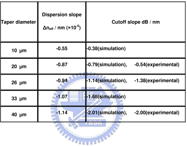
Table 3.1 The cutoff slopes and dispersion slopes for different waist diameters of taper filters immersed in Cargille index matching liquid.
Taper diameter Dispersion slope Δ ΔΔ Δneff / nm (××××10-5) Cutoff slope dB / nm 10 μμμμm -0.55 -0.38(simulation) 20 μμμμm -0.87 -0.79(simulation), -0.54(experimental) 26 μμμμm -0.94 -1.14(simulation), -1.38(experimental) 33 μμμμm -1.07 -1.68(simulation) 40 μμμμm -1.14 -2.01(simulation), -2.00(experimental)
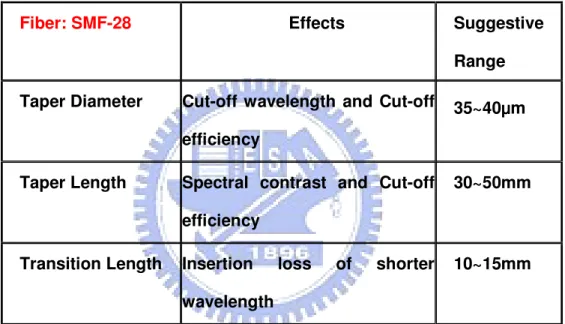
From the table 3.1, the optimal taper diameter is 40 µm for getting a high cut-off efficiency device. Therefore, we use experiments and simulation to investigate the optimal taper condition for SPF that has good performance. We summarize each effect of taper parameters and present suggestive range of taper parameters in table 3.2.
Table 3.2 Summary of each taper parameter
Fiber: SMF-28 Effects Suggestive
Range Taper Diameter Cut-off wavelength and Cut-off
efficiency
35~40μμμμm
Taper Length Spectral contrast and Cut-off efficiency
30~50mm
Transition Length Insertion loss of shorter wavelength
3.6 Reference
[3.1] R. P. Kenny, T. A. Birks, and K. P. Oakley, “Control of optical fiber taper shape,” Electron. Lett., vol. 27, pp. 1654-1656, 1991.
[3.2] T. A. Birks and Y. W. Li, “The shape of fiber tapers,” IEEE J. Lightwave Technol., vol 10, pp. 432-438, 1992
[3.3] The RSoft Photonics CAD Layout™ v5.1 User Guide
[3.4] BPM course slides, Devang Parekh, University of Berkeley, CA
[3.5] G. R. Hadley, “Transparent boundary condition for the beam propagation method”, Opt. Lett., vol. 16, pp. 624, 1991.
[3.6] G. R. Hadley, “Transparent boundary condition for the beam propagation method”, J. Quantum Electron, vol. 28, pp. 363, 1992.
Chapter 4
Wideband
tunable
short-pass double-cladding fiber filter
4.1 Introduction
Since the variation of propagation constant β(ω) can also substantially affect the propagation losses of lights through the mode cutoff effects, the dispersion engineering on β(ω) has been employed to achieve fundamental-mode cutoff LP01-C
SPF [4.1-4.6]. However, The cutoff slope can be increased by modifying waveguide dispersion [4.2-4.4] or by modifying the material dispersion [4.1,4.5-4.6] for silica-based S-band erbium-doped fiber amplifiers and lasers [4.1,4.3,4.7].
In this section, we propose a new structure of tapered fibers with a depressed-index outer ring that is made by double cladding fibers (DCLFs) surrounded by optical index matching liquids to achieve the sharpest LP01-C than ever reported. The material of
DCLFs( Fibercore:SMM900) has been introduced in section 1.3 that the depressed-index outer ring is Fu. The refractive index dispersion (RID) curves n(λ) of tapered DCLFs would be steeper and more λ-dependent than of tapered SMF-28 because of material dispersion characteristics. Therefore, we expect the depressed-index outer ring in tapered DCLF, usually F-doped with the thickness in the wavelength scale, can confine the shorter wavelengths more tightly than the longer wavelengths to produce a higher cutoff slope,
4.2 Experimental & simulation setup
The detailed fabrication procedure of tapered DCLFs SMM900 and measurement setup of filters that we apply Cargille index matching liquid as the new effective cladding for generating tunable LP01-c are the same as those of tapered fused SMF-28.
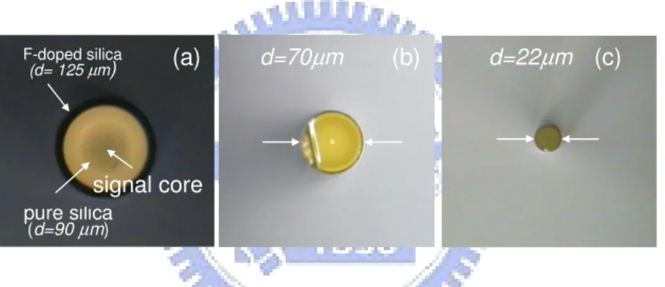
Fig4-1 shows the cross-sectional structures of the tapered SMM900 with diameter d equal to (a) 125, (b) 70, and (c) 22μm, respectively, examined under a 1000×CCD microscope. Through the tapering process, the F-doped outer cladding starts to affect RID n(λ) of DCLFs when the thickness of F-doped ring reduces down to the wavelength scale.
Fig 4-1 (Color online)Cross-sectional views of the SMM900 at different tapered diameters.
In our simulation, we design a double cladding structure as Fig4-2 and the other details are the same as the simulation for SMF-28. Since the Sellmeier coefficients of F-doped silica for SMM900 are not available, we consider approximately 1 mol% F-doped silica as the outer ring of SMM900.
d=70µm d=22µm signal core (b) F-doped silica (d= 125 µm) (a) (c) pure silica (d=90 µm)
.
Fig4-2 Sketch for double cladding fibers (DCLFs). The red part is core and blue part is inner cladding and yellow part (F-doped) is outer cladding.
4.3 Result & discussion 4.3-1 Experiment
Fig4-3 shows the transmission spectra of the tapered SMM900 SPF at different temperature and the taper diameter is 22 µm. It is obvious that the SPF can also be available for tapering DCLFs and the tuning range would cover all band (1250nm~1650nm). Fig 4.4 shows the transmission spectra of the tapered SMM900 SPF at different taper diameter d with taper length L0 is about 5 µm. When d goes
down to 10 µm, the cutoff slopes are getting flat since the waveguide has lost the confinement ability of short wavelengths, which is similar to the tapered SMF-28 SPF as stated before. However, when d is larger than 30 µm, the F-doped silica ring would confine the longer wavelength filed such that the evanescent field is not accessible. Therefore the maxima taper diameter of SMM900 is much smaller than of SMF-28 because of F-doped silica and it will be shown in the simulation section later.