行政院國家科學委員會補助專題研究計畫成果報告
※※※※※※※※※※※※※※※※※※※※※※※※※※
※
※
※
單晶片系統之接線分析與平面規劃之研究
※
※
Research on Interconnect Analysis and Floorplanning for SOC
※
※
※
※※※※※※※※※※※※※※※※※※※※※※※※※※
計畫類別:□個別型計畫
þ
整合型計畫
計畫編號:NSC90-2215-E002-009
執行期間:90 年 08 月 01 日至 91 年 07 月 31 日
計畫主持人:陳少傑
計畫參與人員:方志鵬、沈洪浩、戴志誠
本成果報告包括以下應繳交之附件:
□赴國外出差或研習心得報告一份
□赴大陸地區出差或研習心得報告一份
□出席國際學術會議心得報告及發表之論文各一份
□國際合作研究計畫國外研究報告書一份
執行單位:國立台灣大學電子工程研究所
中
華
民
國
九十一年
十月
十八日
1
百萬閘單晶片系統之設計方法論─子計畫一
單晶片系統之接線分析與平面規劃之研究
Resear ch on Inter connect Analysis and Floor planning for SOC
計畫編號:NSC90-2215-E002-009
執行期限:90 年 8 月 1 日至 91 年 7 月 31 日
主持人:陳少傑 台灣大學電子工程研究所
計畫參與人員:方志鵬、沈洪浩、戴志誠 台灣大學電子工程研究所
一、中文摘要
一般而言,要最佳化 IC 的性能必須盡 可能的減少連線延遲。而欲達成此目標的一 個最好方法莫過於在長的連線當中加入緩 衝器,從而使整體的延遲值降低。我們這個 研究針對多條線的繞線與緩衝器擺置的問 題作處理。我們的方法不同於以往的做法在 於:我們在一個步驟中同時解決繞線與緩衝 器擺置的問題,而並非將他們一分為二。我 們的方法將線的密集度、緩衝器的密集度以 及每條線的延遲值設為限制;而之前的研究 都只將其中之一或二作為限制。 為此我們開發出結合緩衝器擺置之全 域繞線器,並提出曼哈頓最短距離緩衝器插 入法、及以迷宮繞線法為基礎之緩衝器間繞 線法,其中曼哈頓最短距離緩衝器插入法的 處理速度相當快,甚至可以直接整合至平面 規劃的反覆式演算法,因而提高平面規劃解 的可繞性。 關鍵詞:晶片系統、平面規劃、緩衝器、全 域繞線器Abstr act
In general, optimizing IC performane needs to reduce the interconnect delay as much as possible. To achieve this goal, buffers are added in a long net to reduce its delay value. In this work, we try to solve the multi-net routing and buffer insertion problem by a new method. Instead of dividing the problem into different stages, our method
tries to route and insert buffers simultaneously. Our method also considers net congestion constraint, buffer congestion constraint and delay target of each net as our algorithm constraints, which have not been considered in all previous works. Thus, we have developed a global router combined with buffer-insertion for SoC design automation. The global router includes a Manhattan Routing (MR) algorithm and a Maze-based
Between-buffer Routing (MBR) algorithm,
where the processing speed of MR is quite
fast that it can be integrated into the iterative floorplanning algorithm to promote the routability of a floorplan solution.
二、緣由與目的
傳統上 IC 的自動化設計可以分為幾個 步驟:分割、平面佈置與針腳決定、擺置、 全域繞線、細部繞線、緊緻與驗證。這些步 驟彼此之間存有緊密的關聯,前步驟的好壞 常常影響後面步驟至鉅。我們的研究為全域 繞線的一環,因而以下大概對於各種全域繞 線的方法做簡述。 全域繞線大致上可以分為:迷宮繞線 法、直線搜尋法、流法及分層處理法幾種。 迷宮繞線是最早提出的方法,此法可以在路 徑存在的前提下找出一條最短路徑,其缺點 是繞一條線通常需要大量的計算時間。直線 搜尋法的精神在於設法從起點的方向,向著 終點的方向發射射線,如果遇到阻礙則轉 向,設法走到終點為止。直線搜尋法的缺點 在於不保證能找出最短路徑的繞線。流法則 是設法將原問題轉化為一個由線段及端點2 所形成的圖,在此圖上求解的一個方法。而 分層處理法則是設法將原問題以分割處理 再合併的方法做處理。 現代化的繞線中,為了控制延遲值在一 定的範圍內,緩衝器擺置是不可避免的。而 繞線與緩衝器的擺置又通常是彼此互相影 響的步驟。之前處理此問題的方法大致上可 以分為緩衝區塊法 (Buffer Block)[1-4] 與 緩衝區位(Buffer Site) [5] 法兩種。緩衝區塊 法是先決定何地設定為專門擺置緩衝器之 區塊,俟區塊決定之後,在設法繞線,如必 須加緩衝器則必須將線繞至某區塊之中,加 一緩衝器,再將線繞出去。緩衝區位法則是 將原擺置好的平面分割為若干個小方塊,每 個小方塊中都有其可繞線與緩衝器可擺置 的上限值;在該方塊所繞之總線數及所擺之 總緩衝器數不得超出相對應的上限值。接下 來緩衝區位法先進行繞線,等所有線都繞好 之後,再進行緩衝器擺置的步驟。這兩種方 法本質上都將繞線與緩衝器擺置分為兩個 步驟處理。但因為這兩個步驟實際上有很深 的牽扯,所以採用任一種方法常常都需要做 很多次的遞迴才能得到一個還算可行的解。
三、研究方法
有很多文獻的內容是針對繞線與緩衝 器擺置的處理,如 Zhou [6]、Cong [1]、Sarkar [2]及 Alpert [5]的研究。Sham [7]所提出的 線密度預估法是奠基於機率的法則 [8]。在 此報告中,我們結合了 Sarkar 的 IFR 公式、 Alpert 的 Buffer Site 假設、Sham 的線密度 預測法,並加入我們所設計的種種方案而形 成我們的解。 我 們 的 預 測 線 密 度 方 法 主 要 是 採 用 Sham 法的精神。不過我們對他們的基本精 神作了修正。我們將預測階段視為與實際繞 線徹底切分。在預測階段使用純邏輯的考 量,不考慮所有的障礙物可能的影響。如此 可以大大加快預測的速度,並且在邏輯上這 樣做較有一致性。 預測緩衝器的密度的方法比起線密度 來得麻煩許多。我們採用的方式是對所有可 能繞線的結果視為等價(機率相同),在這個 基礎上分別去考慮對每種繞線結果加入不 同個數的緩衝器的機率。對所有的線都做這 件事之後疊加就得出最後的緩衝器密度場。 根據線限制場、緩衝器限制場、線密度 場及緩衝器密度場四個場我們可以得出線 成本場及緩衝器成本場。這兩個場將指導我 們的繞線緩衝擺置器去找出最小成本的繞 線及緩衝器擺置法。 我們提出了兩個處理繞線—緩衝器擺 置 的 演 算 法 : 曼 哈 頓 繞 線 法 (Manhattan Router, MR) 與 緩 衝 器 之 間 迷 宮 繞 線 法 (Maze-based Between-Buffer Router)。曼哈 頓繞線法(MR)是基於動態程式法的演算法 (參見 Fig. 1);此法可以很快的在曼哈頓盒 子 內 找出 最 小成 本 的 線 路徑與緩衝器位 置,而所繞的線長等於最短曼哈頓距離的長 度。我們將此演算法設定為主要的繞線法; 實驗證實大約有 95%的線是由此法所繞。Given: two end points S and T; n buffer sets {B1,1,
B1,2, … , B1,m1}, {B2,1, B2,2, … , B2,m2}… ,
{Bn,1, Bn,2, … , Bn ,mn}.
Goal : choose a path from S to T, which resides within the Manhattan Box with no detour. The path will intersect each buffer set with one element, choose this element as the buffer site. Fig. 1 Algorithm MR 緩衝器之間迷宮繞線法(MBR)是基於 迷宮繞線法(參見 Fig. 2),試圖在兩個可能 的緩衝器位置之間找出最短路徑的方法。如 果路徑存在,此法可以保證找出一條最短路 徑。此法的缺點在於運算量很大,因而速度 很慢;我們將此方法設定為在曼哈頓繞線做 完之後的後續處理,專門針對那些在曼哈頓 Algor ithm MR 1. For (i = 1 to n) Do
2. Using previous stored min-cost path (if any), find min-cost path from S to all elements of ith buffer set {SBi,1,
SBi,2, … , SBi,mi} and store them.
3. Find min-cost paths of {Bn,1T, Bn,2T, … ,
Bn,mT}
4. Combine {S Bn,1, S Bn,2, … , SBn,m1} and { Bn,1T, Bn,2T, … , Bn,mnT }, find min-cost path from S to T.
3
繞線法失敗的線去繞。結合這兩個演算法即 為我們的繞線—緩衝器擺置法。
Given: Two end points S and T; a buffer set B =
{B1, B2, … , Bn}.
Goal : Choose a min-cost path from S to T, which going through a subset of B, and which total delay value does not violate any delay budget. Fig 2 Algorithm MBR
四、結果與討論
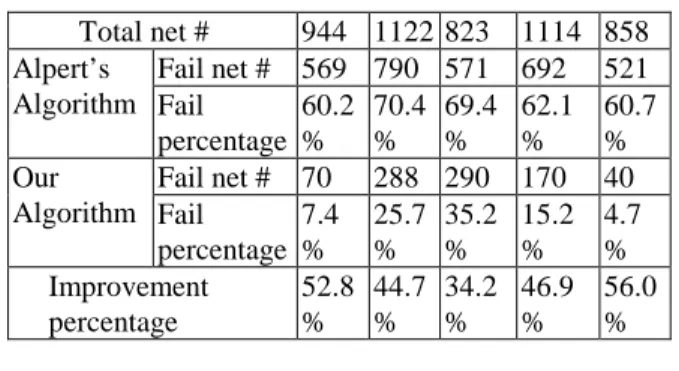
我們的方法最大優點在於可以將繞線 及緩衝器擺置在同一步驟之內解決。而所有 之前的方法均將這兩者切割為兩個步驟。這 兩者互相影響的程度太大,因而任何切割的 演算法均會導致大量遞迴尚且找不到好的 解的問題。我們的演算法徹底的解決了這樣 的問題。 如表一所示,我們的演算法在可繞度上比 起其他的演算法高出許多。五、計畫成果自評
實驗證實我們所提的方法比起之前所 有的方法來得更好。我們的演算法亦可輕易 的與平面擺置或是細部繞線的步驟結合而 產生一個完整的 IC 自動化設計工具。這工 具將可用於現代化的 IC 設計,尤其是 SOC 設計領域中。Table 1 Comparisons of Alpert’s and Our Algorithm Benchmark # 1 2 3 4 5 Total net # 944 1122 823 1114 858 Fail net # 569 790 571 692 521 Alpert’s Algorithm Fail percentage 60.2 % 70.4 % 69.4 % 62.1 % 60.7 % Fail net # 70 288 290 170 40 Our Algorithm Fail percentage 7.4 % 25.7 % 35.2 % 15.2 % 4.7 % Improvement percentage 52.8 % 44.7 % 34.2 % 46.9 % 56.0 %
六、參考文獻
[1] J. Cong, T. Kong, and D. Z. Pan, “Buffer block planning for interconnect-driven floorplanning”. Proc. IEEE/ACM Int. Conf. Computer-Aided Design, pp. 385-363, 1999.
[2] P. Sarkar, V. Sundararaman, and C.-K. Koh, “Routability-driven repeater block planning for interconnect-centric floorplanning”. Intl. Symp. Physical Design, pp. 186-191, 2000. [3] F. F. Dragan, A. B. Kahng, I. I. Mandoiu, S.
Muddu, and A. Zelikovsky, “Provably good global buffering using an available buffer block plan”. Proc. ICCAD, pp. 104-109, 2000.
[4] F. F. Dragan, A. B. Kahng, I. I. Mandoiu, S. Muddu, and A. Zelikovsky, “Provably good global buffering by multiterminal multicommodity flow approximation”. Proc. ASP-DAC, pp. 120-125, 2001..
[5] C. Alpert, J. Hu, S. Sapatnekar, and P. Villarrubia, “A practical methodology for early buffer and wire resource allocation”.
Proc. DAC, pp. 189-194, 2001.
[6] H. Zhou, D. F. Wong, I. M. Liu, and A. Aziz, “Simultaneous routing and buffer insertion with restrictions on buffer locations”.Proc. DAC, pp. 96-99, 1999. [7] C. W. Sham, W. C. Wong and Evangeline F.
Y. Young, “Congestion estimation with buffer planning in floorplan design”. Intl. Symp. Physical Design, 2002.
[8] J. Lou, S. Thakur, S. Krishnamoorthy, and H. S. Sheng, “Estimating routing congestion using probabilistic analysis”. IEEE Trans. CAD of ICS., vol. 21, No.1, pp. 32-41, Jan. 2002.
Algor ithm MBR
1. Use MR to route a path from S to all possible buffer sites, then store the route and delay value.
2. While (not all buffer sites are chosen as a new source) do
3. new source ← pick-up an unchosen min. delay buffer site
4. Use MR to route a path from the new source to all un-chosen buffer sites, then update routing path and delay if necessary. 5. Using MR to route a path from each buffer
site to T, choose a path with minimum cost and delay value which fits the delay budget as the final routing path.