Accelerated Authentication Utilizing Refined Neighbor Graph for
Handoff in WLAN
使用改良式相臨圖之無線區域網路漫遊快速認證
Abstract
WLAN has grown in popularity recently according to the characteristics of wireless access and mobility. Voice applications on WLAN usually require to access network resource un-interruptedly. To keep high quality of communication for mobile users employing these applications, WLAN system must provide the ability of fast handoff across different AP. However, the WPA authentication requires much time such that WLAN is difficult to support the fast handoff. In this paper, we propose a secure accelerated authentication scheme based on refined neighbor graph. Through key pre-agreement between each STA and neighbor APs in advance and the reduction of handover authentication process, our protocol can reduce greatly authentication latency of handoff. Moreover, a refined neighbor graph can only selects the certain of APs that STA most likely roams into further to anticipate in key pre-generation. Consequently, our scheme can minimize efficiently network traffic load that results from key pre-agreement while providing the fast authentication of handoff.
由於具有無線存取及可移動的特性,無 線區域網路近年來已被廣泛地建置於各場 所,語音相關應用通常需要穩定順暢的播 放能力,為了提供用戶一個較佳的通訊品 質,無線區域網路必須支援無縫隙漫遊功 能。然而,過長的WPA認證時間使它難 以達成這項目標。本篇論文提出使用改良 式相鄰圖的快速安全認證方法來縮短認證 延遲,透過行動工作站與相鄰無線接取器 間預先交換金鑰資訊產生密鑰的方式,並 予以簡化 Handoff 認證程序,本協定可以 有效縮減使用者跨無線接取器漫遊時重新 認證的時間。此外,改良式相鄰圖可以適 當地決定哪些無線接取器應事先與行動工 作 站 協 議 產 生 認 證 金 鑰 , 不 以 相 鄰 圖 (Neighbor Graph)上所有相鄰無線接取器 為協議標的,此方法僅選擇該使用者下次 漫遊機率較高的數個無線接取器作為與行 動工作站進行前置溝通的對象。因此,認 證協定在維持一定認證效率的水準同時, 仍可減少不必要的網路通訊負載。
Keywords: WLAN, STA, AP, authentication,
Refined Neighbor Graph
關鍵詞:無線區域網路,行動工作站,存取
Tsai-Te Liao Department of Computer Science National Tsing Hua
University, Hsinchu, 300 Taiwan, R.O.C [email protected] Chiung-Hsun Chen
Department of Computer Science National Tsing Hua
University, Hsinchu, 300 Taiwan, R.O.C mikemouse @is.cs.nthu.edu.tw
Cheng-Kai Chen Networks & Multimedia
Institute, Institute for Information Industry,
Taiwan, R.O.C [email protected] Hung-Min Sun
Department of Computer Science National Tsing Hua University, Hsinchu,
300 Taiwan, R.O.C [email protected]
點,認證,改良式相臨圖
Ⅰ. Introduction
Due to the characteristics of mobility, and high bandwidth, WLAN 802.11 [4] has become more and more popular. Many Internet service providers employ hotspots in public areas such as airport, conference center, coffee shop. Mobile station (STA) can access internet through an AP. To ensure that only legitimate users can access network resources and any attacker can not disguise as an AP, mutual authentication should be performed between each STA and each AP when each STA wants to access the wireless LAN.
We briefly introduce the 802.11i protocol [5] . Wired Equivalent Privacy (WEP) is original security mechanism to provide protection in WLAN. But weak security protocol and ciphersuite make it vulnerable to several kinds of attacks from malicious user. In order to overcome the drawback of WEP, 802.11i is ratified to supersede the previous security specification. 802.11i provides a number of new security features. Those features include enhanced authentication mechanisms for STA, key management algorithms and enhanced data encrypt/decrypt mechanism, called CTR with CBC-MAC Protocol (CCMP), and, Temporal Key Integrity Protocol (TKIP).
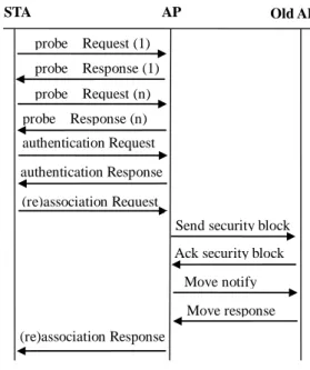
A robust security network association (RSNA) establishment procedure for IEEE 802.11 can be divided into four phases – search, association, IEEE 802.1X authentication [2] and 4-way handshake. Before connecting to wireless LAN, each STA first discovers available APs by passive probe or active probe. When STA performs active probe, the AP received the Probe Request frame sent by a STA will reply Probe Response frame to the STA. The Probe Response carries a new information element named RSNIE that is included to advertise cipher algorithm and
authentication method supported by device. The RSNIE contains authentication and pairwise cipher suite, a single group cipher, RSN Capabilities field and PMKID list
which can identify PMK. The detail
transmission is shown in Figure 1.
After an AP is selected by a STA, authentication and association operations are performed between the STA and the AP. The IEEE 802.11 specifies two authentication algorithms called open system and share key authentication that is superseded by IEEE 802.11i due to flaws of security. To keep backward compatibility, the open system authentication is invoked as usual. If STA reassociate to new AP and IAPP [3] is enabled, the new AP submits send-security-block to old AP which verifies the security block by using secret shared with AAA server and responds with ACK-Security-Block. Cipher key in security block can be used by new AP to encrypt move notify message at this time. The new AP transmits move notify message to old AP to request context information of STA. Then the old AP sends move response to new AP. Finally the new AP replies association to STA. probe Request (1) probe Response (1) authentication Request authentication Response (re)association Request (re)association Response
Send security block Ack security block
Move notify Move response probe Request (n)
probe Response (n)
STA AP Old AP
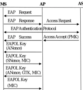
In third phase, the AP delivers directly EAP-request message to STA to perform mutual authentication for STA and AAA server. The master key (MK) and pairwise master key (PMK) are generated through exchange of information between STA and AAA server. The MK is derived from EAP authentication protocol, while PMK may is generated from MK. Upon the completion of 802.1X, EAP success indication followed by encrypted PMK will be transported from AAA server to AP. The detail transmission is shown in Figure 2
In the final phase, the AP and STA use PMK to obtain and verify pairwise transient key (PTK). Meanwhile, the cipher suites are negotiated via 4-way handshake and GTK for broadcasting message is delivered to STA.
When wireless LAN utilizes the protocol of IEEE 802.11i, the network system can resist malicious attackers. Nevertheless, IEEE 802.11i will introduce a large mount of authentication delay. Therefore, to provide uninterrupted service in WLAN is difficulty. To provide uninterrupted service is essential for Voice phone and multimedia applications system. The entire latency of handover must be smaller than 50 ms to prevent connection jitter in Voice IP application [6] . Unfortunately, the full authentication time of 802.11i exceeds 140
ms. Therefore, many researches [8] [12] [15] make much effort on how to shorten the latency of handoff. And Proactive-key distribution [8] can provide lower authentication latency which is 48 ms. Besides, Mishra’s [10] presents that probe latency is from 37 to 400 milliseconds and provides more than 90% latency of overall connection process in IEEE 802.11. Several literals are proposed to aim at reducing probe delay [10] [11] [13] . Shin’s scheme [13] has the lowest probe latency which is 31 ms. Even if both Shin’s probe scheme and proactive key authentication are adapted simultaneously; the delay of handoff still can not be accepted in voice and multimedia applications. Thus, the authentication time for handoff in WLAN should be diminished as far as possible. Therefore, we propose an efficient scheme to reduce the latency of handoff.
This paper is organized as follows. Section II is related work about authentication protocol and mobility prediction scheme. Section III presents refined neighbor APs selection scheme. Section IV introduces the proposed efficient authentication protocol. Section Ⅴ presents security analysis of the proposed authentication protocol. Section Ⅵ describes experiment environment and result. Section Ⅶ is conclusion.
Ⅱ. Related Work
In order to achieve the efficient handoff, Pack has proposed predictive authentication be performed to neighbor APs [15] . The scheme introduces the frequent handoff region (FHR) that is a subset of adjacent APs. The FHR is determined from N×N matrix (N means number of AP in wireless LAN). After completion of authentication between STA and AAA server, AAA server sends multiple authentication response to all APs within a FHR. Although predictive authentication can improve handoff performance by utilizing FHR, there are some shortcomings as follows. Firstly, by
EAPOL Key (MIC) EAPOL Key (ANonce, GTK, MIC) EAPOL Key (SNonce, MIC) EAPOL Key (ANonce) AP AS EAP Request EAP Response
EAP Authentication Protocol
Access Request
Access Accept (PMK) EAP Success
MS
using FHR to represent neighbor APs, it
imposes O(n2) computations and space
complexity. Secondly, matrix structure is inappropriate for dynamic topology of network. Finally, server may require large mount of space to record all handoff events.
Moreover, Arunesh [8] proposed proactive key distribution that intends to reduce the latency of authentication. The protocol is based on neighbor graph which is maintained in AAA server. The neighbor graph is undirected graph G = (V, E) in which V = {ap1, ap2, …, apn} is the set of all
APs and edge e = (api, apj) between api and
apj. The edge of two nodes is created on
receipt of reassociation request by new AP. As STA and authentication server have authenticated mutually to each other, PMK is sent to the associated AP from server. Afterward, the server generates the next PMK and sends NOTIFY-REQUEST message to each neighbor through. An AP received NOTIFY-REQUEST may decide to request PMK from AAA server or not. If the AP requires the PMK, it sends NOTIFY-ACCEPT. If not, it delivers NOTIFY-REJECT to AAA server. On receiving NOTIFY-ACCEPT message, the AAA server responses with ACCESS-ACCEPT message with next PMK. Once STA roams to new AP, STA derives PMK using the same way as server did. The STA and AP then negotiate new PTK and authenticate each other via 4-way handshake. If AP does not have PMK, a full authentication must be carried out. The proactive key distribution protocol can shorten authentication delay to 48 ms. The disadvantage of the protocol is that it burdens the AAA server and leads to large traffic over network by informing all neighbor APs of the PMK. Moreover, the protocol needs to add three new RAIDUS message for transmitting proactive key to neighbor APs. Although the protocol can reduce effectively authentication latency, the total handoff latency with proactive key schema still exceeds 50 milliseconds.
To eliminate unnecessary message exchange between APs, Pack has presented
a selective neighbor cache scheme [14] . In the scheme, each AP maintains individually neighbor graph via reassociation request from STA and move notify packet from adjacent AP. The AP sends the STA’s context to its neighbor APs whose handoff probabilities are equal to or higher than a predefined threshold value. Though the SNC scheme has a lower cache hit probability than proactive neighbor scheme that pass mobile context to all neighbors, but the difference decreases when time proceeds. The scheme can reduce signal cost by 30-40% with causing to diminish lightly cache hit rate only. However, the selective neighbor cache is learnt by mobility information of all STA. Even one STA never visits a particular AP, pre-distribution of user context to the particular AP will still take place if other STAs frequently roam to the AP from current AP. Obviously, this scheme would result in significant traffic over network as the number of users increase progressively. In addition the neighbor graph is created as undirected graph whose edge is added once STA move to or move from neighbor AP. In fact, user may often
handover to AP2 from AP1 but never
handover to AP1 from AP2. Therefore, it is
improper for selective neighbor graph to be used unchangeably to predict user mobility.
Mukherjee proposed Dual State Transition Predictability Algorithm (DSTPA) [16] to minimize the network overhead incurred from pre-authentication, while maintaining authentication time to around 50-70ms. The DSTPA pre-distributions PMKs according to the previous movement pattern of each MS and continuously updates a frequency matrix after every handoff of the MS. This scheme combines the conception of order 2 model [7] and mobility prediction of per user. When an MS first contacts the WLAN, the DSTPA performs a full EAP-TLS authentication with the AAA server. Each time an MS roams from APj to APk if the previous AP
was APi, a matrix is updated in the form
<APi APj APk> to reflect the frequencies of
matrix would be searched by the AAA server to find out the non-zero frequencies of APk such that the form < APi APj APk>
had occurred. The first C numbers of APs which have higher frequencies of the corresponding handoff are provided with the PMK by the AAA. Here C is a parameter which determines the class of service of the MS.
Ⅲ. Refined Neighbor Graph
The refined neighbor graph (RNG) is based on neighbor graph proposed by Arunesh.[9] . The scheme provides three characteristics. Firstly, RNG is created for each user. Since each user has different movement path and network access time, the individual movement pattern will help to predict more precisely the next AP. Secondly, RNG is directed graph. A user may often roam from AP1 to AP2 but rarely roam from
AP2 to AP1, so directed graph is fit to
determine the visited APs at next time. Finally, unlike the neighbor graph selects all APs that users ever roamed from the associated AP, RNG only selects some APs with higher handoff probability that a user ever roamed from the associated AP.
RNG is a weighted digraph G=(V, E) where V={ap1,ap2, …,apn} is a set of all APs
and E={e1,e2,…,en} is set of all edge. Each
edge <api, apj> means that api and apj have a
handoff relationship. The handoff relationship exists when a user ever handoff from one AP to another AP. The weighted on edge <api, apj> indicates the probability that
a user handoffs from api to apj. As Figure 3
illustrates, the RNG is created from the the topology of WLAN shown in the left side of Figure 3. Since motion paths of a user from AP1 to AP2 and motion paths of the user
from AP1 to AP2 appear in topology of
WLAN, the edge <ap1, ap2> and <ap2, ap1>
meet handoff relationship. Therefore, the two directed edge exists in RNG. The weight value on edge <ap2,ap1> indicates the
handoff probability that a user will roam to ap1 is 0.4, when the user has connected
currently to ap2.
Since RNG selects many specific neighbor APs according to individual movement history of each user, it is almost impossible for any AP to record the movement pattern of all users that ever visited to the AP. Thus, we can utilize the AAA server to maintain the movement pattern of all users or allow STA to keep movement pattern itself. Regardless of the AAA server or STA is responsible for determining neighbor APs, it needs to store movement data shown in Table 1. The movement table only keeps information of one hop in motion path. The User field is the identification of a user that can appear as user account or user code. The AP field represents the target AP that is treated as the source of motion path. The NextAP field stores the next handoff AP that is the destination of motion path. If a user disconnects with any AP, the content of the Next AP field will be the same as that of the AP field (see first record in Table 1). The Time field is the number of time slot when a user moves from AP in AP field to AP in NextAP field. We divide whole time into
ap1 ap1 ap5 ap3 ap4 ap2 ap2 ap3 ap4 ap5 AP
Motion path of STA
0.2
0.1 0.05 0.4
Figure 3 – the topology of WLAN and RNG
User AP Next AP Time Count
uid1 AP1 AP1 2 17
uid1 AP2 AP1 10 40
uid1 AP2 AP2 21 25
uid1 AP2 AP3 5 20
uid1 AP2 AP4 1 10
many time periods that may be one day or one week and separate each time period into several time slots. Two time slots that belong to different time period and have the same slot order are regarded as the same. The proposed scheme uses handoff number in designated time slots to decide the neighbor APs, it is unnecessary to know the precise time when handoff event occurs. To minimize the record number of movement data, the scheme only saves the time slot rather than real time. The count is the number that a user handoff from AP in AP field to AP in NextAP field during one given time slot
Each time STA contacts AP successfully, RNG scheme will be invoked. This scheme first finds out the time span which current time slot belongs to. The time span is comprised of all time slots initially. RNG then calculates the number of handoff from associated AP to all next APs in movement history database and computes the handoff probability to each next AP during current time span. It sorts these handoff probabilities in decreasing order. The scheme selects APs that have higher handoff probability as neighbor APs until the accumulated probability is more than handoff probability threshold. Then, the scheme will update the corresponding handoff number in movement history database when STA handoffs from other AP to current associated AP. If the current time span can be separated further, and if both the handoff numbers of first part in time span that is according to the location of the half amount of handoff and the handoff numbers of second part in time span are more than the half of the threshold of handoff number predefined, the time span then is divided into two time span. The threshold of roaming probability is dynamic and depends on the service level of the user. As a user owns high priority or needs un-interrupted connection, the threshold of handoff probability should be set to higher value. Otherwise, the threshold of handoff probability can be lower. RNG algorithm is shown as follows:
Algorithm 1 neighbor AP selection for RNG 1 APj is current associated AP
2 Tm is time slot when association occurs 3 PT is the hit probability threshold 4 HNT is the threshold of handoff number 5 if (user visits APj first time)
6 initiate time span TSi to all time slot
7 endif
8 find time span TSi which Tm belongs to
9 Compute the number of handoff from APj to all next AP during TSi
10 for (each next APk of APj)
11 Compute the number of handoff from APj to APk during TSi
12 Compute handoff probability Pjk to next
APk during TSi
13 end
14 Sort non zero Pjk in decreasing order
15 prob ← 0
16 for (each Pjk generated in line 15)
17 if (prob < PT) then
18 select APk as neighbor AP 19 prob ← prob + Pjk
20 endif 21 end
22 update the number of handoff from upstream APi to APj during TSi
23 if (TSi contains more than one time slot)
then
24 if (the amount of handoff numbers in TSi
more than HNT) then
25 according to the location of the half amount of handoff, to separate TSi
into two subsets.
26 If (any one subset contains the amount of handoff which is larger than the half of HNT) then 27 TSi is divided in to subset as TSi-1
and TSi-2.
28 endif 29 endif 30 endif
Ⅳ. Accelerated Authentication
proposed protocol is defined as follows:
AP_MAC : The MAC address of access point STA_MAC : The MAC address of mobile station ANonce : The nonce derived from access point SNonce : The nonce derived from mobile station ACi : Indication whether mobile station has PMK relative to APi
SC_List : The message that includes the MAC address of each neighbor and cache indication of STA for corresponding AP .
AP_MAC1||AC1||AP_MAC2||AC2…
AToken_List : The message that include nonce, MAC address, and cache indication of neighbor APs. ANonce1||AP_MAC1||AC1||ANonce2||AP_MAC2||A C2…
PMKn : PMK for next handover
KC: The usage count of current PTK for authentication
This section describes the proposed authentication protocol when 802.1X AS participates in mutual authentication. Remote Authentication Dial in User Service (RADIUS) protocol [1] is used for communication between AP and authentication server. The protocol bases on RNG scheme implemented on STA.
Connection Procedure
When user first connects to wireless LAN, the flow of the proposed protocol can be divided into two parts: (1) RSNA establishment. (2) Key pre-agreement. The first part of the proposed protocol is the same as RSNA establishment originated from IEEE 802.11i. Therefore our description focuses on the second part.
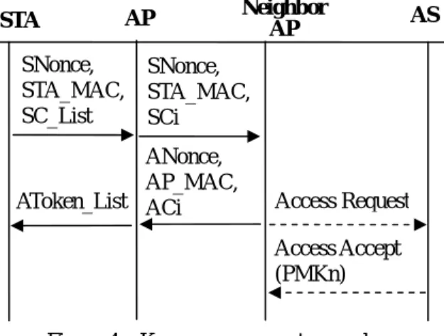
We utilize Figure 4 to express the key pre-agreement. Firstly, we add a new type of Descriptor type in EAPOL key frame to
inform receiver of the key information. And each STA utilizes the EAPOL key frame adopted in 4-way handshake to transmit some information. The information includes a nonce derived from STA, MAC address of STA, and a list which contain address of each neighbor AP and cache indication that indicate if STA share PMK with the corresponding AP.
Secondly, upon the receipt of the key information sent from STA, the associated AP creates Cache-Notify packet for each neighbor AP. Each Cache-Notify packet comprises a nonce generated by STA, MAC address of STA and cache indication of a relative neighbor AP.
Thirdly, after receiving Cache-Notify packet from the associated AP, a neighbor AP needs to generate a random number as Anonce. Then it replies Cache-Response packet to the associated AP. The Cache-Response packet contains an Anonce selected by the neighbor AP, MAC address of the neighbor AP, and cache notification to indicate whether the AP will use old PMK in cache or new PMK sent from AAA server. To achieve our goal, two data fields are appended into cache response. One is Context Block is variable length field and stores the information. The other is Context Length to indicate the number of octets of the Context Block.
According to the cache indication of Cache-Notify packet, there are three cases as follows.
1. Both STA and the AP have PMK cache, this AP sets cache indication to true. 2. When the AP does not have PMK
cache, the AP sets cache indication to false. And it delivers an access request with the MAC of the STA to AAA server to ask the PMK relative to STA. 3. When STA has no PMK cache and
neighbor AP has corresponding cache for the STA, the AP deletes the corresponding PMK cache and sets cache indication to false. Then it sends an access request with MAC address of STA to AAA server to ask the PMK AS SNonce, STA_MAC, SC_List STA AP Access Request Access Accept (PMKn) SNonce, STA_MAC, SCi ANonce, AP_MAC, ACi AToken_List Neighbor AP
relative to STA.
Subsequently, the neighbor AP initiates the key counter of the STA to 0 in order to synchronize with the STA and caches the PTK that is derived from nonce and PMK.
Once authentication server receives Access Request from AP, authentication server will deliver new PMK within Access Accept to the neighbor AP that requests new PMK. The derivation of PMK key is shown in (1).
PMKn=PRF(MK, SeqNo||AP_MAC||STA_MAC) (1)
SeqNo is sequence number maintained by AAA server and STA. By applying the sequence number to pseudo random function, we can ensure that the PMK is unique. Although RADIUS does not define any attribute that allows AP to request the AAA server to submit next PMK, we utilize Vendor-Specific attribute included in Access Request to inform server of PMK requirement from AP. Through the new subtype in Vendor-Specific attribute, the authentication server can have the knowledge of that any AP needs new PMK. In regard to Access Accept, its format can be the same as the Access Accept used in 802.1X authentication. In this step, it generates PMK by using master key and sequence number. Finally server replies Access Accept with PMK to neighbor AP.
Fourthly, until receiving all Cache-Responses packets from each neighbor AP, the associating AP combines nonce, MAC address of each neighbor AP and cache indication into a token list. It utilizes the EAPOL key frame to transmit the token list to the STA.
Fifthly, After the STA receives the token list packet from the associated AP, it retrieves each Anonce and cache indication from the token list. Then the STA takes various actions according to PMK cache and cache indication shown as follows.
1. If the STA has PMK shared with a neighbor AP and cache indication of the neighbor AP is true, the STA generates PTK key based on the PMK.
2. When the STA has PMK shared with a neighbor and cache indication of the neighbor is false, the STA must delete the PMK and generate new PMK. Finally, PTK is derived from the new PMK.
3. If the STA has no PMK shared with a neighbor, it generates new PMK and calculates PTK by using the PMK. Finally, STA initiates key counters corresponding to each neighbor AP to 0.
Handoff Procedure
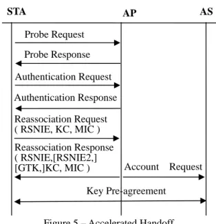
As a STA moves away from current associated AP, the STA commences performing handover procedure. The handover procedure contains four steps: (1) access point scan. (2) open system authentication. (3) reassociation establishment. (4) key pre-agreement. (Figure 5)
The first two steps are the same as the as RSNA establishment originated from IEEE 802.11i. The STA will initiate reassociation with target AP on the accomplishment of open system authentication. To carry authentication message, we make the slight modification to Reassociation Request packet. We add new authentication information element (IE) in frame body of Reassociation Request. The new IE contains element ID, KC, and MIC. The element ID of authentication IE can be assigned from
Reassociation Request ( RSNIE, KC, MIC ) Reassociation Response ( RSNIE,[RSNIE2,] [GTK,]KC, MIC ) STA Account Request Authentication Request Authentication Response Probe Request Probe Response AS AP Key Pre-agreement
the reserved values specified in IEEE 802.11 standard. The KC value within Reassociation Request is equal to the key counter maintained by STA. The MIC is calculated over the frame body of the Reassociation Request with MIC field set to 0 by using KCK key.
There are three situations. Firstly, if a STA does not possess relative PMK shared with target AP, it should send Reassociation Request without Authentication IE and PMKID to target AP, and the AP must initiate full authentication. Secondly, if a STA has PMK relative to target AP and does not hold relative PTK due to no key pre-agreement between AP and STA in advance, it should send Reassociation Request with PMKID of this PMK involved in RSNIE to target AP, and the AP must initiate authentication (only includes 4-way handshake). Finally, a STA computes MIC using KCK and sends Reassocation Request that contains KC and MIC to target AP.
Upon the receipt of Reassociation Request frame from STA, an AP will authenticate the STA and reply with Reassociation Response. The AP can take different action according to the following three situations:
(1) When an AP receives Reassociation Request without authentication IE, it replies Reassociation Request to STA. If Reassociation Request contains PMKID and the AP has corresponding PMK, only 4-way handshake is performed after the AP replies Reassociation Request to STA. Otherwise, full authentication will be invoked.
(2) When the AP shares the same PMK with the STA, the AP first checks KC in the Reassociation Request. If KC is smaller than local key counter which is stored in the AP, the Reassociation Request is silently discarded. Otherwise, AP continues to authenticate user by validating the MIC. If the MIC is invalid, the AP directly discards the Reassociation Request frame. After current AP determinates that user is
legitimate, the AP replies with Reassociation Response with MIC to STA. The AP must wait for a timeout period after sending Reassociation Response to STA. If the associated AP does not receive a repeat of Reassociation Request or Disassociation frame from the STA during the timeout period, it installs key into IEEE802.11 MAC. Subsequently, the AP increases local key counter by one and sends Accounting Request to AAA server. After receiving Accounting Request, the AAA server is also responsible for increasing sequence number shared with the STA by 1. If the AP receives Disassociation frame before timeout expires, it delivers Disassociation frame to STA and waits for one timeout that is used to receive possible repeat of Disassociation frame from STA.
(3) If the AP has not cached the relative PMK, it will ask AAA server the relative PMK. Since there is no common PTK between STA and the AP, the AP should inform the STA that 4-way handshake will be performed. To this end, a new code in status code field of Reassociation Response is created. To protect Reassociation Response, we create one new information elements called verification IE that contains two random numbers and MIC. This MIC that is calculated over frame body of Reassociation Response using temporal KCK. These random numbers are used as the material of temporal PTK generated from PMK. The AP first asks AAA server for relative PMK which is computed using current sequence number. After receiving response from AAA server, the AP generates two random numbers that are included in Reassociation Response and calculates PTK by using the PMK with nonce set to these two random numbers. Then it replies Reassociation Response in which MIC is derived from KCK within temporal PTK. Finally, the AP performs 4-way handshake to derive the PTK key
by sending EAPOL key frame to STA. As 4-way handshake has accomplished, the associated AP initiates local key counter to 1.
On receiving Reassociation Response sent from target AP, the STA will authenticate the AP or adopt new mutual authentication according to the following three situations:
(1) When a STA receives Reassociation
Response without authentication IE, the STA waits for full authentication initiated by associated AP.
(2) When RSNIE and Authentication IE are involved in Reassociation Response, the STA can authenticate target AP. The STA first begins to check KC and MIC value after receiving Reassociation Response sent from target AP. If KC is smaller than key counter kept in STA or MIC is invalid, the STA silently discards the frame. In the situation, STA may ignore connection to WLAN after repeating transmission of reassociation response a several number of times. If both KC and MIC are valid, the STA continues to check RSNIE. When the STA finds out that RSNIE in the response is different from RSNIE AP announced in Beacon frame or in Probe Response frame, it must disconnect to the network and tries another reassociation. If second RSINE appears in the Reassociation Response frame and the STA rejects to accept cipher suite specified in the RSNIE, the STA sends Disassociation frame to target AP. The STA retries to transmit disassociation frame to target AP if it does not receive Disassociation frame from target AP when disassociation timeout expires. If there is no second RSNIE or STA accepts cipher suite specified in the frame, STA can install PTK and install group key (GTK) if GTK is in the Reassociation Response. Then the STA increases local key counter by 1 and increases sequence number shared with AAA server by 1.
(3) When status code of 4-way handshake requirement appears in Reassociation
Response, the STA derives temporal PTK from PMK with nonce set to the random number in verification IE of the response frame and verifies MIC that is calculated over the frame body using KCK within the temporal PTK. If the MIC is invalid, the Reassociation Response is discarded silently. If the MIC is valid, the STA clears PTK cache and waits for 4-way handshake initiated by the associated AP. Once 4-way handshake complete successfully, the STA sets local key counter to 1.
After the reassociation between STA and AP has been done, the STA has the right to access wireless network resources. Afterward, the key pre-agreement that is the same as that of full authentication must be further performed.
Ⅴ. Security Analysis
. Masquerade threat -
Under the condition that key hash function is enough strong, any attacker can not compute MIC unless the key has been learned. Any one except STA, AP, and AAA server does not have the knowledge of PTK. Thus an adversary is not able to forge Reassociation Request with correct MIC to authenticate to AP. That is, any one can not masquerade STA. Likewise, an attacker is not capable of masquerading AP since MIC within Reassociation Response can not be computed without PTK.
. Replay threat –
The protocol applies key counter to protect against replay attacker during handover period. The key counter is initiated to 0 when PTK is established. The key counters in both AP and STA are increased by 1 when reassociation procedure completes successfully. An AP makes use of the key counter and ignore Reassociation Request frame with key counter value smaller than local key counter maintained in AP. The STA also
utilizes key counter to identify invalid message. Thus every adversary is incapable of replaying Reassociation Request to AP or replaying Reassociation Response to STA.
. Compromised AP threat –
In wireless LAN environment, we can not obviate the possibility that STA or AP is compromised by malicious attacker. Our proposed protocol binds PMK to AP MAC and STA MAC, so the PMK for specific user within one AP is different from that within other AP. Therefore, any compromised AP can only affect the AP itself and STA which is associating.
Ⅳ. Experiment
Experiment 1In this experiment, two access point and one authentication server are employed to simulate wireless LAN architecture. These machines are x86 based PCs with linux Fedora. The simulated APs use prism 2.5 based wireless network interface card and hostap driver. The hostapd software is installed on the PCs that act as AP. We use the Freeradius software for the authentication server. On the other hand, one notebook computer is used to take the role of mobile station. This notebook installs one software tool called wpa_supplicant that allows computer to act as wireless client.
This experiment measures handoff latencies for various authentication schemes that exclude scan latency. These schemes contain full connection with 802.1X, Proactive Key, and the proposed scheme. Each handoff process is performed 100 times. We gauge these times by including directly program codes into source code of simulated software rather than by using other monitor software such as ethereal tool.
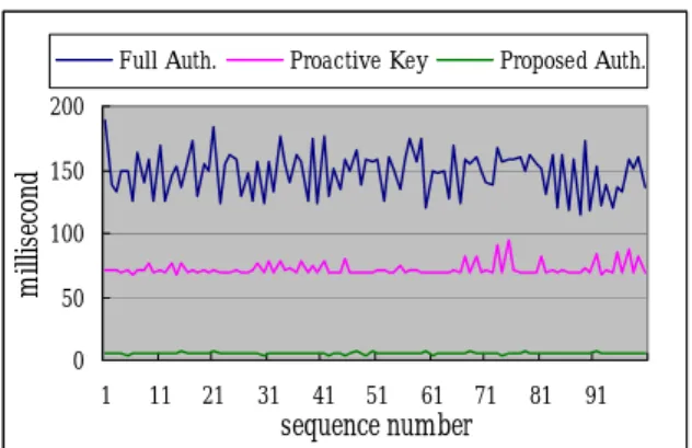
According to the output of the experiment, the handoff latencies of 802.1X connection, Proactive key scheme and the proposed scheme are shown in Figure 6. And the statistical data analyses of handoff latencies
for all schemes are depicted in Table 2. Full connection with 802.1X authentication has most long latency during handoff. 802.1X authentication spends at least a half of handoff time. In the experiment, the AAA server is placed nearby AP. As the AAA server is located apart from AP, the handoff delay of full connection with 802.1X authentication would be much more than the delay in our experiment. Obviously, the proposed protocol needs less time than full connection and proactive key scheme. With comparing to other schemes, the handoff latency improvements of the proposed protocol are depicted in Table 3.
Experiment 2
The experiment about RNG utilizes the mobility data from Dartmouth College to compare the performance of refinement neighbor graph with that of neighbor graph and DSTPA scheme. This mobility data is extracted from the system log portion of the Dartmouth Wireless-Network Traces. The original mobility data include traces from
Full connection Proactive key
Improvement 96% 92%
Table 3 – the latency improvement of the proposed scheme
Average Min. Max.
Full authentication 147.97 114.98 189.71 Proactive key 71.97 67.85 95.07 The proposed scheme 5.36 4.32 7.68 Table 2 – Experiment Results for latency of handoff
0 50 100 150 200 1 11 21 31 41 51 61 71 81 91 sequence number m illis ec on d
Full Auth. Proactive Key Proposed Auth.
Apr. 2001 to June 2004. The Experiment only makes use of mobility data in last year to analyze RNG scheme and other schemes. Since the system log messages are sent from each AP to server as UDP message, it is possible for them to be lost. Moreover, a small number of APs did not send system logs. These situation means that the movement path from one AP to another AP in system log may not be one hop in reality. And some of these mobility data is improper for handoff. As a result, when the movement path which is impossible for handoff over WLAN, we regard it as the situation that STA disconnects to one AP and connects with next AP.
This experiment focuses on Neighbor Graph, DSTPA, and RNG scheme. We implement each scheme that uses the dataset mentioned above. Some parameters are needed to be specified for these schemes except Neighbor Graph. The parameter C of DSTPA that means the maximum number of neighbor AP is set to 3 in the experiment. As for RNG scheme, the experiment set the handoff probability threshold to 0.95 and the handoff number threshold in time span to 100. 0 2 4 6 8 10 1 51 101 151 201 251 301 351 Day M essa ge s/ (R e) A sso ci at io n
Neighbor Graph DSTPA RNG
Figure 7 – Message number on the average
0 0.2 0.4 0.6 0.8 1 1.2 1 51 101 151 201 251 301 351 Day H it Rate
Neighbor Graph DSTPA RNG
Figure 8 – Hit Rate on the average
Figure 7 shows the average number of key exchange when user connects with AP. Figure 8 plots the average rate of prediction hit when user connects with AP. Table 4 contains two columns which represent measured target and three rows which represent each scheme in our experiment. The values in Table 4 are the average results over 365 days that correspond to Figure 7 and Figure 8. From Table 4, the Neighbor Graph scheme has highest hit rate. The hit rate of this scheme is approximately to 1, but the scheme requires larger transmission overhead. The DSTPA incurs the amount of key exchange messages of each connection is 1.67 and the hit rate of the scheme is 0.938. Compared with Neighbor Graph, the DSPTA scheme reduces greatly message while keeping almost the same level of hit rate. Our scheme only incurs the amount of key exchange messages of each connection is 1.15 and the hit rate is 0.398. Obviously, our scheme has lower transmission overhead when we provide the same hit rate of prediction.
Ⅶ. Conclusion
To accelerate handoff procedure, we propose a fast authentication protocol in wireless LAN. The proposed protocol provides key agreement proactively after a STA authenticates successfully to AP in LAN. The proposed protocol can effectively reduce the roaming authentication delay. Moreover, it has no need to make a great deal of modification on WLAN specification. We also propose RNG to determine the neighbor APs that user may roam to in the near future. According the scheme, we can minimize the number of messages in the key
Message Count per (Re)Association
Hit Rate
Neighbor Graph 6.46 0.999 DSTPA 1.67 0.938 RNG 1.15 0.938 Table 4 – Experiment result on average of 365 days
pre-agreement of the proposed authentication protocol.
References
[1] IETF, RFC 2865 “Remote
Authentication Dial In User Service (RADIUS)”, June 2000
[2] IEEE std 802.1X-2001, “Local and
metropolitan area networks –
Port-Based Network Access Control”, Oct. 2001
[3] “IEEE Trial-Use Recommended
Practice for Multi-Vendor Access Point Interoperability via an Inter-Access Point Protocol Across Distribution Systems Supporting IEEE 802.11 Operation”, 80211.f, 14 July 2003.
[4] “Information technology–
Telecommunications and information exchange between systems- Local and metropolitan area networks- Specific requirements- Part 11:Wireless LAN Medium Access Control (MAC) and Physical Layer (PHY) specifications”, IEEE std 802.11-1997.
[5] “Information technology–
Telecommunications and information exchange between systems- Local and metropolitan area networks- Specific requirements- Part 11:Wireless LAN Medium Access Control (MAC) and Physical Layer (PHY) specifications, Amendment 6: Medium Access Control (MAC) Security Enhancements”, IEEE std 802.11i-2004.
[6] International Telecommunication Union, “General Characteristics of International Telephone Connections and
International Telephone Circuits.”, ITU-TG.114. 1988
[7] A. Bhattacharya and S.K. Das
“LeZi-Update: An Information-theoretic framework for personal mobility
tracking in PCS networks”, in ACM/Kluwer Wireless Networks
Journal, vol. 8, no. 2-3 pp.121-135, Mar.
2002
[8] A. Miashra, M. Shin, N.L. Petroni Jr.,
T.C. Clancy and W. Arbaugh, “Proactive Key Distribution Using Neighbor
Graphs” IEEE Wireless Comm. Magazine,
[9] A. Mishra, M. Shin and W. Arbaugh,
“Context Caching using Neighbor Graphs for Fast Handoffs in a Wireless Network”, in Proc of IEEE INFOCOM, Mar. 2004.
[10] A.Mishra, M.Shin, and W.Arbaugh “An
Empirical Analysis of the IEEE 802.11 MAC Layer Handoff Process”, ACM Computer Communication Review, 2003, pp.93-102
[11] H. Velayos, G. Karlsson “Techniques to
reduce the IEEE 802.11b handoff time”, Proceedings of IEEE international Conference on Communications, vol.7, pp. 3844-3848, 2004.
[12] L Maccari, R Fantacci, T Pecorella, F
Frosali, “Secure, fast handoff techniques for 802.1X based wireless network”, IEEE ICC 2006 proceedings.
[13] M. Shin, A. Mishra, W. A. Arbuagh “Improving the latency of 802.11 hand-offs using neighbor graphs”, Proceedings of the 2nd international Conference on Mobile Systems, Applications, and Services, 2004, pp.70-83.
[14] S. Pack, H. Jung, T. Kwon, and Y. Choi
“A Selective Neighbor Caching Scheme for Fast Handoff in IEEE 802.11
Networks”, in Proc. IEEE ICC, May 2005.
[15] S. Pack and Y. Choi, “ Fast Inter-AP
Handoff using Predictive Authentication Scheme in a Public Wireless LAN” in Proc. Of Networks 2002, Aug. 2002.
[16] T. Joshi, A. Mukherjee, and D.P.
Agrawal “Exploiting Mobility Patterns to Reduce Re-Authentication Overheads in Infrastructure WLAN Networks” Electrical and Computer Engineering, Canadian Conference on 2006