Study of argon characteristics in ion physical vapor deposition using molecular dynamics simulation
Chi-Chuan Hwang
a)Department of Engineering Science, National Cheng Kung University, Tainan, Taiwan, Republic of China
Gwo-Jiunn Huang
b)Department of Electrical and Electronics Engineering, University of Wales Swansea, Singleton Park, Swansea SA2 8PP, Wales, United Kingdom
Jee-Gong Chang
c)and Shin-Pon Ju
Department of Mechanical Engineering, National Cheng Kung University, Tainan, Taiwan, Republic of China
共Received 19 October 2001; accepted for publication 13 December 2001兲
This article uses molecular dynamics simulation to investigate the role of Ar ions in the ion physical vapor deposition
共IPVD兲 process for different Ar⫹-to-Cu
⫹ratios, and to analyze the influence of different Ar
⫹-to-Cu
⫹ratios on the trench filling morphology. Also compared are the trench filling morphology observed for the IPVD process with that found in the conventional collimated magnetron deposition process. The molecular dynamics simulation includes a trench model and a deposition model, and uses the many-body, tight-binding potential method to represent the interatomic force acting among neutral atoms. The interatomic force acting between the ions and the neutral atoms is modeled by the pairwise Moliere potential method. The simulation indicates that the incident Ar ions influence the trench filling mechanisms in two significant ways; peeling of the cluster atoms, which promotes migration of the cluster atoms along the sidewall, and breaking of the bridge which forms when two clusters of atoms join. Both phenomena are beneficial since they promote a more complete filling of the trench. © 2002 American Institute of Physics.
关DOI: 10.1063/1.1450032兴
I. INTRODUCTION
The principle behind the development of the ion physical vapor deposition
共IPVD兲 process is the integration of a con-ventional magnetron sputtering system with a high-density argon plasma generated by an induction coil.
1,2In the IPVD process, the atoms to be deposited are first emitted from the magnetron cathode, and then enter an inductively coupled plasma
共ICP兲 region3,4where some of them are subsequently ionized. The fraction of atoms which are ionized, as they pass through this ICP region, can be controlled by adjusting the power of the ICP and the magnetron.
3The direction of the ionized atoms can be controlled by applying a bias po- tential to the substrate. This ability to control the direction of the deposited atoms is the intrinsic advantage of the IPVD method over the collimated sputtering process.
4The direc- tionality feature of the deposited atoms renders the IPVD process particularly suitable for use in filling high aspect ratio trenches, or vias used as multiple-layer interconnects;
4,5a procedure known as the damascene technique. Reference 6 provides an excellent, recent, summary of the historical de- velopment of the IPVD process.
Quite recently, much literature has been presented which investigates the IPVD process through experimentation, or
by employing numerical simulation techniques. The main purpose of these studies has been to investigate the relation- ship between the deposition source and the process control parameters. The deposition source includes the ionized Cu (Cu
⫹), neutral atoms. Cu, and the background ion gas Ar
⫹. Nichols et al.
3investigated the relationship of the Cu
⫹/Ar
⫹ionized ratio to the magnetron power, and to the rf power.
They stated that the Cu
⫹/Ar
⫹ratio can be varied between 0.15 and 1.4, i.e., Ar
⫹/Cu
⫹ranging from 6.67 to 0.7, by adjusting either the ICP power or the magnetron power. In studies from Rossnagel and co-workers,
1,4,7the ratio of metal ionization was observed to reach as high as 90% at relatively low sputtering levels, for the magnetron component of the IPVD process. Cheng and Rossnagel
5used scanning electron microscopy apparatus to carry out a series of experiments to investigate the influence of various process control param- eters, including Ar pressure, rf power, magnetron power, and sample voltage, on the filling morphology. They pointed out that these parameters are directly related to the parameters of ion-to-neutral ratio, total flux, and average ion energy. Their analysis also indicated that these process control parameters have a crucial influence on the successful completion of trench filling.
Hamaguchi and Rossnagel
2,8employed the shock- tracking method to investigate the filling profile evolution within the IPVD process for different aspect ratios, and for different ion-to-neutral flux ratios. However, since their study was based upon a macromodel, several parameters,
a兲Author to whom all correspondence should be addressed; electronic mail:
b兲Electronic mail: [email protected]
c兲Electronic mail: [email protected]
3569
0021-8979/2002/91(6)/3569/10/$19.00 © 2002 American Institute of Physics
including the sticking coefficient and sputtering yield, could not be considered in a rigorous manner. Unfortunately, these parameters are crucial in determining the evolution profile.
Furthermore, it was not possible to observe the detailed mechanisms which occurred during profile evolution.
Although Vyvoda et al.
9also investigated the profile evolution during an IPVD process using the shock-tracking method, his work incorporated an ion reflection, and copper sputtering model. The effects of ion reflection and copper sputtering distribution were investigated separately using molecular dynamics
共MD兲 simulations. The principle aim oftheir analysis was to evaluate the difference in quantitative and qualitative results between their reflection–sputtering approach, and Hamaguchi and Rossnagel’s study,
8which adopted an assumption of isotropic sputtering with no regard to ion reflection. Based upon the results of MD simulation, they concluded that the incorporation of reflection and sput- tering distribution considerations in the analysis yields quali- tatively different evolution shape predictions than when the analysis adopts isotropic sputtering, with no ion reflection.
An implication of this result is that incident atom
共ion兲 re-flection, and sputtering mechanisms which occur during evo- lution of the profile, significantly affect the shape of the pro- file.
It appears that very few attempts have been made to understand the filling mechanisms for the IPVD process by using MD simulation techniques. The major advantage of MD simulation is that several important features such as the sticking of deposited atoms on the surface, or deposited at- oms resputtering from the surface can be incorporated quite naturally within its model, i.e., there is no need to specify these mechanisms separately. This leads to a better under- standing of the filling mechanisms which occur in the evo- lution profile, and the relative influences which these mecha- nisms have on the filling morphology.
The main objective of this article is to use MD simula- tion to investigate the role played by Ar ions (Ar
⫹) in the IPVD process. The role of Ar is evaluated by adjusting the ratio of Ar
⫹-to-Cu
⫹used in the process, and by investigating the influence of different Ar
⫹-to-Cu
⫹ratios on the trench filling morphology. The article also presents a comparison between the trench filling morphology for an IPVD process and for a conventional collimated magnetron deposition pro- cess. The MD simulation incorporates a trench model con- sisting of a thin Ti layer and a thermal control layer, and a deposition model, which characterizes the features of the in- cident Cu (Cu
⫹) atoms
共ion兲 and Ar⫹. The many-body, tight-binding potential method is employed to model the in- teratomic force acting among the neutral atoms, including Cu to Cu, Ti to Ti, and between the deposited Cu atoms and the Ti trench atoms. The pairwise Moliere potential method is adopted to simulate the interatomic force acting between Ar and Cu, and between Ar and Ti.
II. SIMULATION MODEL
The IPVD MD simulation incorporates a trench model, a deposition model, and a potential model. The trench model is established in the form of a thin Ti trench layer with an outer
thermal control layer, whose task is to control the energy transfer through the boundary. The role of the deposition model is to characterize the incident atoms in terms of their spatial and angular distributions. Finally, a potential model is established to simulate the interatomic force which exists among the trench atoms and between the incident atoms and the trench atoms.
A. Trench model
Schematic diagrams of the trench used in the damascene process and the corresponding simplified trench model are shown in Figs. 1
共a兲 and Fig. 1共b兲, respectively. A three-dimensional model is adopted to simulate the trench filling process. It is assumed that the surface of the trench is cov- ered by a Ti barrier film, as indicated by the darker dots in Fig. 1
共b兲, and that the trench filling process does not beginuntil the uniform Ti film is in place. In this way, the influence of low-k dielectric material in the trench on the motion of deposited Cu atoms may be ignored in the simulation, since the Ti film thickness is larger than the truncation distance of the interaction between the low-k material and Cu.
The layers of atoms under the Ti film, indicated as gray dots in Fig. 1
共b兲, are used to control the thermal state of theTi film, and are referred to as the thermal layer henceforth.
FIG. 1.共a兲 Schematic diagram of trench used in damascene process and 共b兲 simplified trench model used in MD simulation.
The Langevin technique
10–14is employed to maintain the thermal layer at a constant temperature, with the result that the outermost layer of the Ti film is also close to a constant temperature. Both the Ti film and the thermal layer are ar- ranged according to their hexagonal-close-packed structure.
The trench constructed by the Ti film and the thermal layer consists of 3080 atoms. The lowest layer is fixed to prevent the trench atoms from shifting, and a periodic boundary con- dition is imposed in the x and y directions.
B. Deposition model
The primary incident atoms in the IPVD process include neutral copper atoms, Cu, ionized copper atoms, Cu
⫹, and ionized argon atoms, Ar
⫹. As mentioned previously, the di- rection of the ionized atoms may be controlled, due to the attraction effects of the negative substrate bias. The voltage potential also increases the kinetic energy of the Cu
⫹and Ar
⫹ions relative to the neutral Cu atoms. The intention of this study is to clarify the role of Ar
⫹played in the IPVD process and to see whether a highly pure Cu plasma consist- ing of nearly 100% ionized Cu
⫹can be produced, without effecting the validity of the results. Therefore, no differentia- tion is made between the incident energy of the Cu and Cu
⫹atoms.
The velocity of the individual atom depends upon the specified incident energy. In this simulation, the angular dis- tribution of the incident atoms is taken to lie within a cutoff angle. It is obvious that the range of deposition angle in the IPVD process is smaller than in either the collimated mag- netron sputtering deposition or in long throw deposition.
Both the incident angle and the incident position of the at- oms are generated by a random distribution function.
It is noted that the distance between two subsequently deposited atoms is set to be larger than their truncated dis- tance. This prevents the incident atoms from interacting with each other before reaching the trench. Strictly speaking, this treatment does not provide a true representation of atom be- havior in a physical IPVD process. In practice, whether or not a collision of atoms occurs before they impact on the trench surface is dependent on the mean free path of the individual incident atoms, which in turn is strongly depen- dent on the chamber pressure.
6The typical operating pres- sure for an IPVD system is approximately equal to 30 mTorr
共⫽4 Pa兲4at a medium vacuum range.
15This level of pressure results in a number of collisions between the sputtered atoms and the background gas. These collisions contribute to an increase in the number of Cu ions generated.
However, in the current simulation, there is no need to consider collisions of incident atoms
共ions兲 before impact onthe trench atoms since the flyway incident atoms
共ions兲which occur as a result of the midair collision make no con- tribution to the filling morphology. However, a consideration of midair collisions may be helpful in estimating the reduc- tion in deposition rate. Nonetheless, for the sake of simplic- ity and without influencing the validity of the results, the current simulation neglects the interaction between incident ions, i.e., between Ar
⫹and Ar
⫹, Ar
⫹and Cu
⫹, and between Cu
⫹and Cu
⫹, as well as the interaction between incident
ions and neutral atoms, i.e., between Ar
⫹and Cu and be- tween Cu
⫹and Cu.
C. Potential model
Atomic interaction in the IPVD process may be classi- fied as follows:
共a兲 interaction between individual Ti trenchatoms and other Ti atoms within the trench,
共b兲 interactionbetween incident Cu
共and Cu⫹兲 atoms and trench Ti atoms, 共c兲 interaction between incident Ar⫹ions and trench Ti at- oms,
共d兲 interaction between incident Cu 共and Cu⫹兲 atomswith Cu atoms deposited previously, or
共e兲 interaction be-tween incident Ar
⫹ions and previously deposited Cu atoms.
The situation is made complicated by the fact that atomic interaction occurs not only between ions and neutral atoms, but also between neutral atoms. In a recent investigation,
16it was reported that the incident ion is neutralized well before impact by a fast Auger process or by resonance, and conse- quently, it is possible to simplify the interaction of ions with neutral atoms to an interaction of neutral atoms with neutral atoms. This approach has been adopted in several previous MD simulations of ion-related processing,
17–19and the re- sults have been in good agreement with experimental results.
This article adopts the many-body, tight-binding poten- tial method to model the atomic interaction among the Cu atoms, the Ti atoms, and between the Cu atoms and the Ti atoms. The remaining interatomic forces, i.e., between Ar and Cu and between Ar an Ti are modeled using the Moliere potential method.
The many-body potential of the tight-binding potential method
20,21begins by summing the band energy, which is characterized by the second moment of the d-band density of state, and a pairwise potential energy of the Born–Mayer type,
21i.e.,
E
i⫽⫺再
兺j
2exp 冋
⫺2q冉 r r
i j0⫺1冊册 冎
1/2⫹兺j
A exp 冋
⫺p冉 r r
i j0⫺1冊册 ,
共1兲where is an effective hopping integral, r
i jis the distance between atom i and j, and r
0is the first-neighbor distance.
The parameters A, p, q and are determined by the experi- mental data of cohesive energy, lattice parameter, bulk modulus, and two shear elastic constants
关C44and C ⬘
⫽1/2(C11⫺C12
)
兴, respectively. The parameters of tight-binding potential related to Cu–Cu and Ti–Ti simulated in this study, are listed in Table I
共and are as stated in Ref. 22兲.Minimal data seems to exist in literature about the param- eters describing the interatomic potential of Cu–Ti. Rather than using a rigorous mathematical or theoretical approach to determine the precise value of these parameters, it is conve-
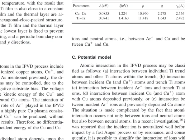
TABLE I. Parameters used in tight-binding potential.
Parameters A共eV兲 共eV兲 p q r0(Å)
Cu–Cu 0.0855 1.224 10.960 2.278 2.556
Ti–Ti 0.0741 1.4163 11.418 1.643 2.492
nient to take an average of the relevant parameters derived from the pure interatomic potential Cu–Cu and Ti–Ti.
23,24The pairwise Moliere potential method is adopted to simulate the interatomic force acting between the high en- ergy ions and the neutral atoms. The repulsion force is rep- resented by an exponential decayed function, and is only dependent on neutral charges and internuclear distance. The Moliere potential is introduced in Ref. 25 as
V
共r兲⫽Z
1Z
2e
2r
i j 共0.35e⫺0.3ri j/a⫹0.55e⫺1.2ri j/a⫹0.1e⫺6.0ri j/a兲, 共2兲
where a is the Firsov screening length, given by a
⫽0.4683共Z11/2⫹Z2
1/2兲⫺2/3
,
共3兲where Z
1and Z
2are the atomic numbers of the relevant ion and the neutral atom, respectively.
One simplification made within the current simulation is that the Ar ion is removed from the system after it has com- pleted its first collision cycle with Cu, i.e., impact with the Cu atom, followed by a rebound motion. In practical com- putation terms, the Verlet list is examined to determine when this collision cycle occurs, i.e., the point at which there is a sudden increase in the number of neighboring atoms to the Ar ion
共collision兲, followed by a sudden decrease 共rebound兲.One of the main reasons for this simplified treatment of the Ar ion collision with trench atoms is that most of the energy of the ion is transferred to the trench atoms during the first collision. Another consideration is that it is extremely expen-
sive in computing terms if the simplified treatment of Ar ion collision is not adopted. It is worth noting that this simplified treatment has been adopted in literature for collision between Ar ions and Si substrate atoms.
26Finally, the interaction force can be derived by taking the first differentiation of Eqs.
共1兲 and 共2兲 for different atominteractions. In the computation, the leapfrog algorithm
27is used to calculate the trajectories of atoms in the simulation.
III. RESULTS AND DISCUSSION A. Conventional deposition
1. Filling morphology for different deposition angles Figures 2
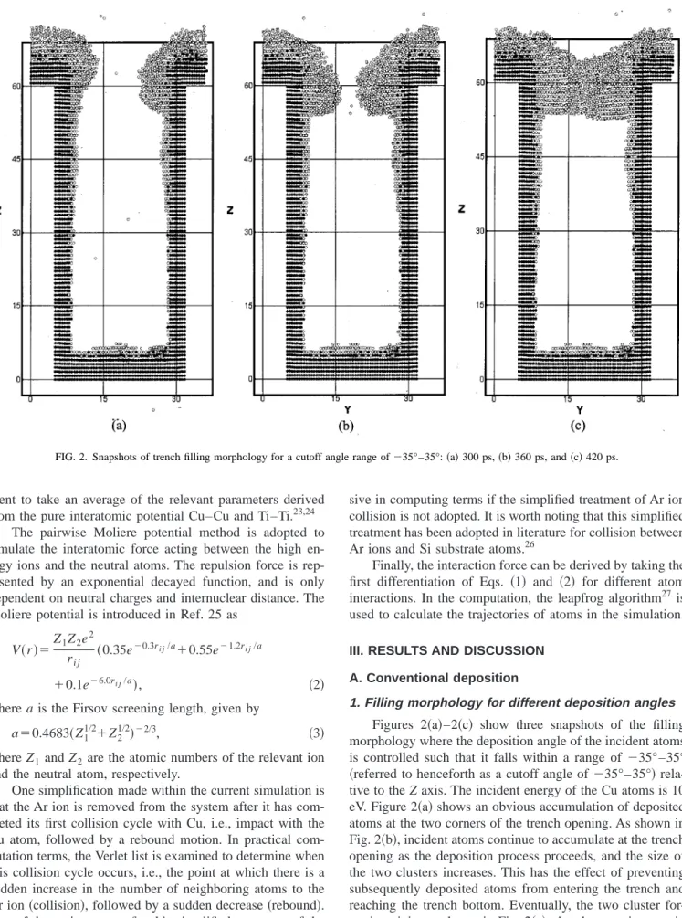
共a兲–2共c兲 show three snapshots of the fillingmorphology where the deposition angle of the incident atoms is controlled such that it falls within a range of
⫺35°–35°共referred to henceforth as a cutoff angle of ⫺35°–35°兲 rela-
tive to the Z axis. The incident energy of the Cu atoms is 10 eV. Figure 2
共a兲 shows an obvious accumulation of depositedatoms at the two corners of the trench opening. As shown in Fig. 2
共b兲, incident atoms continue to accumulate at the trenchopening as the deposition process proceeds, and the size of the two clusters increases. This has the effect of preventing subsequently deposited atoms from entering the trench and reaching the trench bottom. Eventually, the two cluster for- mations join, as shown in Fig. 2
共c兲, thereby trapping a voidwithin the trench. A close observation of Fig. 2
共a兲 shows thatthere is a thin covering of deposited atoms along the side- walls and also on the bottom of the trench. It can be deduced
FIG. 2. Snapshots of trench filling morphology for a cutoff angle range of⫺35°–35°: 共a兲 300 ps, 共b兲 360 ps, and 共c兲 420 ps.
that these atoms are deposited in the trench during the initial deposition stages, since observation of Figs. 2
共b兲 and 2共c兲shows that there is little change in the thickness of these layers as the deposition process continues. The extent to which the sidewalls and the trench bottom are covered by deposited atoms is strongly related to the angular distribution of the atoms during the deposition process. For example, when a wider cutoff angle is specified, the probability of the deposited atoms reaching the trench bottom is much less than the probability of it reaching the trench opening and forming an overhanging cluster. Only where the deposition angle ap- proaches 0° is it more probable that the atoms will reach the trench bottom. The influence of the deposition angle is wor- thy of further discussion which is presented next.
Figure 3 shows the filling morphology for an extreme deposition angle, i.e., the deposition angle is controlled to lie with a cutoff angle of
⫺5°–5°. Actually, it is not easy tocontrol the deposition angle within such a narrow range in the usual collimated magnetron deposition process, or in long throw deposition. However, simulation of this ‘‘unreal- istic’’ cutoff angle is provided within this article for compari- son purposes with subsequent simulation results of the IPVD process, which does use a
⫺5°–5° cutoff angle in practice.Figure 3 demonstrates that the narrower the range of depo- sition angle, the more probable it is that incident atoms will enter the trench. As may be seen by comparing Figs. 2
共c兲 and3, this result is beneficial in improving trench coverage, par- ticularly that of the trench bottom. Figure 3 shows quite clearly that the filling morphology at the trench bottom is bulgy at the center, and flat close to the two sidewalls. This indicates that one effect of the initial cluster formation at the corners of the trench opening is to prevent free movement of
subsequent incident atoms to the bottom corners of the trench.
B. Ion physical vapor deposition
The simulation conditions adopted in the IPVD investi- gation are as follows:
共a兲 Cu incident energy of 10 eV, 共b兲 Arincident energy of 20 eV,
共c兲 cutoff angle in the range ⫺5°–5°, and
共d兲 thermal control layer maintained at a constanttemperature of 300 K.
1. Filling morphology for an Ar-to-Cu ratio of 1 Figures 4
共a兲–4共d兲 show four snapshots of the fillingmorphology for an Ar-to-Cu
共also Ar⫹-to-Cu
⫹兲 ratio of 1.Figure 4
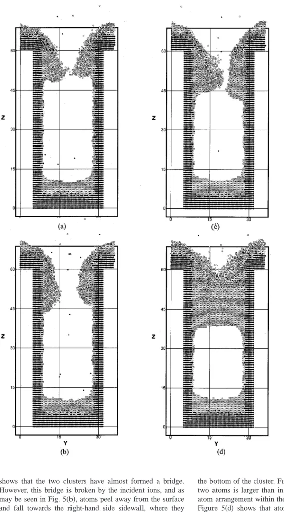
共a兲 shows the instant during the deposition processwhen the two cluster formations have grown to such a point that they are almost touching. Inspection of the shape of the clusters forming along the two sidewalls indicates that the incident Ar ions cause a peeling away of the atoms on the cluster surface. Close observation of the filling morphology at the trench bottom shows that the layer of deposited atoms is slightly concave in shape
关the concave nature of this layeris more obvious in a later simulation result, i.e., Fig. 6
共a兲兴.This may be attributed to a resputtering effect of atoms al- ready deposited at the trench bottom caused by the subse- quent arrival of highly energetic incident atoms. This resput- tering mechanism is one of the main features of the IPVD process, and leads to a conformal growth on the sidewalls.
6,28Comparing the results of Fig. 4 with those in Fig. 3, shows that the resputtering of the atoms at the trench bottom com- pensates for the lack of coverage in the bottom corners of the trench caused by cluster formation. In Fig. 4
共b兲, it can beseen that the gap between the two clusters has opened up, and that the clusters have migrated along the two sidewalls towards the bottom of the trench. From the results of Figs.
4
共a兲 and 4共b兲, it can be deduced that one role played by theincident ion is to provide sufficient kinetic energy to break the linkage between the two cluster formations. Part of the kinetic energy of the incident ion is transferred to the cluster atoms, thus enabling a migration of the clusters along the trench sidewalls.
Figure 4
共c兲 shows that subsequently deposited atomscause the cluster formations to continue to grow in size, causing the gap between them to close. In Fig. 4
共d兲, it can beseen that the two clusters finally join together to form a bridge across the trench. Additionally, the bridge thickness in Fig. 4
共d兲 shows it to be thicker than the bridge formationshown in Fig. 4
共a兲. The incident Ar ions do not possess suf-ficient kinetic energy to break the link between the two clus- ters, and therefore no more atoms are able to reach the bot- tom of the trench. This results in a void being trapped within the trench, as shown in Fig. 4
共d兲, which shows the fillingmorphology at an instant of 700 ps.
2. Filling morphology for an Ar-to-Cu ratio of 2 Figures 5
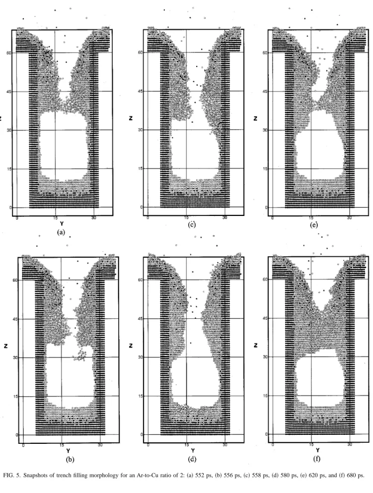
共a兲 to 5共f兲 show six snapshots of the fillingmorphology for an Ar-to-Cu ratio of 2. As the Ar-to-Cu ratio increases, the peeling away effect of atoms from the cluster surface also increases
关Figs 5共a兲 and 5共b兲兴. Figures 5共a兲–5共c兲provide a clear illustration of this peeling effect. Figure 5
共a兲FIG. 3. Final trench filling morphology for a cutoff angle range of⫺5°–5°.
shows that the two clusters have almost formed a bridge.
However, this bridge is broken by the incident ions, and as may be seen in Fig. 5
共b兲, atoms peel away from the surfaceand fall towards the right-hand side sidewall, where they subsequently become attached
关Fig. 5共c兲兴. It should also benoted that the cluster atoms along the left-hand side sidewall are also activated to a state of motion, particularly those at
the bottom of the cluster. Furthermore, the distance between two atoms is larger than in their equilibrium state, and the atom arrangement within the cluster is randomly distributed.
Figure 5
共d兲 shows that atoms have peeled away from theleft-hand side cluster and have migrated a distance along the left-hand side sidewall. Inspection of the atom arrangement within both the left- and the right-hand side clusters shows
FIG. 4. Snapshots of trench filling morphology for an Ar-to-Cu ratio of 1:
共a兲 400 ps, 共b兲 410 ps, 共c兲 500 ps, and 共d兲 700 ps.
that the atoms are closer to an equilibrium state than that in Fig. 5
共c兲. Figures 5共e兲 and 5共f兲 show a gradual accumulationof subsequently deposited atoms within the open channel formed by the peeling and migration mechanisms described
previously. It is observed that under the impact from incident atoms, the atoms previously deposited in the region of the open channel are pushed towards the bottom of the channel, causing the channel to gradually close. Since the kinetic en-
FIG. 5. Snapshots of trench filling morphology for an Ar-to-Cu ratio of 2:共a兲 552 ps, 共b兲 556 ps, 共c兲 558 ps, 共d兲 580 ps, 共e兲 620 ps, and 共f兲 680 ps.
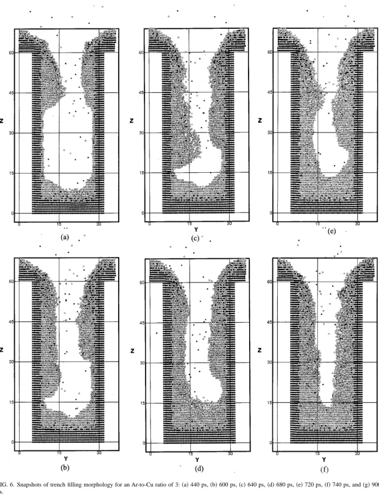
FIG. 6. Snapshots of trench filling morphology for an Ar-to-Cu ratio of 3:共a兲 440 ps, 共b兲 600 ps, 共c兲 640 ps, 共d兲 680 ps, 共e兲 720 ps, 共f兲 740 ps, and 共g兲 900 ps.
ergy imparted by successive incident Ar ions is insufficient to prevent the bridge formation, the thickness of the bridge increases, and a void track is formed within the trench. How- ever, a comparison of Figs. 5
共f兲 and 4共d兲 indicates that thevoid size apparently decreases as the Ar-to-Cu ratio in- creases.
3. Filling morphology for an Ar-to-Cu ratio of 3 Figures 6
共a兲 to 6共g兲 show seven snapshots of the fillingmorphology for an Ar-to-Cu ratio of 3. Figure 6
共a兲 shows thefilling morphology at the initial stage of the deposition pro- cess. As mentioned previously, the atom layer at the bottom of the trench exhibits a concave shape due to the resputtering effect. The concave effect is much more marked in this case than in the situation shown in Fig. 4
共a兲, suggesting that theresputtering effect of atoms at the trench bottom increases as the Ar-to-Cu ration increases. As well as the resputtering mechanism, beveling of the two corners at the trench open- ing is also a main feature of the IPVD process.
6,28This in- hibits contact between the two cluster formations at the trench opening. The beveling effect associated with the IPVD process is apparent when comparing Figs. 6
共a兲 and2
共a兲, which show the filling morphology for conventionaldeposition. In Fig. 6
共a兲, the clusters overhanging the trenchopening are clearly bevelled under the influence of the inci- dent Ar ions, while those in Fig. 2
共a兲 are rounded, and assuch have the propensity to lead to a bridging effect. Figures 6
共b兲–6共d兲 show the peeling sequence of the left-hand sidecluster caused by the incident Ar ions. It can be seen from
Figs. 6
共b兲 and 6共c兲 that the atoms are peeled from the surfaceof the upper part of the cluster and fall toward the bottom of the cluster, where they form a significant bulge. In Fig. 6
共d兲,it is apparent that this bulge has collapsed, filling the previ- ously unoccupied void below it. Figures 6
共e兲–6共f兲 show thesequence of subsequent peeling activity and that peeling oc- curs on both sides of the trench. As shown in Fig. 6
共f兲, theunoccupied void has a slender triangle shape. This is further evidence that cluster atoms are peeled from the upper part of the trench. It should also be noted that trench filling occurs progressively, from the bottom of the trench toward the trench opening. Figure 6
共g兲 shows a later snapshot of thefilling morphology, in which a filling of the trench has been achieved due to peeling atoms from the upper part of the cluster atoms successively filling the lower unoccupied space.
C. Comparison between conventional deposition and ion physical vapor deposition
Previous results for the conventional deposition method have shown that it is challenging to fill the trench, even when the direction of the incident atoms is controlled. This indi- cates that high directionality of the incident atoms is not the only factor leading to a filled trench. As demonstrated by the IPVD simulation results, the trench still can not be com- pletely filled, even with the assistance of an incident Ar ion.
However, the incident ion does provide additional kinetic energy to those atoms already deposited along the sidewalls of the trench, thereby promoting their migration. Further- more, the incident ion breaks the bridge formed by growth of the two cluster formations on the sidewalls.
IV. CONCLUSION
This article has presented an investigation into the IPVD filling morphology by means of MD simulation, with par- ticular emphasis placed on the role of the Ar ion within the process. It has been determined that the chief contribution of the Ar ion is to transfer kinetic energy to the atoms within the cluster formations generated during the deposition process.
There are two principle outcomes as a result of this energy transfer. First, there is a peeling away of atoms from the cluster surface, which enables the cluster atoms to migrate along the sidewalls of the trench, resulting in a more com- plete filling of the trench. Second, the bridge which forms as the clusters grow in size is broken, allowing more atoms to reach the trench bottom, and therefore achieving a more complete filling of the trench. The latter mechanism is spe- cific to the IPVD process. In the conventional ion assisted deposition
共IAD兲 process, the role of the incident ion is totransfer kinetic energy to the surface atoms, thus increasing the surface mobility of the deposited film. Too large an ion incident energy causes an excessive resputtering of atoms from the surface, which in turn leads to poor surface proper- ties of the produced film. However, the destructive features of the ion energy in the IAD process are turned into an ad- vantage in the IPVD process where they are used to break the cluster bridge, thus allowing trench filling to proceed.
FIG. 6.共Continued.兲
ACKNOWLEDGMENT
The authors gratefully acknowledge the support given to this research project by the National Science Council, Re- public of China, under Grant No. NSC90-2212-E-006-099.
1S. M. Rossnagel and J. Hopwood, J. Vac. Sci. Technol. B 12, 449共1994兲.
2S. Hamaguchi and S. M. Rossnagel, J. Vac. Sci. Technol. B 14, 2603 共1996兲.
3C. A. Nichols, S. M. Rossnagel, and S. Hamaguchi, J. Vac. Sci. Technol.
B 14, 3270共1996兲.
4S. M. Rossnagel, J. Vac. Sci. Technol. B 16, 3008共1998兲.
5P. F. Cheng and S. M. Rossnagel, J. Vac. Sci. Technol. B 13, 203共1995兲.
6S. M. Rossnagel, J. Vac. Sci. Technol. B 16, 2585共1998兲.
7S. M. Rossnagel and J. Hopwood, Appl. Phys. Lett. 63, 3285共1993兲.
8S. Hamaguchi and S. M. Rossnagel, J. Vac. Sci. Technol. B 13, 183 共1995兲.
9M. A. Vyvoda, C. F. Abrams, and D. B. Grave, IEEE Trans. Plasma Sci. 5, 1433共1999兲.
10R. Biswas and D. R. Hamann, Phys. Rev. B 34, 895共1986兲.
11H. J. C. Berendsen, J. P. M. Postma, W. F. van Gunsteren, A. DiNola, and J. R. Haak, J. Chem. Phys. 81, 3684共1984兲.
12C. Kim, H. Kang, and Seung C. Park, Nucl. Instrum. Methods Phys. Res.
B 95, 171共1995兲.
13Z. Insepov and I. Yamada, Mater. Sci. Eng., A 217, 89共1996兲.
14X. W. Zhou, R. A. Johnson, and H. N. G. Wadley, Acta Mater. 45, 1513 共1997兲.
15A. A. R. Elshabini and F. D. Barlow III, Thin Film Technology Handbook 共McGraw–Hill, New York, 1998兲.
16G. A. Kimmel and B. H. Cooper, Phys. Rev. B 48, 12164共1993兲.
17D. E. Hanson, A. F. Voter, and J. D. Kress, J. Appl. Phys. 82, 3552共1997兲.
18D. G. Coronell, D. E. Hansen, A. F. Voter, C. L. Liu, X. Y. Liu, and J. D.
Kress, Appl. Phys. Lett. 73, 3860共1998兲.
19J. D. Kress, D. E. Hanson, A. F. Voter, C. L. Liu, X. Y. Liu, and D. G.
Coronell, J. Vac. Sci. Technol. A 17, 2819共1999兲.
20F. Cleri and V. Rosato, Phys. Rev. B 48, 22共1993兲.
21V. Rosato, M. Guillope, and B. Legrand, Philos. Mag. A 59, 321共1989兲.
22F. Cleri and V. Rosato, Phys. Rev. B 48, 22共1993兲.
23M. Ladeveze, G. Treglia, P. Muller, and F. Arnaud d’Avitaty, Surf. Sci.
395, 317共1998兲.
24T. Iwasaki, Computational Mech., Berlin 25, 78共2000兲.
25K. H. Muller, Phys. Rev. B 35, 7690共1987兲.
26B. Strickland and C. Roland, Phys. Rev. B 51, 5061共1995兲.
27J. M. Haile, Molecular Dynamic Simulation共Wiley, New York, 1992兲.
28T. S. Cale, T. P. Merchant, L. J. Borucki, and A. H. Labun, Thin Solid Films 365, 152共2000兲.