國科會 專題研究計畫成果報告書
主題: 針對大容量快閃記憶體儲存系統的 快閃記憶體轉換層之研究
編號: 96-2218-E-011-011-
計畫主持人: 吳晉賢 助理教授(台科大電子工程系)
報告內容: 第一頁到第六頁 參考文獻: 第六頁
計畫成果自評: 第七頁
部 份 計 畫 內 容 已 發 表 在 國 際 會 議 論 文 : The 6th IEEE/ACS International Conference on Computer Systems and Applications, March 31 - April 4, 2008, Doha, Qatar
A Flash Translation Layer for Huge-Capacity Flash Memory Storage Systems
Abstract— The capacity of flash-memory storage systems grows at a speed similar to many other storage systems. In order to properly manage the product cost, vendors face serious challenges in system designs. In this paper, an efficient flash translation layer is proposed with low memory requirements. The objective of the design is to provide efficient address mapping with low garbage collection overhead, provided that memory space requirement for the flash translation layer is properly managed.
The capability of the design is evaluated over realistic workloads.
I. I
NTRODUCTIONFlash memory has become a popular alternative in storage system implementations, due to its characteristics in non-volatility, shock- resistance, and low power consumption. Because of recent technol- ogy breakthroughs, flash-memory storage systems are much more affordable than ever. Similar to other storage media, the capacity of flash memory chips is doubled every two years. Because of the cost management issues, vendors face tremendous challenges in the design and implementation of block-device emulation software in flash management. In particular, the amount of main memory in flash- memory management must be under control so that related products remain competitive in the markets.
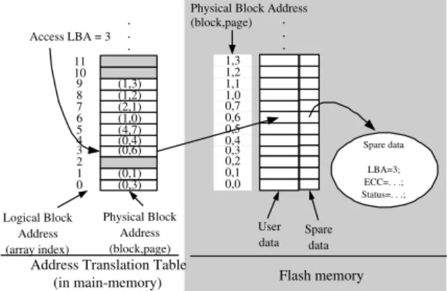
Flash memory consists of a number of blocks, and each block is of a fixed number of pages (e.g., 32 pages). A page contains a user area and a spare area, where the user area is for the storage of a logical block, and the spare area stores ECC and other house- keeping information (i.e., LBA). The typical sizes of the user area and spare area of a page are 512B and 16B, respectively. Reads and writes are in the unit of a page. Because of the very distinct characteristics of flash memory, the management of flash memory is significantly different from those based on disks. In particular, flash memory is write-once such that updates to existing data on a page are only possible after an erase operation is done over the residing block. Data must be written to free space, and the old versions of data are invalidated. Therefore, free space on flash memory could become low after a number of writes, and garbage collection in the recycling of available space on flash memory will start. In order to resolve the write-once and the garbage collection problems for data on flash memory, a flash translation layer is proposed to emulate flash memory as block devices such that many existing file systems, e.g., FAT/DOS, EXT/EXT2, and NTFS, could be built over flash memory without any modification. A flash translation layer usually has a RAM-resident translation table, where each entry of the table (indexed by LBA’s) contains the PBA of the corresponding LBA, as shown in Figure 1. Note that LBA’s are addresses of pages mentioned by the operating system, but each PBA has two parts: The residing block number and the page number in the block.
In particular, the NAND Flash Translation Layer (NFTL) is pro- posed and popularly adopted for the flash-memory management of large-scale flash-memory storage systems [5], [2]. It provides coarse- grained address translation to map each given logical block address (LBA) of an access to a physical address on flash memory, where the unit in reads and writes is a page, and the mapping is done at the block level (to be explained in a late section). Although
User data . . .
Logical Block Address (array index)
Physical Block Address (block,page)
Physical Block Address (block,page) Access LBA = 3
Address Translation Table
(in main-memory) Flash memory
0,0 0,1 0,2 0,30,4 0,5 0,6 0,7 1,0 1,1 1,2 1,3
(0,3) (0,1) (0,6) (0,4) (4,7) (1,0) (2,1) (1,2) (1,3)
0 1 2 34 5 6 7 8 9 10 11
. . .
Spare data
Spare data
LBA=3;
ECC=. . .;
Status=. . .;
Fig. 1. A RAM-resident Translation Table
NFTL-like coarse-grained mapping designs are fine with current products, they soon become improper in the near future. It is because the rapid growing of the storage-system capacity results in the significant increasing of the main memory needs in flash-memory management. Such an observation motivates this research. In this paper, we propose an efficient design of a flash translation layer for huge-capacity flash-memory storage systems. An address-mapping mechanism that consists of a coarse-grained translation table (CGTT) and a fine-grained translation table (FGTT) is proposed. CGTT aims at the efficient handling of address mapping for large chunks of data accesses, and FGTT is to provide fast address mapping and a swapping mechanism. A garbage collection mechanism is then proposed to better manage the overhead.
The rest of this paper is organized as follows: Section II is the related work and the research motivation. Section III presents the to-be-proposed flash translation layer. Section IV provides the performance evaluation. Section V is the conclusion.
II. R
ELATEDW
ORK ANDM
OTIVATIONA. A NAND Flash Translation Layer
In recent years, issues on flash-memory management had drawn a lot of attention. Excellent research results and implementations have been reported on performance enhancement, especially on garbage collection and system architecture designs [5], [8], [11], [12], [13], [14], [15], [16]. In particular, the NAND Flash Translation Layer (NFTL) is proposed and popularly adopted for the flash-memory management of large-scale flash-memory storage systems [5], [2] so that some NFTL-like flash translation layers [6], [7], [16] are also proposed. NFTL provides coarse-grained address translation to map each given logical block address (LBA) of an access to a physical address on flash memory, where the unit in reads and writes is a page, and the mapping is done at the block level.
NFTL represents a typical coarse-grained design of a flash transla-
tion layer [5], [2]. An LBA under NFTL is divided into a virtual block
address and a block offset, where the virtual block address (VBA)
! " ! "
! "
#
Fig. 2. NFTL
is the quotient of the division of the LBA by the number of pages per block, and the block offset is the remainder of the division. Each VBA is associated with a primary block and a replacement block.
When a write request is issued, the content of the write request is written to the page with the corresponding block offset in the primary block. Because flash memory is write-once, any subsequent write of the same LBA is written to first free page in the corresponding replacement block. When all of the pages of a replacement block are consumed, garbage collection starts by copying the valid pages of the corresponding primary block and the replacement block into a new primary block and then erasing the two blocks for recycling. Figure 2 shows the resulted primary block and its replacement block when write requests to LBA’s A = 100, B = 101, and F = 105 are done for 2 times, 8 times, and 1 time. Any further write to A, B or F would result in garbage collection, as shown in Figure 2.
B. Motivation
NFTL-like address translation must maintain an address transla- tion table for block-level address translation. Consider a 256MB NAND-flash-memory storage system: Let the page size be 512 bytes, and each block consist of 32 pages. A table for block-level address translation will have 16,384 (256*1024/16) entries. Suppose that each entry needs 8 bytes. The address translation table for 256MB NAND flash memory will already occupy 128KB of the main memory. Similar to other storage media, the capacity of flash memory chips is doubled every two years. A example update in the market is the availability of 32Gbit flash memory chips (SAMSUNG K9NBG08U5A). It would be simply not acceptable to most vendors to use 16MB main memory merely for address translation in a 32GB flash-memory storage system. The amount of main memory in flash- memory management must be under control so that related products remain competitive in the markets. Such an observation motivates this research.
III. A F
LASHT
RANSLATIONL
AYERD
ESIGNA. Overview
In this section, a flash translation layer under low memory require- ments is proposed for huge-capacity flash-memory storage systems, referred to as HF T L. HFTL provides block-device emulation of flash memory such that common file systems can be built over it without any modification. HFTL consists of three parts: coarse- grained address translation, fine-grained address translation, and garbage collection, as shown in Figure 3. Coarse-grained and fine- grained address translation come with a coarse-grained translation ta- ble (CGTT) and a fine-grained translation table (FGTT), respectively.
Garbage Collection task
A Fine-Grained AddrTM
Flash Memory HFTL File system (FAT, NTFS, ext2...) fwrite(file,data)
Block write (LBA,size)
Flash I/O Requests
Control signals
File Systems
A Coarse- Grained AddrTM task task task
Fig. 3. System Architecture
CGTT aims at the efficient handling of address mapping for large chunks of data accesses, and FGTT is to provide fast address mapping and a swapping mechanism. CGTT consists of coarse-grained slots, and each coarse-grained slot is for the mapping of a large address chunk (also referred to as a segment). Let the flash memory size be F MB, and each segment size be S MB. The number of coarse-grained slots is F/S. FGTT consists of fine-grained slots, and the maximum number of fine-grained slots in FGTT can be pre-determined as needed.
When a read operation is issued, a fine-grained slot in FGTT is searched for quick address mapping. If the corresponding fine-grained slot can not be found, then the corresponding fine-grained slot could be located from the swap area that is stored in flash memory. The physical address of the swap area is maintained by CGTT. The swap area is to store fine-grained slots (from FGTT) over flash memory, due to the size limit of FGTT. When a write operation is issued, a free page will be consumed, and CGTT is updated to reflect the usage of free pages (and related information). Fine-grained slots could be also added into FGTT to reflect any new address mapping. Due to the large-chunk address mapping, the garbage collection overhead could be huge in the recycling of invalid data over the segment (Please see Section 3.3). HFTL provides four cases ordered by execution priorities to reduce the garbage collection overhead as much as possible.
B. An Address-Mapping Mechanism
1) Coarse-Grained and Fine-Grained Translation Tables: Be- cause flash memory is write-once, data can not be overwritten over existing pages. Instead, data are written to free pages, and the old versions of data are invalidated and considered being dead. In order to resolve the residing location problem for data on flash memory, specific data structures must be designed to emulate flash memory as block devices. In this section, two data structures are proposed for efficient address mapping: the coarse − grained translation table (CGTT) and the f ine−grained translation table (FGTT). HF T L must ensure that the two data structures not only occupy small memory space but also provide efficient address mapping.
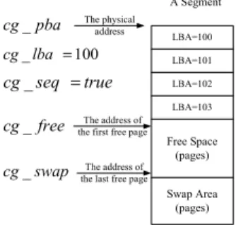
The coarse-grained translation table consists of coarse-grained slots, and each coarse-grained slot is defined as a tuple (cg lba
1, cg lba
2, cg f ree
1, cg f ree
2, cg pba
1, cg pba
2, cg seq
1, cg seq
2, cg swap
1, cg swap
2), where each coarse-grained slot can provide an address mapping for large address chunks (segment). cg lba
1denotes the corresponding logical address of the first page in the
segment SEG whose physical address is cg pba
1. cg f ree
1denotes
an address of the first free page in the segment SEG. When cg seq
1!
! =
=
!
!
!
Fig. 4. A Coarse-Grained Slot
is true, it denotes that all corresponding logical addresses of all consecutive written pages in the segment SEG are in sequential order. Note that cg lba
2, cg f ree
2, cg pba
2, and cg seq
2have the same meaning to describe the other (replacement) segment if needed.
The fine-grained translation table consists of fine-grained slots, and each fine-grained slot is defined as a tuple (f g lba, f g pba, size), where f g lba and size denote the starting logical address and the size of the range of a logical address space, respectively. Since sequential updates of a write request could be stored in a continuous space in flash memory, f g pba denotes the starting physical address in flash memory (i.e., the physical page address in flash memory) to store the write request.
2) Address Mapping with CGTT: When a write request (LBA=α) is issued, the corresponding coarse-grained slot slot
cgcan be re- trieved by quickly index-searching CGTT:
•
If slot
cg.cg pba
1and slot
cg.cg pba
2are nullified, then HFTL should create a new segment, and slot
cg.cg pba
1should reflect the new segment address. Then the write request writes data to the first page of the segment and slot
cg.cg f ree
1is set as 1 to indicate that the second page is a free page.
•
If slot
cg.cg pba
2is nullified, then the write request writes data to the free page whose address is slot
cg.cg f ree
1, and slot
cg.cg f ree
1is then increased. If all of the free pages of the segment (slot
cg.cg pba
1) are used, then HF T L should create a new replacement segment, and slot
cg.cg pba
2should reflect the new replacement segment address.
•
If slot
cg.cg pba
2is not nullified, then the write request writes data to the free page whose address is slot
cg.cg f ree
2, and slot
cg.cg f ree
2is then increased. If all of the free pages of the segment (slot
cg.cg pba
2) are used, then HFTL should invoke garbage collection, as shown in Section III-C.
3) Address Mapping with FGTT: After the write request with LBA=α is processed by CGTT, a fine-grained slot would be created and inserted into FGTT. However, if the write request (LBA=α) writes data to the segment such that all logical addresses (including α) of the written pages are in a continuous and sequential order, then HFTL does not create a fine-grained slot, and the corresponding slot
cg.cg seq
1or slot
cg.cg seq
2is set as true. As a result, CGTT adopts slot
cg.cg seq
1and slot
cg.cg seq
2to reflect the distribution of LBA’s in the primary and replacement segments. On the other hand, if the write request (LBA=α) breaks the continuous and sequential order, then two fine-grained slots should be created and inserted into FGTT. One is for the description of the write request (LBA=α), and the other is for the description of the segment before the the write request (LBA=α).
Because CGTT adopts the address mapping for large address chunks, the performance of read requests could be deteriorated, due to
linear searches of large address chunks. However, fine-grained slots in FGTT can provide fast address mapping such that the performance of read requests can be improved. For example, consider the case when a read request with LBA=β is issued. Suppose that one fine- grained slot Slot
f gcan be retrieved from FGTT, where β is in the range [Slot
f g.f g lba,Slot
f g.f g lba+Slot
f g.size). Then, the data in physical address (Slot
f g.f g pba+β-Slot
f g.f g lba) can be read directly. Because the number of fine-grained slots is limited, FGTT must reduce the number of invalid fine-grained slots as much as possible. Similar objective and methods can be found in the paper [14], [16].
4) Main Memory Requirements: The number of coarse-grained slots in CGTT can be calculated based on the size of each segment and the size of flash memory. Suppose that each segment is of 4MB, and the flash memory capacity is 20GB. The number of coarse-grained slots is (20*1024/4)=5120. If each coarse-grained slot is of 10B, then the required memory size of CGTT is 50K.
CGTT is a necessary data structure, and its memory size must be reserved by HFTL. The number of fine-grained slots in FGTT is a pre-determined as needed. It is to limit the total memory space requirements for HFTL. In the experiments, we shall show different system performance with different memory space consumption for HFTL.
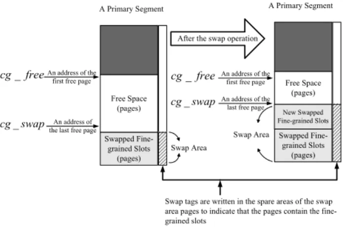
When the number of fine-grained slots is over a pre-determined parameter, we propose to swap some fine-grained slots to the flash memory. When the swapped fine-grained slots are needed, HFTL reloads the fine-grained slots from flash memory to CGTT. Obviously, the executions of swap operations is an overhead to HFTL. The swapped fine-grained slots are written to the corresponding segment, and cg swap
1or cg swap
2of the segment are updated accordingly.
Here cg swap
1and cg swap
2denote the last free page addresses of the primary segment and the replacement segment, respectively.
As shown in Figure 5, the swapped fine-grained slots are written to the primary segment upwardly from cg swap
1. When free pages of the primary segment are used up, the swapped fine-grained slots are written to the corresponding replacement segment upwardly from cg swap
2. If all of the free pages of the primary segment and the replacement segment are used up, garbage collection must be executed to recycle the invalid pages (Please see Section III-C).
Special swap tags must be written to the spare areas of the (swap area) pages to indicate that the pages contain swapped fine-grained slots. The space needed for the swap tag can be allocated in the spare area, and there are undefined regions in the area for such usages. The purpose of the swap tags is to locate fine-grained slots, especially when reload operations or system initialization is invoked.
C. A Garbage Collection Mechanism
When all of the pages of a primary segment and the corresponding replacement segment are used up, garbage collection should be executed to recycle invalid pages. Let the coarse-grained slot slot
cgdescribe the mapping information of the primary segment and the replacement segment. There are 4 cases ordered by their priorities as follows:
•
(Case 1) If slot
cg.cg seq
2is true, then all logical addresses
of the pages in the replacement segment are in a continuous
and sequential order. In other words, all of the pages in the
replacement segment are alive, and all of the pages in the pri-
mary segment are invalid. As a result, the replacement segment
should be changed to the new primary segment, and the old
primary segment is recycled. The corresponding elements in
slot
cgshould be modified accordingly. In the case, garbage
Fig. 5. A Swap Operation
collection does not need to copy any live page and just need one segment recycling, as shown in Figure 6.
! !
" # $
! %% && &
! '!'& % & (' ! %
Fig. 6. Case 1
•
(Case 2) Let Ib
pand Ib
rbe the number of invalid blocks of the primary segment and the replacement segment, respectively, where an invalid block is a block in which all of the pages are in- valid. Suppose that B is the number of pages per block. Let Lp
pand Lp
rbe the numbers of live pages of the primary segment and the replacement segment, respectively. If (Ib
p*B == Lp
rand Lp
p>= Lp
r), then the live pages in the replacement seg- ment are copied to the new free blocks of the primary segment after these invalid blocks are recycled. Furthermore, the replace- ment segment is recycled after the copying of the live pages. As shown in Figure 7, if ((Ib
p1+Ib
p2+Ib
p3)*B==(Lp
r1+Lp
r2)) and ((Lp
p1+Lp
p2+Lp
p3)≥(Lp
r1+Lp
r2)), then the live pages of the replacement segment are copied to the new free blocks of the primary segment. Similarly, the same procedure is executed to check up whether (Ib
r*B == Lp
pand Lp
r>= Lp
p). In this case, garbage collection has no need to pollute a new segment, and only the minimum number of live pages are copied.
•
(Case 3) Copy the minimum number of live pages of the segment S to a new segment N , where S could be the primary segment or the replacement segment. If S is the primary segment, the original replacement segment should be changed to the primary segment, and N should become the replacement segment. If S is the replacement segment, N also becomes the replacement segment. Finally, the segment S is recycled. In this case, garbage collection might pollute a new segment, but only the minimum
A Primary Segment A Replacement
Segment
: Live Pages : Invalid Blocks
p
1 Ib
p
2
Ib Lp
r1
r2 Lp
Copy the live pages to the new free bloacks
after recycling p
1
Lp
p2 Lp
p
3 Lp
Fig. 7. Case 2
number of live pages are copied.
A Primary Segment S
A Replacement Segment
: Live Pages : Free Pages : Invalid Pages
Copy the minimum live pages of S to a new replacement segment N
A New Replacement Segment N A Primary Segment
Be changed to the primary segment After Garbage
Collection
Fig. 8. Case 3
•
(Case 4) If the number of free segments is lower than a given threshold, then a merge operation is executed to copy all of the live pages of the primary segment and the replacement segment to a pre-allocated segment. The pre-allocated segment becomes the new primary segment. Then, the old primary segment and the replacement segment are recycled, and either one of them is chosen as the next pre-allocated segment. Because of the
“wear-levelling” policy, the segment with the minimum cost in recycling should be the next pre-allocated segment. As shown in Figure 9, garbage collection has the largest overhead in the copying of live pages and in the recycling of two segments.
IV. P
ERFORMANCEE
VALUATIONA. Experimental Setup and Performance Metrics
The capability of the proposed flash translation layer was evaluated against a realistic workload. The workload was collected as a trace over a personal computer with a 20GB disk. The characteristics of the trace is as summarized in Table I. In the trace, there were 13,198,805 and 2,797,996 sectors that were written and read, respectively, where each sector was of 512B. There were 1,669,228 different LBA’s that were accessed. The trace shows that many written data had spatial locality, where each LBA was written for 7.9 times averagely. During the collection of the trace, real applications were executed to reflect realistic workloads in daily life.
NFTL was selected for performance and overhead comparison
because NFTL is a typical design for large-scaled flash-memory
storage system. HFTL and NFTL was evaluated with the trace over
A Primary Segment A Replacement Segment
: Live Pages : Free Pages : Invalid Pages
Be chosen as the next pre-allocated segment
The next pre-allocated segment A NewPrimary
Segment
Copy the live pages to the new primary segment
After Garbage Collection
Fig. 9. Case 4
TABLE I T
RACEC
HARACTERISTICSCPU Intel Celeron 750 MHz
RAM 320 MB
Operating System Windows XP
File System NTFS
Storage Capacity 20GB
Applications Web Applications, E-mail Clients, MP3 Player, MSN Messenger, Media Player, Programming, and
Virtual Memory Activities
Duration 1 week
Total Write/ 13,198,805 / 2,797,996 sectors Read Requests
Different LBA’s 1,669,228
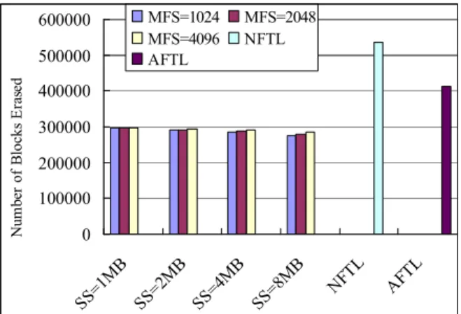
an 20GB NAND flash memory. The block size, the page size, and the size of the spare area of each page were 16KB, 512B, and 16B, respectively, where there were 32 pages per block. The segment size was controlled by a parameter SS. The larger the SS was, the less the number of coarse-grained slots, and the less the memory space to store the coarse-grained translation table (CGTT). Each coarse- grained slot occupied about 28B. The maximum number of fine- grained slots was controlled by a parameter M F S. The larger the M F S value was, the more the memory space to store the fine-grained slots (i.e., the fine-grained translation table). Each fine-grained slot occupied 20B. In the experiments, M F S ranged from 1,024 to 4,096.
B. Main Memory Requirements
!
"# #
$"# #
Fig. 10. Memory Space Requirements
When NFTL (i.e., a block-level address mechanism) was adopted, 10MB of main memory was needed to do address translation for the 20GB flash memory. In the experiments, HFTL just required only 100KB main memory for address translation, and the main memory requirement was adjustable, as shown in Figure 10. When M F S was large, the memory space requirements increased. It was because the size of FGTT increased. When SS was large, the memory space requirements decreased. It was because the number of coarse-grained slots became smaller such that CGTT had a small size. The main memory space requirements were mainly dominated by the size of CGTT, where FGTT was under control with a restricted size. The system performance remains good, compared to NFTL, even when the main memory space requirement was about 100KB.
C. Address Mapping
! ! " ! #
$%Fig. 11. The Number of Pages Read for Address Mapping
1) The Number of Pages Read: The number of pages read was measured for address mapping. As shown in Figure 11, the number of pages read for address mapping of HFTL was less than that of NFTL in most cases. It was because FGTT could provide efficient address mapping, and swapped fine-grained slots could be found in the swap area when needed. When SS was large, the number of pages read of HFTL increased. It was because a large segment could accumulate more swapped fine-grained slots stored in the swap area such that the number of pages read for address mapping could increase. When M F S was large, more address mapping would be satisfied through FGTT such that the number of pages read for address mapping can decrease.
! ! " # $ %
"
"
"
Fig. 12. The Number of Live Pages Written in Swapping Fine-grained Slots
2) The Number of Pages Written: The number of pages written was measured in the swapping of fine-grained slots to flash memory.
As shown in Figure 12, when SS was large, the number of pages written for swapping fine-grained slots decreased. It was because a large segment could provide a better opportunity for fine-grained slots efficiently to describe the address mapping of the segment such that the number of fine-grained slots could be less. When M F S was large, the number of pages written decreased. It was because the large M F S can provide a better opportunity to eliminate the invalid fine-grained slots such that the number of pages written could be less.
D. Garbage Collection Overhead
!
Fig. 13. The Number of Blocks Erased
!"##$%&!
Fig. 14. The Number of Live Pages Written per Erase The number of blocks erased and the number of live pages written per block erase were used to evaluate the garbage collection overhead.
As shown in Figure 13 and 14, HFTL had less blocks erased than NFTL, and the number of live pages written per block erase was also less than that of NFTL. It was because the large segments could postpone garbage collection activities such that more blocks erased were delayed. Furthermore, the priority consideration of the four cases in garbage collection effectively helped in reducing the garbage collection overhead. As a result, the total live pages written by HFTL during the garbage collection was less than that of NFTL.
V. C
ONCLUSIONAn efficient design of a flash translation layer was proposed for huge-capacity flash-memory storage systems, i.e., HF T L. HF T L
is an integrated design with both coarse-grained and fine-grained address translation. Coarse-grained address translation aims at the efficient handling of address mapping for large chunks of data accesses. Fine-grained address translation provides efficient address mapping and a swapping mechanism. The experiments show that HFTL can have good performance, compared to NFTL, even with 100KB main memory in address translation for a 20GB flash storage systems. A garbage collection mechanism is also proposed to reduce the garbage collection overhead. We present four priority orders in handling garbage collection to reduce the overhead. The capability of HFTL was evaluated by a series of experiments under realistic workloads. It shows that HFTL does provide reasonable performance in address mapping and can effectively reduce the garbage collection overhead.
For future research, we should further explore different application characteristics and the designs of super-huge-capacity flash-memory storage systems. More research and tool designs in the customization of flash-memory storage systems for different embedded application systems might prove being very rewarding.
R EFERENCES [1] http://www.samsung.com/Products/Semiconductor/
NANDFlash/index.htm
[2] U.S. Pat. No. 5,937,425 “FLASH FILE SYSTEM OPTIMIZED FOR PAGE- MODE FLASH TECHNOLOGIES”
[3] R. Bez, E. Camerlenghi, A. Modelli, and A. Visconti, “Introduction to Flash Memory,” Proceedings of The IEEE, Vol. 91, No. 4, April 2003.
[4] Samsung Electronics. NAND flash-memory datasheet and SmartMedia data book, 2006.
[5] J. Kim, J. M. Kim, S. H. Noh, S. L. Min, and Y. Cho, “A Space-Efficient Flash Translation Layer for Compact-Flash Systems,” IEEE Transactions on Consumer Electronics, Vol. 48, No. 2, MAY 2002.
[6] Soo-Young Kim and Sung-In Jung, “A Log-based Flash Translation Layer for Large NAND Flash Memory,” ICACT, Feb 2006.
[7] Sang-Won Lee, Won-Kyoung Choi, and Dong-Joo Park, “FAST: An Efficient Flash Trnaslation Layer for Flash Memory,” EUC Workshop 2006.
[8] M. Wu, and W. Zwaenepoel, “eNVy: A Non-Volatile, Main Memory Storage System,” Proceedings of the 6th International Conference on Architectural Support for Programming Languages and Operating Systems (ASPLOS 1994), 1994.
[9] C. H. Wu, T. W. Kuo, and C. L. Yang, 2004, “Energy-Efficient Flash-Memory Storage Systems with Interrupt-Emulation Mechanism,” accepted and to appear in the IEEE/ACM/IFIP International Conference on Hardware/Software Codesign and System Synthesis, Stockholm, Sweden, September, 2004.
[10] A. Kawaguchi, S. Nishioka, and H. Motoda, “A Flash-Memory Based File System,”
USENIX Technical Conference on Unix and Advanced Computing Systems, 1995 .
[11] H. J. Kim and S. G. Lee, “A New Flash Memory Management for Flash Storage System,” Twenty-Third Annual International Computer Software and Applications Conference October 25 - 26, 1999 Phoenix, Arizona.
[12] C. H. Wu, L. P. Chang, and T. W. Kuo, “An Efficient B-Tree Layer for Flash- Memory Storage Systems,” ACM Transactions on Embedded Computing Systems (ACM TECS), Volume 6, Issue 3 (July 2007).
[13] C. H. Wu, L. P. Chang, and T. W. Kuo, “An Efficient R-Tree Implementation over Flash-Memory Storage Systems,” The 11th International Symposium on Advances in Geographic Information Systems (ACM-GIS 2003).
[14] C. H. Wu, T. W. Kuo, and L. P. Chang, “The Design of Efficient Initialization and Crash Recovery for Log-based File Systems over Flash Memory,” ACM Transactions on Storage (ACM TOS), (4): 449-467 (2006).
[15] C. H. Wu, T. W. Kuo, and C.L. Yang, 2006, A Space-Efficient Caching Mechanism for Flash-Memory Address Translation,’ The 9th IEEE International Symposium on Object and Component-oriented Real-time Distributed Computing (ISORC), Gyeongju, Korea, April 24-26, 2006.
[16] C. H. Wu and T. W. Kuo, 2006, An Adaptive Two-Level Management for the
Flash Translation Layer in Embedded Systems, IEEE/ACM 2006 International
Conference on Computer-Aided Design (ICCAD), San Jose, USA, November 5-9,
2006.
計畫成果自評
在這個計畫目標裡,我們想要提出一個針對大容量快閃記憶體 的有效率快閃記憶體轉換層。一個位置對應的機制包括一個大區塊 位置轉換表以及一個分頁位置轉換表,大區塊位置轉換表是針對大 區塊的資料存取,目的是希望可以大幅減少主記憶體使用量;分頁 位置轉換表是提供快速的位置轉換以及一個置換的機制。一個有效 率的垃圾回收機制也會被提出來。此外有效率的毀損復原方法被提 出來針對大容量快閃記憶體儲存系統。最後偵測毀損的方法被提出 來用來避免不適當的系統初始化。 預計完成三個項目,分別是(1) Low main-memory requirements (2) A garbage collection mechanism (3) System initialization and crash recovery。前 面兩項目標的結果已發表在國際會議論文上,而第三個目標在計畫 結束時,也已完成,並結合前面兩項目標的結果將論文投稿至國際 期刊上,目前還在審稿中,因此本計畫報告是以之前發表在國際會 議論文為主。