行政院國家科學委員會專題研究計畫 成果報告
手部扭轉活動之生物力學(3/3)
計畫類別: 個別型計畫 計畫編號: NSC94-2213-E-006-120- 執行期間: 94 年 08 月 01 日至 95 年 07 月 31 日 執行單位: 國立成功大學醫學工程研究所 計畫主持人: 蘇芳慶 共同主持人: 邱浩遠 報告類型: 完整報告 處理方式: 本計畫可公開查詢中 華 民 國 95 年 10 月 12 日
中文摘要
關鍵詞:拇指及手指功能,運動學,動力學,功能性動作,量測工具 手是人體重要的器官之一‚在日常生活中扮演一重要的角色。大部分的手部抓握功能為 拇指-手指間的關係‚比如指握、掌握及指捏或相似的操作功能。許多不同種類的疾病均會導 致失去拇指或手指功能‚其對整個手功能有極大的影響‚甚至會影響我們在日常生活活動及 工作上的表現。 扭轉開門或開罐是一個我們日常生活中常用的功能性動作,然而對於手部關節炎及手 傷後的病人卻是一大挑戰,此外目前並無許多文獻記載對此的研究,也就是目前並無一個合 適的方法或模型去量測手部扭轉活動時手的運動學及動力學的表現。國立成功大學醫工所 的動態分析實驗室及成大醫院的手外科部在手部及上肢的運動學研究上已有很好的經驗及 背景‚因此我們計畫對人體手部在功能性活動上的表現做更深一步的研究。此模型提供一個 客觀的方法來評估精確的運動學及動力學並運用一手部的數學模型來推測關節的作用力及 肌肉或肌腱的受力情形。 此研究分為三大部分實驗‚第一個部份我們發展及設計一個創新的扭轉器模擬日常扭 轉活動,嵌入微小六軸負荷計及扭力計來量測在手部扭轉活動時拇指或手指之施力大小和 總輸出轉矩。第二個部份使用我們所設計的扭轉模擬器配合三維動作分析系統收集20 位正 常受測者扭轉開罐動作,來建立運動學及動力學的資料庫,探討各拇指/食指之施力大小、 貢獻百分比和拇指/食指各關節之協調特性。第三個部份則接續建立一手指的力學模型以計 算手指關節的受力和力矩及預測肌肉韌帶受力的情形,進一步深入了解每一單位指尖施 力,各手指關節的受力和力矩與肌肉受力大小。 基於此量測方法,未來我們將可簡單地衍生我們的研究到其他的功能性活動上。此研究 未來的目標及其臨床的應用為提供建議合適的治療活動和設計居家及職場使用之適當工具 以避免累積性創傷及術後再傷害的發生。英文摘要
Keywords:Finger and thumb function, kinematics, kinetics, functional activities, assessment tool Hand is one of the most major organs in human body and plays an important role in our daily living activities. Most prehensile functions of hand are the thumb-finger relationships, such as grip, grasp, pinch or similar manipulations. Loss of thumb or finger function resulting from different kinds of disorders has a devastating effect on hand function, even has further influences in our daily activities and occupational performances.
Twisting activities such as jar turning and door opening are common functional activities in our daily living. However, it is a big challenge for the patients with arthritis or after hand injuries. Furthermore, there is little evidence of literature investigate this complicated activity. That is, there is no suitable method or model to measure the kinematics and kinetics of the hand during jar turning. The Motion Analysis Lab of Institute of Biomedical Engineering and Hand Surgery Laboratory, National Cheng Kung University has had excellent experiences and achievements in performing static and kinematics analysis of the hand and upper extremity. Therefore, we investigated biomechanical behavior of human hand while performing twisting activity. This model can provide an objective method to assess the precise kinematics and kinetics and predict the joint reaction and muscle/tendon force using a mathematical model.
Three stages will be executed in this study. In the first study, a custom designed twisting device was designed and developed to measure the applied force of the thumb/index finger and total torque output while performing twisting activity using force/torque sensors. In the second part of the study, we investigated the individual contribution of thumb/index finger in jar opening from biomechanical point of view and the posture and coordination of thumb and fingers. It turns out to establish database of kinematics and kinetics from 20 normal subjects using the custom designed twisting device synchronized with computer-based motion analysis system. In the third part, a biomechanical hand model was developed to calculate the joint reaction force and moment and predict the muscle forces for the thumb and index finger.
In the future, it will be easily to extend the investigations to other kinds of functional activities based on this measurement method. The future goal and clinical application of this study will be to suggest appropriate treatment programs and to design suitable tools in our daily living and occupational uses to prevent cumulative and postoperative injuries.
目錄
中文摘要 ... Error! Bookmark not defined.
英文摘要 ... Error! Bookmark not defined.
目錄...III
INTRODUCTION ... Error! Bookmark not defined.
PURPOSES OF THE STUDY ... 1
LITERATURE REVIEWS ... 1
MATERIALS AND METHODS ... 3
Experimental Apparatus ...3
Subjects and Procedures...3
Data analysis ...6
RESULTS AND DISCUSSION...11
Interaction Forces between Thumb and the Jar Lid ...11
Joint Angles during Jar Openin...13
Muscle Forces ...13
Joint constraint forces and moments...15
Comparisons of the Thumb Model ...17
Limitations ...18
Conculsions ...18
REFERENCES... 19
INTRODUCTION
Jar opening/closing activity requires complicated prehensile functions of the hand, and the activity is a common but challenging task in daily living for elder people. This twisting task needs not only powerful strength of the hand and wrist but also adequate range of motion to generate the sufficient torque. The thumb plays a very important role while performing most of the prehensile activities; as a result, the coordination of the thumb and fingers during performing twisting is important. There is no literature to study the individual contribution of the thumb and each finger to overall torque output. Therefore, we investigated the loads of the thumb and digits in jar opening and tried to develop an instrumented jar to measure the overall twisting torque and applied force and moment of each individual digit.
PURPOSES OF THE STUDY
The purpose of this study was set to measure the force and torque of the thumb in jar-opening task by a custom designed jar-like cylinder instrument. First, we developed an innovative device to simulate the twisting activity and measure the overall twisting torque and applied force and moment of the thumb/fingertip using one torque sensor and multi-axis force/torque sensors. Based on this study, we will be able to measure force and moment of thumb or index fingertip and the total twisting torque during the twisting activity. Second, we measured the kinematics and kinetics performances of normal subjects using the custom-design finger load measured device incorporating with the video-based motion analysis system. Main objectives included 1) observation of which position makes maximal force or torque during the activity, 2) analysis of the coordination of three thumb/index finger joints during performing twisting, and 3) ratio of the twisting torque of the thumb/index finger to overall torque output. Third, a three-dimensional biomechanical model describing the detail anatomical structure of the musculotendinous and joint complex of the hand was also be developed to calculate the resultant force and moment of the thumb/index finger joints and predict the muscle forces. Then, this model will be applied in twisting activity to investigate how much the force is generated by the muscle and how the musculoskeletal system keeps the balance and stable in thumb/finger joints. Besides, to discover the torque contribution of the thumb in female adults may also bring the research respect on the potential threat of cumulated trauma disorders in this complicated task.
LITERATURE REVIEWS
Jar opening activity is a common but challenging task in daily living for female adults. Many female adults had trouble in opening the jar with vacuum-sealed lid. The repetitive overload of the thumb in such task may cause a pollex tendon injury. For the patients receiving ligament reconstruction of the thumb, the jar opening was reported as the most difficult task to perform in their daily activity (Rayan & Young, 1997). Usually, in order to overcome the friction resistance of the vacuum-sealed lid, people tend to use the dominant hand to grasp the jar lid firmly and
then turn it counter-clockwise with effort to achieve opening. This twisting task needs not only adequate range of motion but also powerful strength of the hand and wrist to generate the sufficient torque. The thumb plays a very important role in balancing the lid grasp with other digits and leading the lid turning at the same time. There are usually force challenge to complete the tasks and potential threat to acquire tendon injury in performing this twisting activity (Voorbij and Steenbekkers, 2000).
Thumb is usually in charge of providing the opposite force to the other four digits to manipulate various objects in performing daily tasks (Edwards, Buckland, and McCoy-Powlen, 2002). In holding a plate or a cylinder, it is easy to understand that the thumb contributes the same magnitude of force against all the other counter digits together. Therefore, researchers were interesting in discovering the force contribution pattern of the individual fingers in grasping a plate or cylinder (Radwin et al., 1992; Talsania and Kozin, 1998). In jar-opening task, the thumb performs a more complicated pattern including grasping and turning. Firstly, all the digits of the hand make an opposed palmar grasp (Moss & Hogg, 1981) and provide a strong torque to overcome the most friction resistance of the jar lid. When making this opposed palmar grasp, a kind of power grip, on the jar lid, the thumb extends and slightly abducts with flexion in metacarpal joint as well as inter-phalangeal joint. The other four digits firmly keep the metacarpal joints in extension and both inter-phalangeal joints in about 30~45° flexion. The thumb opposes to fingers and grasp jar lid firmly. This power grip makes the whole hand stiff and the palm close to the jar lid so that the extrinsic muscles of the forearm can transmit a strong power and torque across the wrist for turning. After loosing the jar lid, the digits then make a disc grasp (Exner, 2001) to provide a weaker torque but faster turning. When making this disc grasp, a kind of precision grip, on the jar lid, the thumb obviously abducts with slight flexion in metacarpal joint and inter-phalangeal joint. The other four digits loosely keep the metacarpal joints in slight flexion and both inter-phalangeal joints in about 10~30° flexion. Only the pads of all the digits contact the jar lid to turn it. This disc grasp makes the whole hand agilely and the palm apart from the jar lid so that the intrinsic muscles of the hand can contribute a fast turning movement. During the both grips, the thumb not only offers a normal force for grasping jar lid but also leads a tangent force for turning it.
The contribution of the thumb in this functional and complicated task has not been well reported and thus is worth to respect. To investigate the torque contribution of the thumb needs to measure the force that thumb applies on the jar lid and the overall torque generated by the whole hand in turning simultaneously. The researchers investigated the average torque for opening jar of the aged by means of a jar-shaped force meter before (Voorbij and Steenbekkers, 2000). Fowler and Nicol mounted a force transducer into a jar housing to measure the force and moment of the index finger in simulating daily activities including jar opening (Fowler and Nicol, 1999a, 1999b, 2000, 2001, 2002). However, the force and torque contribution of the thumb has not been well reported in these studies. As a result, we planed to do this study for further investigation in hand opening jar activity.
MATERIALS AND METHODS
Experimental Apparatus
A steel jar-like cylinder (66mm diameter; 84mm height) was customed to embrace two sensors inside to measure the force and torque generated by digits and wrist (Figure 1). One six-axis force transducer (Nano-25, ATI Industrial Automation, North Carolina, USA, Fx, Fy = ±111N, Fz=±445N, Tx,Ty,Tz=±2.8N-m)) was mounted in the jar lid to detect the applied force of the thumb during turning movement. One single axis torque cell (TRT-200, Transducer Techniques, Temecula, CA, USA, torque range: ±22.6 Nm) was fitted inside the centre of the cylinder to record the overall torque generated by the hand and wrist. The signals of the force transducer were amplified and transmitted together with those of the torque cell simultaneously through an A/D converter (InstruNet-100, GW Instruments, Somerville, MA, USA) to a computer for recording and analysis. Unlike the regular jar lid, the edge of this lid was rather smooth without any design to promote the friction between thumb and the surface.
Figure 1: Schematic of the jar-like cylinder instrument
Connect the force/torque sensor to the video-based motion analysis system to ensure that it is available to activate these two systems simultaneously: In conjunction with the measurement of the kinetic performance of the thumb, three-dimensional kinematic data acquired using a six-camera motion analysis system (Motion Analysis Corporation, California, USA). A small volume calibration frame will be used to calibrate the accuracy of the system. Eight 20 mm diameter retro-reflective markers are mounted on the calibration frame. Calibration residuals for this system are a measure of its accuracy in recording marker positions. Each motion data collection lasted for 5 seconds at a 60Hz sampling rate. The three-dimensional coordinates of the surface markers were registered and reconstructed. Three dorsal markers on the wrist were used to construct a local hand coordinate system, in which later data was referenced. A MATLAB® program was created to compute kinematical and kinetic data.
Subjects and Procedures
Eight female and two male healthy volunteer (mean ± SD: age, 27.2 ± 5.5 years; mass, 55.4 ± 5.9 kg; height, 158.5 ± 5.2 cm; hand length, 18 ± 0.8 cm; hand width, 8.9 ± 0.4 cm) took part in
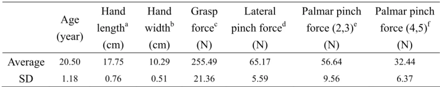
the experimental of the study. The subjects had no history of hand pain or arthritis and were right hand dominant. The hand length was measured from the center of the distal wrist crease to the tip of the long finger in full extension. The hand width was measured from the radial side of the thumb’s metacarpal joint to the ulnar side of the little finger’s metacarpal joint in the full open hand. The grip power was examined by a hydraulic dynamometer (Baseline, Irvington, NY, USA) which was used to measure the maximal strength of the hand in cylindrical grasp. The power of lateral pinch and palmar pinch was examined by a pinch meter (Baseline, Irvington, NY, USA). Table 1 showed the data of the subjects.
Table 1. Average age, hand size and grip power of the subjects Age (year) Hand lengtha (cm) Hand widthb (cm) Grasp forcec (N) Lateral pinch forced (N) Palmar pinch force (2,3)e (N) Palmar pinch force (4,5)f (N) Average 20.50 17.75 10.29 255.49 65.17 56.64 32.44 SD 1.18 0.76 0.51 21.36 5.59 9.56 6.37
a : measured from the center of the distal wrist crease to the tip of the long finger in full extension.
b : measured from the radial side of the thumb’s metacarpal joint to the ulnar side of the little finger’s metacarpal joint in the full open hand.
c : measured by a hydraulic dynamometer to record the maximal strength of the hand in cylindrical grasp.
d : measured by a pinch meter to record the maximal strength of the thumb pad against the radial side of the index.
e : measured by a pinch meter to record the maximal strength of the thumb pad against the pads of the index together with the long finger.
f : measured by a pinch meter to record the maximal strength of the thumb pad against the pads of the ring finger together with the little finger.
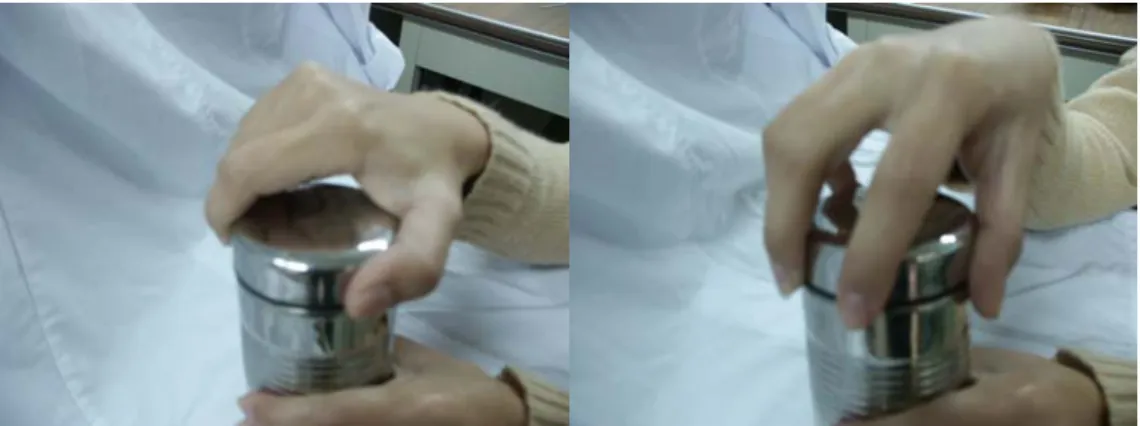
Two measured types of palmar pinch included the thumb to the index together with the middle finger and the thumb to the ring finger together with the little finger, respectively. Each subject was instructed to sit in front of a working table adjusted to the same height as her elbow. In order to prevent from shoulder compensation in making effort opening activity, a restrict belt was wrapped around her both arms close to the trunk. The subject was instructed to use her right hand to perform two types of grip patterns on the jar lid and turn it counter-clockwise as opening task with maximal effort and use the unmarked hand in any comfortable position to grip the base of this jar simulator. Two types of grip patterns included power grip and precision handling on the jar lid (Figure 2). Each subject was asked to keep her maximal effort in counter-clockwise opening for several seconds. The jar was turned at subject’s own preferred speed. The data of force change from beginning to the optimal plateau were all measured. Three trials of jar opening under each condition were recorded and averaged for analysis.
Fiugure 2. Two types of grip patterns (a) The power grip (b) The precision handling
About the marker system for thumb in this study, thirteen 4 mm diameter retro-reflective markers were attached on the dorsal surface of the thumb to define the local coordination system of the thumb and three markers were on the jar simulator to define its coordination system (Figure 3). The 12th and 13th markers were use to define the IP joint center, and then would be removed in trial of opening jars.
In every local coordination system of the thumb, the long axis(x) of every segment was defined as the unit vector form the distal marker to proximal marker of the “T” markers set. The dorsal axis(y) was defined as the unit vector of the cross product of the vector (from the distal marker to third marker of the “T” markers set) and the x axis. The radially directed axis(z) was the cross product of the x and y axis.
Figure 3 Markers setting in neutral position
The subject was asked to sit in front of an experiment table and position the elbow joint in 90 degree. Three-dimensional kinematic data was collected by using a six-camera motion analysis system (ExpertVisionTM3D Motion Analysis system, USA) and the kinetic performance
60 Hz and then the kinematic data were filtered at 5 Hz using a low-pass Butterworth filter further.The procedures and flow charts of this study showed in Figure 4.
Figure 4. The procedures and flow charts of this study Data analysis
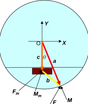
In order to find out the torque contribution of the thumb in jar opening activity, the tangential and radial force components of the thumb to the jar lid must be measured. The coordinate system of the jar-like cylinder and related parameters were defined and shown in Figure 5, where the origin was set on the top centre of the jar lid and the Z-axis was positive upward from side view. The distance between the origin and the point of the applying force was defined as az. The other parameters were defined as following and shown in Figure 5.
θ X Y F c b O M a Mm Fm θ X Y F c b O M a Mm Fm
Figure 5: The coordinate system and parameters defined on the top view over the instrument F: the applied force of the thumb
M: the applied moment of the thumb
Fm: the measured force by the 6-axis transducer Mm: the measured moment by the 6-axis transducer a: the position vector of the applied force
b: the vector from the transducer center to the point of the applied force c: the vector from the origin O to the transducer center
r: the radius of cylinder
θ: the angle between vector c and a on the X-Y plane
The value of az, Mr (radial component of moment M) and θ could be computed by the following equations.
a = [r sinθ, -r cosθ, az]Τ, r = 33mm (1)
c = [0, -11, -10.5] Τ, unit: mm (2)
b = a – c (3)
F = Fm (4)
Mm = M + b × F (5)
Without tensile stress on the circumferential surface of the cylinder, the tangential and axial components of the applied moment M should be zero. The radial direction of the applied moment toward the origin was defined as positive. Then, M can be expressed in terms of Mr as
M = [-Mr sinθ, Mr cosθ, 0]Τ (6)
and Equation (5) can be simplified as a matrix form.
mx r x my r y mz z z sin 33sin cos 33cos 11 0 10.5 M M F M M F M a F
θ
θ
θ
θ
− ⎡ ⎤ ⎡ ⎤ ⎡ ⎤ ⎡ ⎤ ⎢ ⎥ ⎢= ⎥ ⎢+ − + ⎥ ⎢ ⎥× ⎢ ⎥ ⎢ ⎥ ⎢ ⎥ ⎢ ⎥ − + ⎢ ⎥ ⎢ ⎥ ⎢ ⎥ ⎢ ⎥ ⎣ ⎦ ⎣ ⎦ ⎣ ⎦ ⎣ ⎦ (7)transducer and θ can be obtained from the following equation derived from Equation (5):
Mmz = Fy (33sinθ) – Fx (– 33cosθ + 11). (8)
The applied force toward the origin in the radial direction, normal force (Fn), was calculated by using
Fn = – Fx sinθ + Fy cosθ. (9)
And, the tangent component (Ft) of the applied force to the contact point was calculated as
Ft = Fx cosθ + Fy sinθ, (10)
where the counter-clockwise direction was defined as positive. The produced torque Tt of the applied force by the thumb about the cylindrical axis was calculated by.
Tt = r × Ft (11)
The overall twisting torque To was recorded directly by the torque cell in the center of the cylinder. The torque contribution percentage of the thumb was thus defined.
C = (Tt / To) × 100% (12)
In order to compare the difference of the force, torque, and torque contribution between two grip patterns and between two jar positions, nonparametric statistical analyses were used by statistics software (SPSS 10.0, SPSS, Chicago, IL, USA). The correlation coefficient (Pearson’s r) of the hand size and various grip powers to the measured parameters of the thumb in different jar-opening conditions were also calculated to examine their correlation tendency by the same statistics software. The significant levels of both statistics analysis were set as P<0.05.
In order to measure the kinematics data of thumb in jar opening activity, the Eulerian method was used to calculate the joint movements of the joint inthree planes. The first rotation, φ, occurs about the z-axisof the local coordinate system which represents flexion-extension. The secondrotation, θ, about the y-axis represents abduction-adduction. The last rotation, ψ, represents internal and external rotation. The two coordinate systems at the distal and proximal parts of the joint can be transformed following the matrix relationship:
(5)
where c: cosine, s: sine, i, j, k are the unit base vectors along the distal axes of the joint and I, J, K coincide with the axes fixed to the proximal bony segment. Then the individual Eulerian angles of the joint can be determined from the following equations:
θ = -sin-1(i·K )
φ = sin-1(i·J)/cosθ
ψ = sin-1(j·K)/cosθ
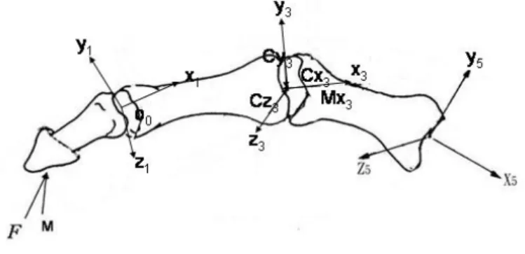
In order to simplify the complex mechanics and muscle coordination of the thumb, it was necessary to assign a mechanical equivalent to each joint to express the thumb structure and function. The IP joint was represented by a hinge joint because it has a bicondylar configuration that permits only flexion-extension. The joint, therefore, has one degree of freedom with three
constraint forces(Cx, Cy, Cz) and two constraint moments(Mx, My). The MCP joint is regarded as a universal joint, and therefore has two degree of freedom with three constraint forces and one constraint moments (Figure 6). The CMC joint is as same as the MCP joint, is regarded as a universal joint.
Figure 6. Three-dimensional forces analysis of the thumb
We utilized the mechanical equilibrium (Σ =F 0, Σ =M 0 at each joint) to solve the muscle and joint constraint forces. The six independent equations were derived for each thumb joint in the static state. Therefore there are total eighteen equilibrium equations at three joints but 21 unknown forces and moments acting about each joint including 8 muscle forces and 13 joint constraint forces and moments (Table 2).
Table 2. Muscle forces and joint constraint forces and moments of thumb
Joint Mechanical
Equivalent
Unknowns Symbolic notation
Interphalangeal Hinge joint Axial compressive force Cx1
Dorsovolar constraint force Cy1
Radio-ulnar constraint force Cz1
Axial moment Mx1
Lateral bending moment My1
Tendon force
Flexor pollicis longus Extensor pollicis longus
FPL EPL
Total 7
Metacarpophalangeal Universal joint Axial compressive force Cx3
Dorsovolar constraint force Cy3
Radio-ulnar constraint force Cz3
Tendon forces: Abductor pollicis brevis
Flexor pollicis brevis Adductor pollicis Extensor pollicis brevis
APB FPB ADP EPB
Total 8
Carometacarpal Universal joint Axial compressive force Cx5
Dorsovolar constraint force Cy5
Radio-ulnar constraint force Cz5
Axial moment Mx5
Tendon forces:
Opponens pollicis Abductor pollicis longus
OPP APL
Total 6
Total number of unknowns 21
The unknowns are more than the numbers of the equilibrium equations. This became a redundant system which makes static analysis indeterminate.
1 1 int
0
(
)
0
n i i i n i i i iFi tendon force vector ei unit vector of Fi
ri position vector of Fi n number of unknown tendon forces at the jo
F applied force vector r position vect
F
F e
C
r
F
F
r
e
M
= = = = = = = =+ Σ
+ =
× + Σ
×
+
=
JJK K JJK K JJK JJK KJK
JK K
JK
K JK
JK K
K
JJK
int int int int
or of F
C=jo constra force vector M=jo constra moment vector
JJK
JK JJK
The optimization technique would be used to solve the problem of the redundant system. The Matlab 6.1 software was used to process the optimal calculation. The objective function
minimizing overall muscle stress was selected. Min
∑
(FiM /PCSA)20 * max M
i PCSA σ
≤F ≤ i = 1, m
σmax=35.3 N/cm2 was the maximum which a thumb muscle could bear.
RESULTS AND DISCUSSION
Interaction Forces between Thumb and the Jar Lid
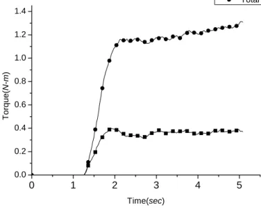
The results of the applied forces of the thumb to the jar lid showed in Table 3. In those two activities, the normal forces applied by the thumb were average about 45N and the tangent forces were average about 15N. The twisting torque contribution of the thumb was average about 32.5%. Figure 7 and 8 showed the thumb forces and torque applied to the jar lid in power grip and precision handling. Table 4 was the external loading data, which the jar lid applied to the thumb, applied to the IP joint with respect to the distal phalanx axis system during the two activities. External moments tended to extend, adduct and internally rotate the IP joint.
0 1 2 3 4 5 0 10 20 30 40 50 Forc e ( N ) Time (sec) Fx Ft Fn
0 1 2 3 4 5 0.0 0.2 0.4 0.6 0.8 1.0 1.2 1.4 Torque( N-m ) Time(sec) Thumb torque Total torque
Figure 7. Power grip: thumb forces and torque to the jar lid.
0 1 2 3 4 5 0 5 10 15 20 25 30 For c e ( N ) time (sec) Fx Ft Fn
0 1 2 3 4 5 0.0 0.2 0.4 0.6 0.8 1.0 1.2 Torque ( N-m ) Time (sec) Thumb torque Total torque
Figure 8. Precision handling: thumb forces and torque to the jar lid. Table 3. Thumb forces applied to the jar lid (standard deviations)
Activity Tangent forces (N) Normal forces (N) Fx (N) Thumb torque (N-m) Total torque (N-m) Thumb contribution (%) Power grip 13.2 (4.9) 46.0 (16.7) 2.5 (4.2) 0.556 (0.203) 1.860 (0.712) 30.1 (6.9%) Precision handling 14.3 (4.9) 42.2 (17.1) 0.7 (6.0) 0.595 (0.190) 1.652 (0.420) 35.2 (5.4%) Table 4. External forces and moments applied to IP joint, with respect to the distal phalanx axis system Activity Fx Fy Fz Mx My Mz Power grip -4.8 (7.5) 45.9 (17.4) 2.2 (4.8) 0.183 (0.153) -0.010 (0.122) -0.603 (0.316) Precision handling 0.8 (6.7) 42.7 (17.3) -6.0 (5.4) 0.202 (0.250) -0.113 (0.079) -0.485 (0.431)
Joint Angles during Jar Opening
The results of each joint angle during jar opening in power grip and precision handling showed in Table 5.The IP joint was flexion and the MCP and CMC joints were extension. The angle of abduction/adduction, MCP and CMC joints positioned in abduction.
Table 5. The results of joint angles (standard deviations) during jar opening (degree)
Power grip
Precision handling
IP flexion
21.0 (11.7)
17.5 (15.3)
MCP extension
11.5 (11.4)
20.6 (11.6)
MCP abduction
8.4 (10.0)
12.7 (12.7)
CMC extension
11.4 (11.4)
9.6 (8.5)
CMC abduction
3.3 (7.4)
4.1 (8.3)
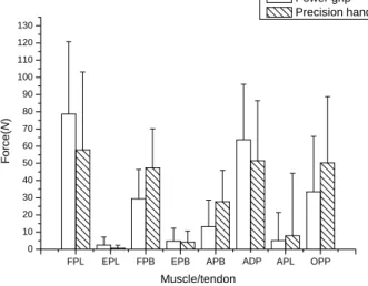
Muscle ForcesThe result of muscle forces of the thumb during jar opening showed in Figure 9. The major active muscles were FPL, FPB, APB, ADP and OPP. The forces of extensor muscles (EPL, EPB, APL) not larger than flexor muscles were average 15N and were about 6 % of total muscle forces. Although the expression of the extensor muscles was not significant, the extensor muscles still made contribution to the joint stability in abduction/adduction direction.
FPL EPL FPB EPB APB ADD APL OPP
0 10 20 30 40 50 60 70 80 90 100 110 120 130 Fo rc e (N ) Muscle/tendon Power grip Precision handling ADP
Figure 9. Average maximum muscle/tendon forces during jar opening
The result of muscle forces per unit external applied forces during jar opening showed in Figure 10. Nonparametric statistical analyses were used to compare the muscles force magnitudes in the two activities. At the condition of one unit external applied forces, it was not significant in the individual muscle forces but was significant in the expression of total muscle forces (p<0.05). Total muscle forces in precision handling were 5.6 times the thumb applied forces and were 4.7 times the thumb applied forces. It meat that power grip was a more effective activity than precision handling.
FPL EPL FPB EPB APB ADD APL OPP 0.0 0.2 0.4 0.6 0.8 1.0 1.2 1.4 1.6 1.8 2.0 2.2 2.4 Force p e r unit ext e rnal ap plied re sult a n t f o rce Muscle Power grip Precision handling * * p<0.05 ADP
Figure 10. Average maximum muscle/tendon forces of the thumb per unit external applied force
Joint Constraint Forces and Moments
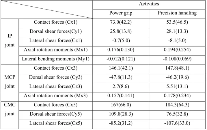
About the results the joint constraint forces and moments of the thumb (Table 6), the external forces and the muscle forces were the major factors to influence the joint constraint forces and moments. At each articular surface, joint bore the contact forces (Cx) mainly. CMC joint bore the largest dorsal and lateral shear forces among three joint.
Table 6. Average maximum joint constraint forces (standard deviations) during jar opening Activities
Power grip Precision handling
Contact forces (Cx1) 73.0(42.2) 53.5(46.5)
Dorsal shear forces(Cy1) 25.8(13.8) 28.1(13.3)
Lateral shear forces(Cz1) -0.7(5.0) -8.1(5.0)
Axial rotation moments (Mx1) 0.176(0.130) 0.194(0.254)
IP joint
Lateral bending moments (My1) -0.012(0.121) -0.108(0.069)
Contact forces (Cx3) 146.1(42.1) 147.8(48.1)
Dorsal shear forces (Cy3) -47.8(11.3) -46.2(19.6)
Lateral shear forces(Cz3) 2.7(8.6) 5.51(13.1)
MCP joint
Axial rotation moments (Mx3) 0.157(0.141) 0.178(0.234)
Contact forces (Cx5) 167(66.0) 184.3(64.3)
Dorsal shear forces(Cy5) 109.8(28.3) 76.5(32.8)
CMC joint
Axial rotation moments (Mx5) -0.114(0.432) -0.137(0.492) Unit: constraint force(N), constraint moment(N-m)
Figure 11 was the joint resultant forces per unit external applied forces during jar opening. The joint resultant forces at CMC, MCP and IP joint were 4.8, 3.3 and 1.5 times the thumb applied forces respectively.
IP MCP CMC 0 1 2 3 4 5 6 7
Force per uni
t e x tern al ap plie d resultant f o rce Joint Power grip Precision handling
Figure 11. Joint resultant forces of the thumb per unit external applied force
At the condition of one external applied force, the lateral shear force was significant higher in precision handling (Table 7). This suggested that because the direction of turning was as same as the direction that muscle forces applied in power grip, the muscle applied less force to resist the external lateral forces and then reduced the joint resultant forces.
Table 7. Joint constraint forces of the thumb per unit external applied force Activities
Power grip Precision handling
Contact forces (Cx1) 1.40(0.72) 1.17(0.74)
Dorsal shear forces(Cy1) 0.57(0.16) 0.64(0.19)
Lateral shear forces(Cz1) * 0(0.08) -0.19(0.12)
Axial rotation moments (Mx1) 0.004(0.003) 0.004(0.004)
IP joint
Lateral bending moments * (My1) 0(0.002) -0.003(0.002)
Contact forces (Cx3) 3.01(0.72) 3.50(1.09)
Dorsal shear forces(Cy3) -1.00(0.27) -1.11(0.55)
MCP joint
Axial rotation moments (Mx3) 0.003(0.003) 0.004(0.004)
Contact forces (Cx5) 3.46(0.73) 4.28(1.34)
Dorsal shear forces(Cy5) 2.38(0.46) 1.79(0.64)
Lateral shear forces(Cz5) * -1.68(0.28) -2.52(0.69)
CMC joint
Axial rotation moments (Mx5) -0.001(0.008) -0.005(0.011)
* p<0.05
Comparisons of the Thumb Model
We also compared our results to other thumb models of previous studies. Table 8 was the comparisons of the thumb model. Cooney et al. (1977) used the three-link model but Giurintano et al. (1995) used the five-link model to predict the muscle and joint loads of the thumb in ADLs. Giurintano et al. considered that the flexion-extension axis should not perpendicular to the abduction-adduction axis at the MCP and CMC joint. The biomechanical model of the thumb developed by Cooney et al. assumed that the extensor-muscle forces were excluded and that FPB and OPP acted as one force vector. Therefore, the muscle and joint loads of the thumb would be solved from a static determinate system. The moment arm of individual muscle was measured by Cooney et al. and Giurintano et al. from X-ray or CT images. In this study, the moment arm of muscles we used was measured by Smutz et al. It would cause the different moment arm of muscles because of the different measuring tools and then affected the muscle loads.
Table 8. Comparisons of thumb model
Cooney et al.(1977) Giurintano et al.(1995) This study
Models Three-link model Five-link model Three-link model
Input force Assumed value Assumed value Measured value
Methods Inverse dynamics;
statically determinate Inverse dynamics; statically indeterminate; (Objective Function: 2 i σ Σ ) Inverse dynamics; statically indeterminate; (Objective Function: 2 i σ Σ ) Assumption of the muscles (1) EPL, EPBwere eliminated
(2)FPB & OPP act as one force vector
During grip activities,they assumed
FPL, FPB, APL, APB were not the main muscle to stable the thumb joints
All 8 muscles are considered in our equations
Muscles constraints
f muscle > 0 f muscle > 0 f muscle_max>f muscle > 0 Moment arm of
the thumb muscles
Biplanar roentgenograms
CT images Assumed value
(Smutz et al.)
Limitations
There were some limitations in this study. Previous researchers had measured the physiological cross-section area and the moment arm of individual muscle of the thumb but those were measured form cadavers. The parameters used in the biomechanical model would affect the prediction of muscle and joint forces. In order to simplify the complex anatomy and function of the joints and muscles, some of the assumptions might exist. The assumption that joint axial forces should be compressive and the maximal muscle force should not be larger than it could bear physiologically was still adequate. The resultant forces were assumed to pass the joint center but actually the contact point between joints would be more than one point. This assumption, therefore, would cause the additional moments to the joints.
Conclusions
During jar opening, the average total muscle forces were 240.7N (the major active muscles were FPL=67.5N, FPB=38.9N, APB=20.5N, ADP=58.5N, OPP=37.3N). The activity of precision handling needed the large muscle forces than the activity of power grip for each one unit external force applied to the thumb. This meant “precision handling” was more energy cost than “power grip”. According to our thumb model, it bore 221.5N at the carpometacarpal (CMC) joint, about 4.8 times the apply forces of the thumb, 153N at he metacarpophalangeal (MCP) joint, about 3.3 times the apply forces of the thumb and 69N at the interphalangeal (IP) joint, about 1.5 times the apply forces of the thumb.
The new apparatus presented here provides a proper method for measuring the three dimensional load during the activities, and then using the three dimension analysis would provide more knowledge about the muscle and joint load. This study contributed to the measurement of the biomechanical express and prediction of the muscle and joint loads of the thumb during the activities of jar opening.
REFERENCES
何昆岳,開罐動作之拇指生物力學分析,國立成功大學醫學工程研究所碩士論文,2004。 Adams, J.P., Borenstein, D.G., Feffer, H.L., Wiesel, S.W., 1987. Hand and Wrist Pain. The Michie
Company, Charlottesville, Virginia.
Burstedt, M.K.O., Flanagan, J.R., Johansson, R.S., 1999. Control of grasp stability in humans under different frictional conditions during multidigit manipulation. J. Neurophysiol. 82(5), 2393-2405.
Edwards, S.J., Buckland, D.J., McCoy-Powlen, J.D., 2002. Developmental & Functional Hands Grasps. SLACK Incorporated, Thorofare, NJ, USA.
Exner, C.E., Occupational Therapy for Children, 4th ed. Development of hand skills, Case-Smith, J., Allen, A.S., Pratt, MO: Mosby-Year Book Inc., P.N. St. Louis, 289-328.
Fowler, N.K., Nicol, A.C., 1999. A force transducer to measure individual finger loads during activities of daily living. J. Biomech. 32, 721-725.
Fowler, N.K., Nicol, A.C., 1999. Measurement of external three-dimensional interpersonal loads applied during activities of daily living. Clin. Biomech. 14, 646-652.
Fowler, N.K., Nicol, A.C., 2000. Interphalangeal joint and tendon forces: normal model and biomechanical consequences of surgical reconstruction. J. Biomech. 33, 1055-1062.
Fowler, N.K., Nicol, A.C., 2001. Functional and biomechanical assessment of the normal and rheunatoid hand. Clin. Biomech. 16, 660-666.
Fowler, N.K., Nicol, A.C., 2002. A biomechanical analysis of the rheumatoid index finger after joint arthroplasty. Clin. Biomech. 17, 400-405.
Johanson, M.E., Valero-Cuevas, F.J., Hentz, V.R., 2001. Activation patterns of the thumb muscles during stable and unstable pinch tasks. J. Hand. Surg. 26, 698-705.
Johansson, R.S., Hager, C., Riso, R., Backstrom, L., 1992a. Somatosensory control of precesion grip during unpredictable pulling loads. I. Changes in load force amplitude. Exp. Brain. Res. 89, 181-191.
Johansson, R.S., Hager, C., Riso, R., Backstrom, L., 1992b. Somatosensory control of precesion grip during unpredictable pulling loads. II. Changes in load force rate. Exp. Brain. Res. 89, 192-203.
Kuo, L.C., Su, F.C., Chiu, H.Y., Yu, C.Y., 2002. Feasibility of using a video-based motion analysis system for measuring thumb kinematics. J. Biomech. 35, 1499-1506.
Kuo, L.C., Cooney, W.P. III., Oyama, M., Kaufman, K.R., Su, F.C., An, K.N., 2003. Feasibility of using surface markers for assessing motion of the thumb trapeziometacarpal joint. Clin. Biomech. 18, 558-563.
Li, Z.-M., 2002. Inter-digit co-ordination and object-digit interaction when holding an object with five digits. Ergonomics 45(6), 425-440.
Miller, M.C., Nair, M., Baratz, M.E., 2005. A device for assessment of hand and wrist coronal plane strength. J. Biomech. Eng. 127, 998-1000.
Moss, S.C., Hogg, J., 1981. Frontiers of knowledge in mental retardation. Developmental of hand function in mentally handicapped and nonhandicapped preschool children. MD: University
Park Press., Mittler. Baltimore, 35-44.
Olafsdottir, H., Zatsiorsky, V.M., Latash, M.L., 2005. Is the thumb a fifth finger? A study of digit interaction during force production tasks. Exp. Brain. Res. 160(2), 203-213.
Radwin, R.G., & Oh, S., 1992. External finger forces in submaximal five-finger static pinch prehension. Ergonomics 35(3), 275-288.
Rayan, G.M., Young, B.T., 1997. Ligament reconstruction arthroplasty for trapeziometacarpal arthrosis. J. Hand. Surg. [Am]. 22, 1067-1076.
Talsania, J.S., Kozin, S.H., 1998. Normal digital contribution to grip strength assessed by a computerized digital dynamometer. J. Hand. Surg. [Br]. 23B, 162-166.
Voorbij, A.I.M., Steenbekkers, L.P.A., 2002. The twisting force of aged consumers when opening a jar. Appl. Ergon. 33, 105-109.
SELF EVALUATION
The overall goal of the project is to develop a scientific and objective measurement method of functional performances of hand during twisting activity. In the first year study, we have completed the innovative device system to simulate the twisting activity and tested the feasibility and accuracy of this device. In the second year study, we have used this device to measure the overall twisting torque and applied force and moment of the thumb/fingertip using one torque sensor and multi-axis force/torque sensors, and then used this device and motion analysis system to collect the kinetics and kinematics data of thumb simultaneously during jar opening. We also tested the reliability of the system while collecting the kinematical and kinetic data and tried to establish the kinematical and kinetic database of the thumb and hand of the jar turning activity. In addition to comparing two different postures, we tried to investigate which posture of the hand produce the maximum twisting torque. In the third year of study, we developed an inverse dynamic model to calculate joint reaction forces and moment of DIP, PIP and MP joint during the jar turning activity and establish an optimization muscle model to predict muscle/tendon during the jar turning activity. This biomechanical model of the thumb showed us how the musculoskeletal system keeps the balance and stable in each thumb joint.
Although there were limited subjects, the findings suggested the particularity of the twisting activity, which cannot be measured by general dynamometer and pinch meter in clinic. Participated persons trained from this project in how to design a device and use the motion analysis system in measuring the kinematical and kinetic of the hand and also learned the functional anatomy and biomechanics of hand movements.
In this study, we not only obtained the motion and kinetic database of normal subjects, but also effectively offered for the clinic applications in providing objective progressive evaluation and designing the rehabilitation programs and appropriate tools for occupational and house uses.