行政院國家科學委員會專題研究計畫 成果報告
輪型自走式雙臂仿人型機器人系統之研發 研究成果報告(精簡版)
計 畫 類 別 : 個別型
計 畫 編 號 : NSC 98-2221-E-011-079-
執 行 期 間 : 98 年 08 月 01 日至 99 年 07 月 31 日 執 行 單 位 : 國立臺灣科技大學機械工程系
計 畫 主 持 人 : 黃緒哲
計畫參與人員: 碩士班研究生-兼任助理人員:&;#63943;軒 碩士班研究生-兼任助理人員:吳俊錫
報 告 附 件 : 出席國際會議研究心得報告及發表論文
處 理 方 式 : 本計畫可公開查詢
中 華 民 國 99 年 09 月 16 日
行政院國家科學委員會專題研究計畫 成果報告
輪型自走式雙臂仿人型機器人系統之研發
計畫類別: 個別型計畫
計畫編號: NSC98-2221-E-011-079-
執行期間: 98 年 08 月01 日至 99 年 07 月31 日 執行單位: 國立臺灣科技大學機械工程系(所)
計畫主持人: 黃緒哲 計畫參與人員: 劉軒,吳俊錫
報告類型: 完整報告
處理方式: 本計畫可公開查詢
中 華 民 國 99 年 9 月 10 日
行政院國家科學委員會補助專題研究計畫
■ 成 果 報 告□期中進度報告
輪型自走式雙臂仿人型機器人系統之研發
計畫類別:■ 個別型計畫 □ 整合型計畫 計畫編號:NSC 98-2221-E-011-079-
執行期間: 98 年 8 月 1 日至 99 年 7 月 31 日
計畫主持人:黃緒哲教授
計畫參與人員:劉 軒, 吳俊錫
成果報告類型(依經費核定清單規定繳交):□精簡報告 ■完整報告
本成果報告包括以下應繳交之附件:
□赴國外出差或研習心得報告一份
□赴大陸地區出差或研習心得報告一份
■出席國際學術會議心得報告及發表之論文各一份
□國際合作研究計畫國外研究報告書一份
處理方式:除產學合作研究計畫、提升產業技術及人才培育研究計畫、
列管計畫及下列情形者外,得立即公開查詢
□涉及專利或其他智慧財產權,□一年□二年後可公開查詢
執行單位:國立台灣科技大學 機械系(所)
中 華 民 國 99 年 9 月 10 日
輪型自走式雙臂仿人型機器人系統之研發
計劃編號:NSC 98-2221-E-011-079-執行期限:98 年 8 月 1 日到 99 年 7 月31 日 主持人:黃緒哲教授 國立台灣科技大學機械工程系(所)
計畫參與人員:劉 軒, 吳俊錫 國立台灣科技大學機械工程系(所) 一、中文摘要
本研究計畫之目標在自行設計製作 一台具有雙臂人型機器人且具有可移動 之四輪平台的仿人型機器人系統,並利 用Altera Nios II之SOPC發展版來規劃 on-board控制架構,搭配自製驅動器與硬 體電路設計,再整合個人實驗室多年發 展之智慧型控制系統,以實現可在平面 上自由移動之整合性輪式仿人型機器人 系統之軟硬體控制架構。
本年度目標為達成平行運算、增加 系統效能並繼承實驗室已有研究成果,
本研究實驗機台整體架構(圖 1.1)區分 為視覺系統及運動控制系統兩部份。視 覺系統以德州儀器(Texas Instrument, TI)所推出的 TMS320C6416T DSK 做為 運 算 平 台 並 輔 以 原 相 科 技 ( PixArt Imaging Inc, PixArt)所生產之 PAS6311 CMOS VGA DIGITAL IMAGE SENSOR 作為影像感測元件。運動控制系統則使 用美國 Altera 公司所推出的 Nios II Development Kit Stratix II 2S60 RoHS 來 建構控制機械手臂之平台,透過 UART 傳輸介面做為兩者之溝通管道。利用分 散式架構來獨立運作視覺與運動控制系 統之好處在於能以近乎平行處理式架構 以增加整體系統效能,同時可分別選定 適合該系統之運算平台,並可單獨視為 一獨立系統來開發,具模組化及替換性 之優點使系統架構具有彈性。
視覺系統方面選擇 TI 所開發之高 效能 C6000 系列中之 C64x 平台,可提
供高達 1GHz 的運算時脈以配合主體影 像處理演算法需大量演算之需求,可提 高運算速度,運動控制系統方面則考慮 機台發展性及包含雙手臂以及移動平台 部份之高自由度,選用 Altera Stratix II 2S60 RoHS 做為核心,具有 718 個 I/O 腳 位 及 2544192 RAM bits , 並 使 用 Verilog 設計規劃硬體模組包含 PWM、
Decoder 等以配合系統所需功能。
圖 1.1 實驗機台整體架構 關鍵字:立體視覺、視差圖、移動式機 器人、雙臂仿人型機器人、物體偵測
二、前言
機器人從最初應用於工業組裝生產 之作業,隨著感測元件技術、機器人技 術和各種控制理論的發展,機器人之研 究與應用開始蓬勃發展,其中又以仿人 型機器人為智慧型機器人領域中最活躍 的研究焦點,近年來在機器人機構設計
1
與運動控制系統架構及控制理論等領域 已有不少研究成果,然而與環境互動之 功能則還不斷的被研究探討,原因在於 若要與環境互動則必須整合各種感測系 統並使用各種技術對環境進行辨認或偵 測,然而現在普遍使用的紅外線或超音 波等感測器皆有諸多限制,若要讓機器 人具有一定適應性,而又無法限定環境 有特定條件或物體,因此如同人類一般 利用視覺做為感測系統是智慧型仿人型 機器人必須要走的路。
三、研究目的
本研究目的,在希望能繼承實驗室現 有研究成果,以 DSP 做為影像平台之立體 視覺系統與機械手臂運動控制軌跡規劃 及控制理論整合,並加入移動式機器人概 念,以 FPGA 做為運動控制平台,發展一 將機器視覺應用於移動式仿人型雙臂機 器人系統,以 Nios II 發展板為核心,分 成兩部份設計,第一部分是在 FPGA 晶 片內以硬體方式(PLD)實現馬達光學 編碼訊號處理、脈波寬度調變、影像訊 號擷取等主要功能。第二部份是在 Nios II 微處理器內實現反運動學計算、控制 理論、點對點運動控制及數位影像處理 等功能。
四、文獻探討
仿人型及輪型機器人的技術發展與 應用近年來是非常熱門的議題,許多相關 的研究也陸續被提出,而這類機器人的目 的在於取代人力從事一些較危險、粗重的 工作,與人類達到互動的功能,進而減少 人為疏失並降低生產成本,甚至更可提高 精度上的準確性。文獻【1】中提出對一 具有雙臂之輪型機器人的阻抗控制,以達 到此機器人能夠與人類共同持取一物 體,並移動到一固定位置放置的目的;而
文獻【2-6】也提出了一些雙臂機器人的設 計方法、控制策略及其應用,其中包含了 如何讓雙臂機器人作動起來更像人類的 動作、完成更精確的組立任務,並考慮以 分散控制的方式來降低中央主控系統資 源的使用,達到較佳的即時性能,以滿足 雙臂機器人的工作需求。
由於機械手臂的回授控制訊號來自 各關節的旋轉角度,而其應用端為終端器 之空間位置,所以必須搭配反運動學之推 導來配合控制器運作。文獻【7,8】說明 機械手臂機構運動學推導方式,第一種方 式,是根據終端器相對於基座座標為基 礎,藉由乘上反矩陣的方式來推導獲得反 運動學方程式。此方式並未限制終端器方 向而自由度較高,但計算過程較為複雜,
空間座標解析解最多將有四組;第二種方 式,是藉由固定終端器和基座座標的相對 方向來簡化推導過程。此方式可設計終端 器與基座座標永遠保持一相對方向關 係,節省計算時間,空間座標解析解只有 一組。
仿人型機器人之載台移動性,目前可 分為多足型,雙腳型與輪子驅動型,各有 其優缺點多足型可適應出造凹凸上平路 面之移動,為機構交複雜以及所佔投影面 積較大,雙腳型最接近仿人機器人外觀,
惟控制難度與進入門檻高,亦上適用於過 於凹凸上平之路面,輪型架構最簡單,惟 上適用於凹凸上平之路面。
五、系統架構
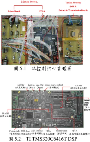
本研究的整體系統架構圖如圖1.1 所示,實體圖如圖5.1所示,影像處理系 統 採 用 TI TMS320C6416T DSK(DSP Starter Kit)(圖5.2)處理器,其運算速 度可達1GHz之定點運算,控制程式透過 開 發 軟 體 Code Composer Studio 3.1
(CCS)進行編譯,使用者可透過C語 言、線性組合語言(Linear assembly)或 組合語言進行程式撰寫。
2
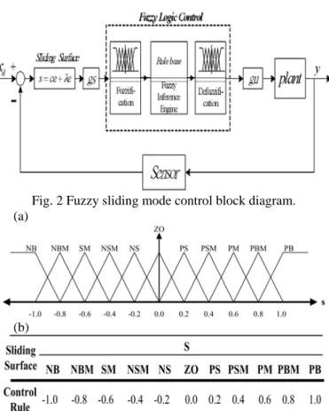
圖 5.1 統控制核心實體圖
圖 5.2 TI TMS320C6416T DSP 使用影像感測器類型為CMOS(互 補 金 屬 氧 化 半 導 體 , Complementary Metal-Oxide-Semiconductor ) 影 像 感 測 器 , 與 CCD ( 電 荷 耦 合 元 件 , Charge-Coupled Devices)影像感測器相 比(如表2.1),具有體積小、成本低、
反應速度快、與半導體製程相容、耗電 量低等優點。選用CMOS為原相科技所 生 產 的 PAS6311 CMOS DIGITAL IMAGE SENSOR,可擷取彩色影像並以 10-bits parallel RGB raw data格式輸出,
具有VGA等級解析度(640x480)約為 30萬畫素,使用I2C介面對CMOS做硬體 設定控制,詳細規格如表5.1所示。
在運動控制運算平台選用上為符合 雙機械手臂與移動平台之高自由度需
求,本研究使用美商 Altera 公司針對 SOPC 設計之 Nios II Development Kit Stratix II 2S60 RoHS 處理器為控制核心
(如圖 5.3)。利用廠商提供的 SOPC Builder 軟體套件,讓使用者可以很快速 的將硬體系統(包括微處理器、記憶體、
周邊介面電路及使用者自訂之邏輯電 路)燒錄到單一個可規劃晶片中,來達 到整個系統的積體設計。Stratix II 系列 做 為 機 台 運 動 控 制 的 核 心 , 其 具 有 60,440 個邏輯單元(Logic Element;
LE )、 最 多 可 用 718 個 I/O 腳 位 及 2544192 RAM bits。此晶片可嵌入一顆 Nios II 處理器,其為 16/32 位元 RISC 架 構且能規劃其核心大小,並提供微處理 器與周邊元件之軟體核心。詳細規格與 細部元件請參考【9】。
表 5.1 PAS6311 CMOS Sensor 規格
3
圖 5.3 Altera Nios II Development Kit 為配合本研究之實驗所需以及未來 發展性,設計製作一全新高自由度雙臂 機器人並搭配輪式移動平台底增加機器 人之靈活性(如圖 5.4)。全新設計之雙 臂機器人擁有單臂五個自由度(如圖 5.5
)不含末端夾爪,比原有機台多出兩個 自由度,使得雙臂能做交互之動作增加 自由度與使用性,在馬達選用上也特別 選取符合手臂各軸大小且扭力足夠之直 流伺服馬達,使肩部負擔減輕。末端夾 爪部份於設計時加入一簡易連桿使得兩 邊夾爪(如圖 5.6)使用單顆馬達便可同 時作動,增加夾爪之開口大小並節省驅 動器之使用。
圖 5.4 輪型移動式雙臂機器人實體圖
圖 5.5 單臂五軸機械手臂 3D 設計圖
圖 5.6 新舊型末端夾爪比較圖 由於包含雙臂機器人、視覺模組及控制 核心等部份已有不輕之重量,在移動平 台上的設計重點著重於輕量化與堅固性
,因為捨棄較複雜之傳統四連桿轉向機 構,另外考量到負載後之堅固性與耐用 性,亦不使用三輪式底盤,改為無轉向 機構之四輪驅動設計,由於四輪驅動式 底盤轉向必需依靠左右兩邊同時正、反 轉進行又右、左旋動作,為方便運動學 推導簡化,故將四輪中心設計為一等邊 矩形(正方形),在不考慮輪胎打滑所產 生之滑動及空轉等等因素下,可假設其 旋轉中心於移動平台之正中心(2D 設計 圖如圖 5.7,實體圖如圖 5.8 所示),其 左、右旋運動方程式可推導出如下:
4
:輪胎中心軌跡
:移動平台初始姿態
:移動平台終點姿態 90° s
y x :輪胎
假設:
假設:
D:輪胎直徑(cm):輪胎直徑(cm),,
D L:輪距=軸
距(cm)
θ:輪胎旋轉度數相對於車身中心 旋轉角度比例
S :輪胎行走距離(90°扇形邊長)
相對於車身中心旋轉角度(cm/°)
D :輪胎旋轉度數相對於輪胎周長d
(cm/°)
90
4 /
1 L
S = π ,
⇒
= D/360 Dd π
L D S Dd = θ =
即當右邊輪胎往負 y 方向、左邊輪 胎往正 y 方向旋轉一度時,相當於車身 中心旋轉θ度。
實際上由於移動平台上架設之雙臂機器 人與控制核心等物體後之重量影響加上 移動速度並不快,因此輪胎鮮少發生打 滑現象,經由後續實驗部份亦證明此推 導方式正確無誤。
圖 5.7 移動平台 2D 設計圖
圖 5.8 移動平台實體圖
六、結果與討論
本研究於第一年度使用系統晶片實 現移動式仿人型機器人影像伺服系統,
以下分別進行多項實驗以驗證本文所設 計架構之正確性。在單機械臂機器人運 動方面,使用相對型 FSMC 作為控制器 並觀察其性能與優缺點。
本章節之運動控制實驗以各軸步階 響應與空間多軸同動實驗點對點運動實 驗,多軸同動實驗起始點從(345, 0, -200)移動至結束點(150, 200, -200,
各軸運動角度如表 6.1 所示。
表 6.1 相對型 FSMC 點對點實驗
Maximum Velocity(deg/s)
40
Maximum Acceleration(deg/s2)
40
J1 J2 J3 J4 Initial Point(mm)
(345, 0, -200) 0.0 0.0 0.0 0.0 Destination
Point(mm) (150, 200, -200)
53.13 44.36 90 97.13
Maximum Actual
Velocity(deg/s) 21 17 41 39
Maximum Position
Error(deg) 0.02 0.02 0.03 0.03
5
圖 6.1 相對型 FSMC 各軸步階響應
圖 6.2 相對型 FSMC 各軸步階響應 控制量
Joint 1 Joint 2
Joint 4 Joint 3
Joint 1 Joint 2
Joint 4 Joint 3
Joint 5
圖 6.3 FSMC 各軸步階響應之誤差
Joint 5
Joint 1 Joint 2
Joint 4 Joint 3
圖6.4 FSMC梯形速度軌跡規劃之空間 運動路徑
Joint 5
圖6.5 FSMC梯形速度軌跡規劃各軸控
6
制量
圖 6.6 FSMC 梯形速度軌跡規劃各軸誤 差
實驗結果如圖 6.1~6.6 所示,各軸最 大 誤 差 量 與 速 度 數 據 整 理 如 表 7.12~7.13,相對型 FSMC 各軸最大誤差
在 內,終端器空間座標最大誤差
在 內,系統性能上可由各軸誤差
以及終端器誤差可發現,相對型 FSMC 在誤差、速度控制與控制量輸出皆有很 好的效果,終端器座標與各軸誤差統整 如表 7.2~7.3。
±0.05° 0.2mm
±
表 7.2 終端器終點座標誤差
終端器終點空間座標誤差(mm)
X Y Z 0.0459 0.0175 0.0424
表 7.3 終端器各軸誤差
終點各軸角度誤差(deg)
Joint 1 Joint 2 Joint 3 Joint 4 -0.0200 -0.0200 -0.0200 -0.0200
軌跡追蹤運動控制實驗設計上規劃 一段直線軌跡讓機械手臂進行追蹤,直 線軌跡從起始點(275, 200, -200)移動 到結束點(75, 200, -200),實驗結果如 圖 6.7~7.10 所示,由圖 6.7 看出由於直 線追蹤一開始由於速度由零一瞬間加速 使得開始一小段時間誤差較大,之後當 控制量追上後控制效果依然良好,可從 圖 7.10 出大部份誤差皆產生於 Joint 4,
再看圖 7.25 Joint 4 的開始速度過大,超 越驅動器的最大加速度,因此造成開始 誤差無法追上,解決此問題可由降低軌 跡追蹤速度,即利用更多點來描述此軌 跡,使得控制器在欲追蹤軌跡點與軌跡 點間之距離變近,使得不需要那麼大的 速度/加速度來追蹤下一點,另外使用上 節實驗之 T-Curve 速度規劃軌跡則不會 發生此現象。
圖 6.7 FSMC 軌跡追蹤之空間運動路 徑
圖 6.8 FSMC 軌跡追蹤之各軸響應
7
圖 6.9 FSMC 軌跡追蹤之控制量
圖 6.10 FSMC 軌跡追蹤之各軸誤差
表 6.4 終端器終點座標與各軸誤差
終端器終點空間座標 誤差(mm)
終點各軸角度誤差 (deg)
X Y Z J1 J2 J3 J4
0.3906 -0.0203 0.0151 -0.1 -0.03 <0.01 -0.05
表 6.5 終端器終點空間座標與各軸最 大誤差
終端器空間座標最大 誤差(mm)
各軸角度最大誤差 (deg)
X Y Z J1 J2 J3 J4
-1.5326 -1.1735 -1.3476 -0.1 0.75 -0.02 2.48
七、參考文獻
【1】 Kazuhiro Kosuge, Hiromu Kakuya, and Yasuhiza Hirata,
“Control Algorithm of Dual Arms
Mobile Robot for Cooperative Works with Human,” IEEE.
0-7803-77-2/01, pp. 3223-3228, 2001.
【2】 ChanHun Park, YoungDong Son, DooHyung Kim, KyoungTaik Park, YoonSung Shin, and
HeeSeoK Ahn, “Design and Control of Dual Arm Robot Manipulator for Precision Assembly,”
International Conference on Control, Automation and Systems 2007, pp. 1140-1143, Oct. 17-
【3】 Kenji INOUE, Yusuke NISHIHAMA, Tatsuo ARAI and Yasushi MAE, “Mobile
Manipulation of Humanoid Robots - Body and Leg Control for Dual Arm Manipulation - ,”
Proceedings of the 2002 IEEE International Conference on Robotics & Automation, pp.
2259-2264, May 2002.
【4】 Cao Qixin, Member, IEEE, Zhang Zhen, Student, IEEE, Gu Jiajun,
“A Distributed Control
and Simulation System for Dual Arm Mobile Robot,” Proceedings of the 2007 IEEE
International Symposium on Computational Intelligence in Robotics and Automation, pp.
450-455, June 20-23, 2007.
【5】 ng HUANG, Junyao GAO, and Weimin ZHANG, “Manipulability and
Stability of Pushing Operation by Humanoid Robot BHR-2,”
Proceedings of the 2007 IEEE International Conference on Robotics and Biomimetics, pp.
751-756, December 15-18, 2007.
【6】 Tao XIAO, QiaTakefumi OSONE, Junya TATSUNO, Tomofumi NISHIDA, and Hisato
8
KOBAYASHI,
“Cooperative Motion Planning for Dual Arm Robot to Demonstrate Human Arm Movements,”
Proceedings of the 2002 IEEE Int.
Workshop on Robot and Human Interactive Communication, pp. 488-493, Sept. 25-27, 2002.
【7】 喬執中, “力量控制於機械手臂 運動之應用," 碩士論文, 國立 中央大學機械工程研究所, 2001.
【8】 L. W. Tsai, “Robot Analysis - The Mechanics of Serial and Parallel Manipulators,” John
Wiley & Sons, Inc., 1999.
【9】 ALTERA, “Altera Embedded
Peripherals,” ALTERA Corporation, 2005.
9
國科會研究計畫出席國際研討會報告 研討會名稱:
ESDA 2010
ASME, 10
thBiennial Conference on Engineering Systems Design and Analysis
12- 14 July, 2010
Istanbul, Turkey, (Yeditepe University)
所發表之論文:
LuGre Friction Model Based Adaptive Control with Functional Approximation Compensation for a Piezoelectric Actuating Table, 作者:
Shiuh-Jer Huang, Su-Hai Hsiang and Kuan-Lian Her and
Gain Scheduling Fuzzy Sliding Mode Strategy for Robotic Motion Control, 作者: Shiuh-Jer Huang, Shian-Shin Wu and You-Min Huang
報 告 人 黃 緒 哲 教 授
國立台灣科技大學機械工程系
此次參加 ESDA2010 ASME 第十屆工程系統設計與分析國際學 術研討會,此研討會為中型研討會,每兩年舉行一次,今年在土耳其 伊斯坦堡 (Istanbul) 城市郊區之 Yeditepe University 校園內舉辦,參 與人數與投稿論文篇數眾多,共有 568 篇論文核准發表,分成 15 個 專業領域,涵蓋機械方面之所有相關研究領域,並在研討會之三天內 分成十個不同領域與主題 Session 同時進行,研討會中間大會有邀請 來自他國之五個傑出教授提供五場 keynote lectures。此次研討會屬於 中型之國際性會議,在機械領域具有相當之水準,各領域內容深入,
研討會期間有來自三十多個國家之兩、三百位相關學者,齊聚在土耳 其伊斯坦堡之 Yeditepe University 大學內切磋研究成果,國際性參與 度充足。
7 月 11 日由台北出發,經過十多小時之飛行,12 日早上到達土 耳其伊斯坦堡市,由旅行社安排之專車接機直接開往研討會會場,車 子開了一個多小時才到達偏避之郊區 Yeditepe University,連駕駛皆 要問路才找到會場,距離所訂旅館之市區有一個多小時之行車時間,
對於每天來回開會不方便。到達會場約十點半快速辦好註冊手續,剛
好趕上我第一篇論文發表之場次,立即趕往 C1 控制理論之主題
Session 進行論文發表,每篇論文發表時間 15 分鐘,下午則穿梭於控
制應用與車輛安全與動力控制之 Session 聆聽有興趣之論文發表。由
於旅館與大會會場之交通問題對我們有點不方便,因此我們幾個一起 去之同事,大家約好每天一早 7:30 分由旅館包旅行車送我們到會場,
晚上一起包計程車回去。第二天主要參與系統模式化與判別即控制方 法兩個領域之論文發表會場,第三天主要參與機器人動力學與控制及 機電整合控制兩個領域之論文發表會場,並在 B13 機器人動力控制之 主題 Session 發表我之第二篇機器人控制論文,傍晚結束三天之此次 國際研討會議程,接著參與和旅行社事先預定之土耳其當地參訪活 動。此項國際研討會之特色為,其投稿論文涵蓋機械方面之所有相關 研究領域,可藉機參與聆聽各個研究主題之考量,稍為了解相關問 題。土耳其伊斯坦堡市是個有近兩千萬人口之大型城市,分歐洲與亞 洲區,地鐵與陸上交通不太方便,當地特色為到處有設立具有尖塔之 清真寺,其他為白牆橘色屋瓦之地中海式建築。
Proceedings of the ASME 2010 10th Biennial Conference on Engineering Systems Design and Analysis ESDA2010 July 12-14, 2010, Istanbul, Turkey
ESDA2010-24249
GAIN SCHEDULING FUZZY SLIDING MODE STRATEGY FOR ROBOTIC MOTION CONTROL
Shiuh-Jer Huang
National Taiwan University of Science and Technology. Mechanical Engineering Department
Taipei , TAIWAN
Shian-Shin Wu and You-Min Huang National Taiwan University of Science and Technology. Mechanical Engineering Department
Taipei , TAIWAN
Since robotic manipulators are multi-input and multi-output systems, their motion planning and model-based control need complicated computation. Traditional single CPU controller is difficult to achieve this computation and communication works with appropriate efficiency. Due to the development of semi- conductor and digital circuit design technology, the new system-on-programmable-chip (SOPC) provides fertilize functions for the servo control, image processing and network communication to operate on the single chip by software and hardware implementation. Originally, most of the FPGA chips are used in communication and signal processing. Currently, it has been employed in motor control [1], the PID control of robotic arm [2], and mini robot football game control [3]. The chip provides the functions of motion control, sensing signal integration and network communication. Here, a SOPC system chip is employed to implement a model-free fuzzy intelligent robotic control system.
ABSTRACT
A Mitsubishi Movemaster RV-M2 robotic system control system is retrofitted into system-on- programmable-chip (SOPC) control structure. The software embedded in Altera Nios II field programmable gate array (FPGA) micro processor has the functions of using UART to communicate with PC, robotic inverse kinematics calculation, and robotic motion control. The digital hardware circuits with encoder decoding, limit switch detecting, pulse width modulation (PWM) generating functions are designed by using Verilog language. Since the robotic dynamics has complicate nonlinear behavior, it is impossible to design a MIMO model-based controller on micro-processor.
Here a novel model-free fuzzy sliding mode control with gain scheduling strategy is developed to design the robotic joint controller. This fuzzy controller is easy to implement with 1D fuzzy control rule and less trial-and-error parameters searching work. The experimental results show that this intelligent controller can achieve quick transient response and precise steady state accuracy for industrial applications.
The type of hardware control structure will influence the selection of control algorithm. If the robotic system dynamic model is well known and the central control CPU has quick enough operation speed, the traditional model-based computed torque method has an excellent control performance [4].
However, the accurate dynamic model for a multi-axis manipulator is difficult to establish and the computation burden is overload for an onboard chip due to the nonlinear and coupling behavior. Then adaptive control [5,6] was proposed to improve this problem by introducing the system identification technique. It is time-consuming work and it is not suitable for joint distributed controller structure. Hence the model-free intelligent control scheme is adopted in the robotic motion control field [7,8]. However, the design of a traditional fuzzy controller depends fully on an expert or the experience of an operator to establish the fuzzy rule bank. Generally, this knowledge is difficult to obtain. A time consuming adjusting processes is required to achieve the specified control performance. Hence, a self-organizing fuzzy controller with learning ability was proposed in [8], new establishing processes of the fuzzy rules bank had been found based on output error Keywords: Gain scheduling, fuzzy sliding mode control, robotic
system, FPGA chip.
1. INTRODUCTION
Robotic manipulator has important application role in industrial automation. The specifications of robotic structure, performance, motion speed and accuracy are fully dependent on the application types. Various sensing and measuring devices are integrated into the robotic system to construct new automatic application systems for variety of new application fields. In order to reduce the operation cycle time, the intelligent controller with quickly transient response and precise steady state error is an allure research topic. Hence, how to design appropriate robotic mechanism system, motion planning and control, and integrate the complementary devices and technology into a robotic control system are still the hot research topics.
1 Copyright © 2010 by ASME
and error change for reducing the trial-and-error effort. It simplifies the designing processes and facilitates the implementation of a fuzzy controller. However, its complicated learning mechanism and 2D fuzzy rules table are still a big computation loading for onboard CPU system. Here, ID adaptive fuzzy sliding mode control strategy [9] is modified and improved to design the individual controller for each joint.
A novel gain scheduling algorithm is introduced to modify this control algorithm for improving the overall control performance. It can on-line adjust the fuzzy control parameters in response to system transient and steady state responses requirement. This approach can reduce significantly the burden of data base and computing time for increasing the sampling frequency and it has learning ability to regulate the fuzzy control gain continuously based system output error. Here, the intelligent fuzzy sliding mode control strategy is implemented on an old Mitsubishi Movemaster RV-M2 manipulator for various motion control purposes.
2. SYSTEM STRUCTURE
The retrofitted robotic control structure with Atera Nios II embedded SOPC development kit is shown in Fig. 1. The Nios II development board is designed to send digital signals to the Lab made DC servo motor drivers with LMD18200 IC for actuating each joint motor of the robotic system; and detect each joint motor angular position for constituting a multi inputs closed loop control system. User can define the micro- processor specification under the graphic interface, integrate the digital logic circuits coded with Verilog, VHDL or AHDL hardware languages to constitute a FPGA control system. Here, Verilog HDL (Hardware Description Language) is selected to code the hardware circuits of this vision servo robotic control system. The main functions of FPGA hardware circuits are motor optical encoder decoding, limit switch detecting, pulse width modulation (PWM) generating. The functions of the Nios II micro-processor software programs are the communication with PC by using UART, robotic inverse kinematics calculation, robotic motion trajectory planning, and robotic motion control schemes. A four-bit delay filter with four serial D type flip-flop is designed to suppress the high frequency noise of the feedback signals. A 13 bits control signal is used to regulate the duty circle of the servo motor PWM signal. The robotic system is an old Mitsubishi Movemaster RV-M2 manipulator with a retrofitted FPGA control structure to substitute original commercial controller.
The motors encoder resolutions are 740, 970, 740, 630,and 460 pulses per degree for joint 1 to joint 5, respectively .
3. TRAJECTORY PLANNING AND INVERSE KINEMATICS
In order to achieve the manipulator positioning and trajectory tracking control in workspace, the kinematics and inverse kinematics and trajectory planning should be investigated. Generally, the end-effector working position or motion path in Cartesian space are converted into control
variables in joint coordinates for controlling purpose by using the inverse kinematics and Denavit-Hartenberg transformation matrix. Although some efficient analysis methods had been proposed [10,11], they are time consuming and complicated mathematical operations. Since the most of the assembly or pick-and-place operations are limited on a horizontal plane on working space, the end-effector orientation is specified as orthogonal and point down to the X-Y horizontal plane. Then the Denavit-Hartenberg transformation matrix of end-effector with respect to the reference inertia coordinate is
⎥⎥
⎥⎥
⎦
⎤
⎢⎢
⎢⎢
⎣
⎡
−
= −
⋅
⋅
⋅
⋅
=
1 0 0 0
1 0 0
0 1 0
0 0 1
5 4 4 3 3 2 2 1 1 0
z y x A
A A A A Ttool
ref (1 )
Based on the Mitsubishi Movemaster RV-M2 robot link parameters, Table 1, and forward kinematics calculation, the Denavit-Hartenberg transformation matrix can be derived and described by using the robotic D-H parameters ai and θi. The joint angle θi can be solved by comparing the D-H matrix components and some trigonometric functions operations based on following steps:
Step 1: tan 2( , )
5
1 =θ = A py px
θ
Step 2: b =± (x2 + y2) Step 3:
⎟⎟⎠
⎜⎜ ⎞
⎝
⎛ + − − − − − − −
= −
3 2
2 3 2 2 1 1 2 1 2 5 1 2 1
3 2
) ( ) cos (
a a
a a a b a a z d d
θ b
Step 4:
) (
) (
) ( ) )(
2( tan
5 1 3 3 3 3 2
3 3 5 1 3 3 2
2 a a C b a S d d z
b S a z d d C a A a
−
−
⋅ +
⋅ +
⋅
−
−
−
= +
θ (2)
Step 5: θ4=−θ2−θ3
This approach can reduce the trigonometric functions calculation from 17 times to 7 comparing with that of traditional inverse kinematics. The computer time on the Nios II SOPC can be reduced from 4.5 ms to 2.5 ms for increasing the system closed loop frequency. For the multi-input and multi-output system, the motion trajectory of each joint corresponding to the point to point (PTP) motion in Cartesian space need be planned to move and stop at the same time for the simultaneous motion purpose. The trapezoid speed curve with a constant acceleration and deceleration time , a constant acceleration value and the total motion time
Ta
am T ,
is the most popular trajectory planning for the PTP motion.
There relationships are
m a
mT v
a = and
a m
v T
T = X + (3 ) The acceleration, acceleration time and the total motion time are three parameters for this trajectory planning. Since the motors of this 5 degrees of freedom (DOF) commercial robot had been appropriate designed, they can normally operate in this workspace. The axis with largest angular moving range is chosen to calculate the total motion time T based on the specified maximum acceleration, am, and maximum velocity,
2 Copyright © 2010 by ASME
Based on the Lyapunov theorem, the sliding surface reaching condition is s⋅ s&<0
u
u
. If a control input can be chosen to satisfy this reaching condition, the control system will converge to origin of the phase plane. It can also be found that increases as decreases and vice versa in (7). If
, then the increasing of u will result in decreasing. When the condition is , will decrease with the decreasing of . based on this qualitative analysis, the control input u can be designed in an attempt to satisfy the inequality
u
s&
>0
s ss&
<0 s ss&
<0
⋅ s
s & . The relating theory about the convergence and stability of the adaptation process on the basis of the minimization of ss& can be found in ref. [15].
vm. Then the acceleration time and the maximum velocity of the other axes can be derived based on these moving angles, total motion time and the maximum acceleration information.
andvm =amTai ( 4)
m i
a X T
T − −
= 2 4
2
Tai
Those trajectory planning parameters of this 5 DOF robot are summarized in Table 2.
4. FUZZY SLIDING MODE CONTROLLER
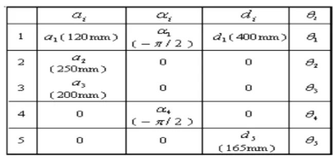
Since, the multi degree of freedom robotic control system has nonlinear and complicated dynamics behaviour, it is difficult to establish an appropriate dynamic model for the model based controller design, especially for the onboard microprocessor. Here the sliding mode concept [12-14] is combined with fuzzy control strategy to design a model-free fuzzy sliding mode controller (FSMC) for robotic motion control. In addition, the fuzzy variables gains scheduling strategy is integrated into the model-free fuzzy sliding mode control scheme for improving the transient response and steady state error performance. Theoretically, it will gradually approach the control objective, the origin of a phase plane. The fuzzy sliding control scheme with fuzzy variables gain scheduling control block diagram is shown in Fig. 2. It is an enhanced and extended development from the original FSMC approach proposed by Huang and Lin [9] to achieve excellent performance.
Here, a fuzzy logic control is employed to approximate the nonlinear function of equivalent control law, . The control voltage change for each sampling step is derived from fuzzy inference and defuzzification calculation instead of the equivalent control law derived from the nominal model at the sliding surface. It can eliminate the chattering phenomenon of a traditional sliding mode control. The controller design does not need a mathematical model and without constant gain limitation. The system control block diagram is shown in Fig.2.
The one dimensional fuzzy rules, Fig, 3(b), is designed based on the sliding surface reaching condition,
ueq
<0
⋅ s&
s . The
sliding surface variable, , is employed as the one dimensional fuzzy input variable.
s
A sliding surface on the phase plane is defined as Here, eleven fuzzy rules are employed in this control system to obtain appropriate dynamic response and control accuracy.
The input membership functions are scaled into the range of -1 and +1 with equal span. Hence a scaling factor is employed to map the sliding surface variable, , into this universe of discourse. A scaling factor is employed to adjust the value of control voltage. Membership functions of fuzzy input and output variables, and the fuzzy rules of the FSMC are shown in Fig. 3(a) and 3(b), respectively.
gs s gu
( ) ( )e1 e2 e1
dt
t d (5)
s = + λ = + λ
Where are defined as the state control errors. This sliding variable, , will be used as the input signal for establishing a fuzzy logic control system to approximate the specified perfect control law, . With this perfect control law, the closed loop control system has an asymptotical stability dynamic behavior [9].
i id
i x x
e = − s
ueq
The membership function used for the fuzzification is of a triangular type. The function can be expressed as
s&(t)+λs(t)=0 (6) Since λis a positive value, the sliding surface variable, , will gradually converge to zero. Based on the definition of sliding surface variable, , in eq. (5), the system output error will converge to zero, too. In this study, a fuzzy system is employed to approximate the mapping between the sliding variable, , and the control law, , instead of model-based calculation. This control law may have certain difference with the perfect control law , then the following equation can be derived.
s s
u
s u
eq
(x) 1 ( x a w)
μ = w − − + (9) where w is the distribution span of the membership function,
x is the fuzzy input variable and is the parameter corresponding to the value 1 of the membership function. The height method is employed to defuzzify the fuzzy output variable for obtaining the control voltage of each joint control motor. Which is a nonlinear function derived from the fuzzy inference decision and defuzzification operation.
a
∑ ∑
∑
∑
∑
≡⋅
=
⋅
= m m j j
l j m
l
j j
m
l j m
l
j j
C C
U u
1
φ μ
μ μ
μ (10)
s&(t) = −λs(t)+b(X,t)[ueq(t)−u(t)] (7) Generally, is a positive constant or a positive slow time-varying function for practical physical systems. By multiplying both sides of the above equation with gives
) ( X b
s where m is the rules number and is the consequent parameter. Here, eleven equal-span triangular membership
Cj
s(t)s&(t)=s(t){−λs(t)+b(X,t)[ueq(t)−u(t)]} (8)
3 Copyright © 2010 by ASME
functions are used for the fuzzy input variable, , and the fuzzy output variable, u.
s
The divisions of this membership functions can be expanded or shrunk by changing the scaling parameter of membership functions. The gain scheduling parameter is used to map the corresponding variables into this nominal range. In human beings’ intuition, when the joint angular error is large, the control voltage will be increased to provide more energy for driving the servo motor and reduce the angular error. On the other hand, when the error is approaching to the zero subset of membership functions, the controller should provide fine tuning to correct the little change of angular error and reduce the overshoot tendency. These two conditions can be traded off, by scaling the divided spans of membership functions with a parameter. These mapping parameters are specified as , and
for the sliding variable and control voltage, respectively, whose values are shown in Fig. 4 . The parameters values , , and for each joint are listed on Table 3. This approach is a novel gain scheduling 1D fuzzy sliding mode control structure. The values of these parameters are not critical for this gain scheduling fuzzy sliding mode controller. They can be roughly determined by simple experimental tests. Then the same values can be employed for different joint motion control with appropriate steady state accuracy. This control strategy can switch automatically between different scales and divisions of membership functions, by changing the gain scaling factor of membership function only.
gs gu
b
a
c d
5. EXPERIMENTAL RESULTS
In order to achieve desire motion specification and avoid the collision in the motion environment, the trajectory planning is required for the robotic motion control, and an appropriate controller is designed to monitor the end-effector motion trajectory. The multi axis manipulator is planned to execute point to point (PTP) motion or trajectory tracking control purpose in this study. The trapezoid speed curve motion trajectory is planned for PTP motion. Since the SOPC system is employed to implement this robotic servo control system, the control system cannot provide large computation ability for the model-based controller. Here, a model-free 1D fuzzy sliding mode controller is designed for each joint with gain scheduling scheme to control this Mitsubishi RV-M2 five DOF robotic system described in Section III. In order to evaluate the transient and steady sate control performances, the following experiments were performed. The sampling frequency in the experiments was 200 Hz. Since the sliding variable is divided into 11 fuzzy subsets from -1 to +1 with equal interval 0.2, a parameter is used to regulate the sliding variables into that range. A parameter was used to adjust the control input. The choice of these parameters is not sensitive to controller implementation. Their gain scheduling variation is designed as Fig. 4 and Table 3. If these parameters are varied within 50% and 200% of the original specified values, the
control system performance is not changed significantly. In order to display the outstanding performance of this intelligent novel controller, its dynamic responses are compared with that of a gain scheduling self-organizing fuzzy controller.
s gs
gu
Case (A): Each joint step response and working space PTP control
10o
In order to evaluate the transient and steady state responses of the proposed fuzzy intelligent controllers, each joint has
back and forth step motion is planned. The dynamic responses of each joint by using gain scheduling self- organizing fuzzy controller(SOFC) and fuzzy sliding mode controller (FSMC) are shown in Fig. 5(a) and 5(b), respectively for comparison. It can be observed that the dynamic response of FSMC has overshoot less than and steady state error less than . It is obviously less than the corresponding values, and of that of SOFC. In addition, the FSMC control strategy is employed to monitor the robot to move from a point to another point. The planning trajectory for the robotic end-effector is a trapezoid speed curve with a constant acceleration and deceleration for each joint, and it is moving from (0, 500, 200) mm to (400, 0, 300) mm in Cartesian space with 4 sec total motion time. The maximum angular acceleration of each joint is limited to . The motion trajectory in Cartesian space and the position error in each coordinate axis are shown in Fig. 6(a) and 6(b), respectively. The maximum angular tracking errors of each joint is less than . The overall position trajectory tracking error is less than 1.5 mm. The destination steady state position error is 0.03mm. Those data is obviously les than that of SOFC , 2.0mm and 0.1 mm. It is accurate enough for industrial applications.
10o
08o
. 0 01o
. 0 5o
.
25o
. 0
0 0.04o
15 . 0
sec2
/ 30o
o
Case (B) Trajectory tracking of end-effector moving in Cartesian space
In order to evaluate the trajectory tracking control accuracy by using this model-free FSMC intelligent controller, one straight line from (400, 0, 300)mm to (350, 100, 300) mm and one circle with radius 60mm and center (410, 0, 400)mm in X- Y plane of Cartesian space are planned for trajectory tracking experimental investigation. The position responses in Cartesian space and the position errors in X, Y and Z directions and contouring error of straight line trajectory are shown in Fig.
7(a) and (b), respectively. The position responses in Cartesian space and the position errors in X, Y and Z directions and contouring error of circular trajectory are shown in Fig. 8(a) and 8(b), respectively. The maximum angular tracking errors of each joint is less than . The contouring tracking error in Cartesian space is always less than 0.5 mm except the motion direction change position and the position tracking error in each coordinate is less than 0.5mm. These data are less than
, 1.5mm and 1 mm of that of using SOFC.
1o
. 0
2o
. 0
It can be concluded that the proposed novel intelligent FSMC controller has simple control structure and excellent
4 Copyright © 2010 by ASME
[8] Shiuh-Jer Huang and Ji-Shin Lee, “A Stable Self-organizing Fuzzy Controller for Robotic Motion Control,” IEEE Transaction on Industrial Electronics, Vol. 47, No. 2, pp.
421-428, 2000.
transient and steady state responses. It can be implemented on robotic system for industrial PTP and trajectory tracking control applications.
[9] Shiuh-Jer Huang and Wei-Cheng Lin, 2003, “Adaptive Fuzzy Controller with Sliding Surface for Vehicle Suspension Control,” IEEE Transactions on Fuzzy Systems, Vol. 11, No. 4, pp. 550-559.
6. CONCLUSION
A SOPC control structure is implemented on a retrofitted Mitsubishi 5 DOF robot for motion control. The model-free fuzzy sliding mode controller was developed for each joint and coded inside the FPGA chip for each joint motion control of this robot. This control strategy has model-free and gain scheduling advantages for achieving good transient and steady state responses. The controller is easy to design and implement.
It can reduce the computing time and data base for onboard system consideration. The experimental results show that this FSMC intelligent control system can effectively monitor the robotic end-effector to track various trajectories planned in Cartesian space with good control accuracy. This SOPC+FSMC control structure can be employed in pick-and- place, assembly and trajectory flowing operations.
[10] L.T. Wang and C.C. Chen, “A Combined optimization Method for Solving the Inverse Kinematics Problem of Mechanical Manipulator,” IEEE Trans. On Robotics and Automation Vol.7, N0.4, 1991.
[11] K. Kazerounian, “On the Numerical Inverse Kinematics of Robotic Manipulator,” AMSEJ of Mechanisms, Transmissions and Automation in Design, Vol.109, pp8- 13,March 1987.
[12] Utkin V. I., “Variable structure systems with sliding modes,” IEEE Trans. On Automatic Control, Vol. AC-22, no. 2, pp 212-222, 1977.
[13] Slotine J-J. E., Applied nonlinear control, Prentice Hall, 1991.
ACKNOWLEDGEMENTS
The authors would like to thank the financial support of Taiwan National Science Council under the contract NSC-98- 2221-E-011-079.
[14] Edwards Ch. And Spurgeon S. K., Sliding Mode Control – Theory and Applications, Taylor &Francis Ltd., London, Bristol, 1998.
[15] Hwang G. C. and Lin S. C., “A stability approach to fuzzy control design for nonlinear systems,” Fuzzy Sets Systems, Vel 48, pp.269-278,1992.
REFERENCES
[1] F. J. Lin, D. H. Wang and P. K. Huang, “FPGA- based Fuzzy Sliding-mode Control for a Linear Induction Motor Drive,” Proceedings of the IEEE Int. Conf. on Electrical Power Application, Vol. 152, No. 5, pp. 1137-11148, Sept.
2005.
Table 1 D-H parameters of Mitsumishi RVM2 robot
[2] Y. S. Kung and G. S. Shu, “Development of a FPGA-based Motion Control IC for Robot Arm,” Proceedings of the IEEE Int. Conf. on Industrial Technology, pp. 1397-1402, 2005.
[3] M. Okura and K. Murase, “Artificial Evolution of FPGA that Control a Miniature Mobile Robot Khepera,”
Proceedings of the Autonomous Minirobots for Research
and Edulainmente (AniiRE2003), pp. 103-111, 2003. Table 2 The parameters of MIMO trapezoid speed curve trajectory planning.
[4] Sprros Tzafestas and Leonidas Dristsas, ”Combined Computed Torque and Model Reference Adaptive Control of Robot System,” Journal of the Franklin Institute.Vol.327, No.2, pp. 273-294,1990.
[5] Ho-Hoon Lee and Fred E. Chlick, "Design of a Adaptive Control Law for Robotic Manipulator,”Journal of Robotic Systems, Vol.11, No.4, pp. 241-255,Jun.1994.
[6] Louis-A Dessaint; Marouf Sand; Bernard Hebert,"An Adaptive Controller for a Direct-drive SCARA Robot,”
IEEE Trans. On Industrial Electronics, Vol.39, No.2, pp.105-111, April.1995.
[7] Shiuh-Jer Huang and Ruey-Jing Lian, "A Hybrid Fuzzy Logic and Neural Network Algorithm for Robot Motion Control," IEEE Transaction on Industrial Electronics, Vol.
44, No. 3, pp. 408-417, 1997.
5 Copyright © 2010 by ASME
Table 3 The fuzzy gain scheduling control parameters.
Fig. 4 Gain scheduling parameters variation of FSMC controller.
(a)
Fig. 1 SOPC Robotic control system structure.
(b)
Fig. 2 Fuzzy sliding mode control block diagram.
(a)
(b)
Fig. 5 Joints step responses by using gain scheduling (a) SOFC control algorithm (b) FSMC control strategy.
Fig. 3 (a) Sliding variables fuzzy membership functions (b) joints fuzzy control parameters and fuzzy control rules.
6 Copyright © 2010 by ASME
(a) (a)
(b)
(b)
Fig. 6 (a) PTP motion response in Cartesian space and (b) Position tracking error in X, Y and Z directions and 3D contouring error.
(a)
Fig. 8 (a) A circular trajectory tracking in Cartesian space and (b) Position tracking error in X, Y and Z directions and 3D contouring error.
(b)
Fig. 7 (a) A straight line trajectory tracking in Cartesian space and (b) Position tracking error in X, Y and Z directions and 3D contouring error.
7 Copyright © 2010 by ASME