ᄲ̤ഛЭ⥆⻞મҚ₇⃥ʠ֯ᆹ̗ሺഛЭⲲ⯋
׆ࣔᔃ
তઝݾՕᖂሽᖲՠ࿓ߓ
ၪ ⣬
ء֮ಾኙᑇۯᐙቝಖᙕڜ٤ߓอհܛழۻࣚᐙቝಳ᠋༼נԫ១ڶயऱ
ֱऄΖᑇۯᐙቝಖᙕڜ٤ߓอ܌ࣚႚอᣊֺڜ٤ߓอհរΔؘႊࠠໂᐙቝ ೠྒྷΕڜ٤ᤞΕጻሁຏಛΕፖܛழۻࣚಳ᠋פ౨Ζء֮ଈ٣༼נאᔞᚨࢤ ᜯଖഗ៕ऱᐙቝೠྒྷֱऄ܌ࣚᛩቼॽ৫ऱ᧢֏ΔࠀᑑقᐙቝᢰΔא૯ זऄࠐ։ڍଡฝ೯ढ᧯Δ൷ထܓش։໊ፖᒵࢤฝ೯ऄאᆏપᓤᠧૠጩழ
ၴۖݙګܛழᐙቝಳ᠋פ౨Ζ່৵ء֮אԫڍଡฝ೯ढ᧯հᐙቝೠྒྷፖܛழۻ
ࣚಳ᠋ኔ᧭Δ᧭ᢞءߓอհᚌរፖڶயࢤΖ
〦⼫⥱Řᑇۯᐙቝಖᙕڜ٤ߓอΔܛழۻࣚಳ᠋ΔᐙቝೠྒྷΖ
REAL-TIME SERVO VISUAL TRACKING OF DIGITAL VIDEO RECORDER SECURITY SYSTEMS
Ming-Shyan Wang
Department of Electrical Engineering, Southern Taiwan University Tainan County, Taiwan 710, R.O.C.
Key Words: digital video recorder security system, object detecting, real-time servo tracking.
ABSTRACT
A simple but effective algorithm of real-time servo visual tracking for a digital video recorder security system (DVRSS) is proposed. The DVRSS, which overcomes the drawbacks of a traditional analog video-based security system, provides functions of object detecting, security alarming, network communication, and real-time servo tracking. An object detecting algorithm based on adaptive thresholding to surmount the effect of light level variation is presented. Additionally, an iterative method is introduced to distinguish multiple moving objects by marking the image with bounding-boxes. A motion tracking algorithm based on region division as well as linear translation is used to cope with the computation-intensive problem and complete real-time operation. Finally, an experiment involving detecting and real-time servo tracking of multiple moving objects is presented to illustrate the outstanding merits and effectiveness of the DVRSS.
I. INTRODUCTION
Traditional analog video-based security systems have many known shortcomings. For example, human labor involved in replacing tapes, distortion on recycled tapes, short recording time, images affected by the changing intensity of light, low efficiency in finding abnormal conditions due to sequentially searching through tapes, and the fact that vision functions cannot be merged into video recorders. Thus, these defects have motivated researchers to develop digital video recorder security systems (DVRSS’s) that at least provide functions of object detecting and real-time servo tracking [1], [2] to detect the intrusion of moving objects and enhance the monitoring of abnormal conditions [3]. Another function which should be considered is the transmission of an alarm message through network and telephone systems.
Object tracking (or visual tracking) has become an important topic in computer vision and robotics fields. Some basic functions such as real-time, automation, and robustness to non-ideal situations, are required for practical visual tracking systems [4,5]. The servo control structure in real- time visual tracking systems usually belongs to the category of “image-based” and “dynamic look and move” [4]. A hybrid approach of template matching and contour matching together with a visual probability data association (VPDA) filter in [5]
were employed to track an arbitrary-shaped object. A novel method of window-based tracking, replacing the original two-dimensional window with a pair of one-dimensional windows [6], was proposed for continuously tracking a target in the image plane to reduce the computation complexity. In [7], by using connected components to find the geometric center of the image plane, a window-based tracking technique was used for tracking symmetric targets after locating the target in binocular images. A multi-purpose real-time visual tracking system [8] adopted a region-based matching approach to estimate the motion of the moving target and activated its servo control unit so that the moving target’s image was kept in the center of the monitoring screen.
An object tracking and monitoring mechanism usually uses step motors to rotate and manipulate the PTZ (pan/tilt/zoom) camera, however, this system includes drawbacks of slow response and maximum value of about 120 rpm, small output torque, and imprecise positioning. On the contrary, a servomotor control system has advantages of high torque-to-inertia ratio and power density to overcome these deficiencies.
Image and video compression/decompression is one of main techniques for object detecting/tracking. This has led to the development of many algorithms for compression/
decompression and some international standards, which include motion-JPEG (Joint Photographic Experts Group), MPEG-4, and H.264. Strictly speaking, motion-JPEG is not properly standardized. Both MPEG-4 and H.264 are more mature and more concerned with compression of image data than motion-JPEG. Additionally, MPEG-4 emphasizes flexibility whilst H.264 concentrates on efficiency and reliability. The licensing situation for MPEG-4 is clear but remains to be agreed for H.264 [9]. Motion-JPEG has the disadvantages of the lowest compression rate and the largest disk space for storage because it compresses each image in the sequence according to the same rules. However, it needs less specialized hardware, and there exists no correlation between successive images, such that an error in one image will not corrupt the following images. Furthermore, it has no need for licensing [10]. These merits are very useful for DVRSS’s users.
In the paper, a specially designed, rotary video camera with a PMSM is introduced to aim at intrusive moving objects.
Besides simple algorithms used for object detecting and tracking in the DVRSS, the modified motion-JPEG approach with JPEG baseline standards is used to compress the recorded data for sequential image processing and data management.
The paper is organized as follows. The DVRSS, divided into DVR module, servo control module, and alarm and network module, is described in Section II. Servo tracking is introduced in Section III. Experimental results are presented in Section IV. The conclusions are given in Section V.
II. DVRSS DESCRIPTION
The proposed DVRSS includes three major modules: the DVR module, the servo control module, and the alarm and network module [11].
A digital video recorder (DVR) may be realized through one of three different integrated systems, PC plus Windows OS, PC plus Linux OS, and the embedded RISC 32-bit system.
Since PC plus Windows OS is the most popular system, the designed DVR module consists of a PC, an image capture card with rate of 30 frames per second, and a 6 mm video camera. Captured video with size of 320×240pixels is sent to the PC and checked for whether there is any moving object.
There exist some advantages of using motion detection before
PC
Microcontroller 8051 Input
channels
Servo motor drive Stepper
driver stepper
Relay
Output channels
PMSM RS232
Table 1 Parameters of PMSM
Output power
PR 300W Back EMF constant
KE 54.9V/Krpm
Torque TR 0.95NΗm Inertia JM 0.224KgΗcm2
Rated current
IR 2.0A Stator resistance
Ra 2.79Ω
Rated velocity
NR 3000RPM Stator inductance
La 5.80mH
Torque constant
KT 0.524Nm/A
tracking a moving object. For example, it provides important clues to a tracking system and determines a smaller search range to reduce computation time [5].
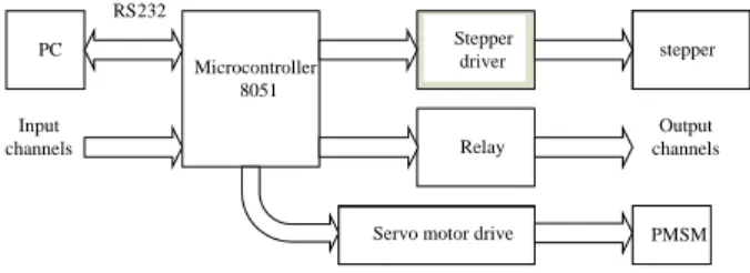
The servo control module shown in Figure 1 contains a permanent-magnet synchronous motor (PMSM) 7CB30 and its drive, a step motor, and a control board that includes a microcontroller 8051 and the step motor drive. The PMSM 7CB30 with parameters revealed in Table 1 is employed to horizontally activate the camera to track the target. The step motor 4T8618M0401 has the specifications of step angle of1.8o, rated voltage of 7.4 V, and rated current of 1.0 A, and controls the camera in up-down motion, as the up-down directional frequency is very slow. Based on the data collected from the moving object, the PC judges the direction and speed of the moving object to generate the instruction codes for the control board. Finally, the speed/position commands are executed by the servomotor and step motor to orient the camera to the correct position for real-time tracking.
The alarm and network module is comprised of the PC with network hardware, alarm devices, and communication equipment that provides remote monitoring functions, camera controlling, and image recording. The modified motion-JPEG approach with JPEG baseline standard programmed in Visual C++ language is applied to compress and decompress recorded images, which includes color conversion, data sampling, image segmentation, discrete cosine transform (DCT) and inverse DCT (IDCT), image quantization and dequantization, Huffman coding and decoding [3,12]. As soon as any intrusion happens, the PC begins to record the images.
Operations of DCT, image compression, and data storage onto the hard disk would then be executed. In addition, an event-based (and/or time-based) searching approach is used to speed up searching for intruding objects in the PC. This searching approach provides much more efficiency than sequentially searching in an analog system.
Due to the prevalence of networks and communication systems, the intra-network is designed in the security system
Fig. 1 The servo control module
such that it can supply the function of remote control by using a data transfer technique, such as Java, web server, active server pages, or active data object. Moreover, the network-based DVRSS, without installing any specific software packages, provides users with a remote monitoring and alarm generation if one of several preset abnormal conditions is met. The alarm signal may be transmitted by e-mail, telephone, mobile phone, BB call, and/or FAX.
III. SERVO TRACKING
The algorithm of motion detection is based on frame difference technique, whereby an image with a difference of
) , (x y
d is considered for substantial difference pixel by pixel in gray-levels between consecutive images, f1andf2,
| ) , ( ) , (
| ) ,
(x y f1 x y f2 x y
d = − (1)
where x and y stand for width and height, respectively.
Before detection, low-pass filtering is first performed to minimize the effect of noise; down-sampling is then operated to reduce overall pixel dimensions of the image, which also reduces computation time. The equation for down-sampling is
1 1
0 0
ˆ ˆ 1 ˆ ˆ ˆ ˆ
( , ) (2 ,2 ), / 2, /2
d 4
j i
g x y d x i y j x x y y
= =
=
∑ ∑
+ + = = , (2)wheregd(xˆ,yˆ) is the transformed image. To segment the moving object and background of an image, gray-level thresholding is adopted because it is a simple segmentation method which allows image processing at low computation cost [3]. Thresholding is the transformation of an input image f to its output binary image gt defined as follows:
<
= ≥
, ) , ( 0
, ) , ( ) 1
,
( for f i j Th
Th j i f j for
i
gt (3)
where Th is the global-threshold value dependent on ambient
maximum gray level
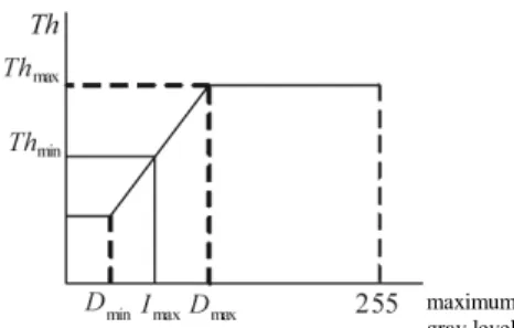
Fig. 2 Relation between critical gray level and threshold
Fig. 3 Spatial filtering for slightly camera shaking
illumination, and gt(i,j)=1 stands for image elements of background.
Two problem conditions are general in object detection, one is lightness variation and other is camera shaking. For the first condition, an adaptive thresholding algorithm is considered to overcome the effect of light level variation.
Based on experimental results, Figure 2 discloses the relationship between the maximum gray-value of current image,Imax, and its corresponding threshold [3]. If Imax is greater thanDmax, the environment is regarded as a normal light level, then Thmaxis used as a threshold; if Imax is less than Dmax and greater than Dmin , the environment is considered to be dark, and then the relationship between threshold Th and gray level D is a linear mapping. However, if
Imaxis less thanDmin, then Thminis chosen.
In the second condition, the camera shaking may generate a false alarm of motion detection even if there is no intrusion of any moving object. This is because the noisy result from camera shaking will affect the determination of detecting moving objects. A spatial filter is utilized to remove the camera shaking, described in Figure. 3, where P is the central pixel. After thresholding on each frame, if P is non-zero, eight neighboring pixels of P, i.e., from P1 to P8, are summed up. If the summation of P1 to P8 is smaller than 2, P is set to zero.
For multiple moving objects, an iterative method is used to distinguish objects by first creating binary images of the moving objects then marking them with bounding-boxes according to different sizes of objects [13]. The bounding-box containing the largest area of video is selected as the major
(a)Original projection; (b)First column projection;
(c) First row projection; (d) Second projection;
(e) Result
Fig. 4 Iterative processes for multiple moving objects
candidate for motion tracking. For example, the binary image in Figure 4(a) is scanned from left column to right column, and the vertical lines that have non-zero values in each column are recorded, disclosed in Figure 4(b). The same operation is executed for rows, shown in Figure 4(c). The iterative process goes on, shown in Figure 4(d), until all rectangular bounding-boxes are located, presented in Figure 4(e).
A simple but effective algorithm based on region division as well as linear translation for motion tracking is used to cope with computation-intensive problems. An image frame is divided into many active areas and one tolerance area [2] as shown in Figure 5, in which W and H denote the width and height of the frame, respectively. The tolerance area is about 1/16 of a frame and the remaining area is divided into three types of rectangles, A, B, and C. Each rectangle represents the discrete position of the servomotor being moved. If the center of the moving object falls within the tolerance area, the servomotor remains still. If the center of coordinates of the moving object falls in the active areas, the servomotor will be activated to move the corresponding rectangle into position.
P1 P2 P3 P4 P P5 P6 P7 P8
(a) (b)
(c) (d)
(a) (b)
(c) (d) W
A B
C H
D
1/4W
1/4H Tolerance
area
Fig. 5 Frame dividing
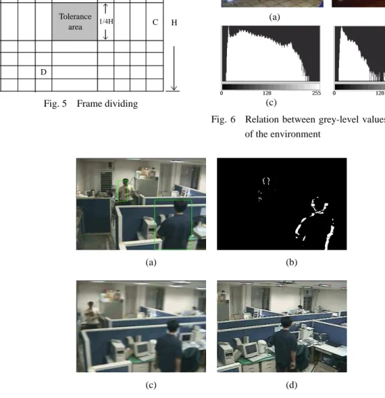
Fig. 7 Moving detection and single tracking of multiple moving objects
(a) Two moving objects in the image. (b) The frame difference between two consecutive images.
(c) Camera moves towards larger moving object. (d) Camera stops tracking when the object is standing still.
Apparently, the moving path needs much less computation than the optical-flow and motion-estimation based approaches. Although such a translation-based path calculation may generate a rough trajectory, this is allowable as the purpose of a DVRSS is to monitor moving objects, not to find precise motion trajectories.
IV. EXPERIMENTAL RESULTS
In a normal environment, the image presented in Figure
6(a) has higher averaged grey-level values as shown in Figure 6 (c). On the contrary, the image shot in a dark environment and presented in Figure 6(b) has lower averaged grey-level values as shown in Figure 6 (d). Thus, a higher threshold is adopted in the former and a lower one in the latter to obtain better results. After trials, the DVRSS with the parameters of
max max
min 5,Th 20,D
Th = = =128, and Dmin=20 will exhibit excellent results [11]. Figure 7 exhibits motion detection and single tracking of multiple moving objects. There are two moving objects of different sizes in Figure 7(a). Figure 7(b) depicts the frame difference between two consecutive images.
Fig. 6 Relation between grey-level values and light level of the environment
By using the iterative method, the bounding-boxes of different sizes are determined, shown in Figure 7(a). Figure 7(c) shows that the PMSM activates the camera to track the larger moving object. Figure 7(d) shows that the camera stops tracking when the object is standing still.
V. CONCLUSIONS
A DVRSS has utilized the merits of servo drives to speed up the response of object tracking. In addition, while executing object detecting, it uses an adaptive thresholding algorithm to overcome the effect of light level variation. The iterative process that goes on marking binary images of moving objects with bounding-boxes until all rectangular bounding-boxes located, has also been proposed to select one candidate among multiple moving objects for tracking. A region-based as well as a translation-based algorithm for motion tracking is used to cope with the computation- intensive problem. The presented experimental results have shown the effectiveness of the proposed algorithms.
ACKNOWLEDGMENTS
The author would like to express his appreciation to Prof.
Tsai, Mi-Ching, Prof. Chen, Thou-Ho, Prof. Chen, Fu-Kun, Gao, Cheng-Liang, and Wu, Chiang-Chuan for their assistance.
REFERENCES
1. Cretual, A., and Chaumette, F., “Application of Motion-based Visual Servoing to Target Tracking,”
International Journal of Robotics Research, Vol. 20, No.11, pp. 878-890 (2001).
2. Linda, G. S., and Stockman, G. C., Computer Vision, New Jersey: Prentice Hall, USA (2001).
3. Rafael, C. G., and Woods, R. E., Digital Image Processing, Second Edition, NJ, USA (2002).
4. Hutchinson, S., Hager, G. D., and Corke, P. I., “A Tutorial on Visual Servo Control,” IEEE Transactions on Robotics and Automation, Vol. 12, No.5, pp. 651-670 (1996).
5. Chen, P.-B., Huang, C.-M., and Fu, L.-C., “A Robust Visual Servo System for Tracking an Arbitrary-shaped Object by a New Active Contour Method,” Proceedings of the 2004 American Control Conference, Vol. 2, pp.
1516-1521 (2004).
6. Song, K. T., and Wu, T. Z., “Visual Servo Control of a Mobile Manipulator Using One-dimensional Windows,”
Proceedings of IEEE IECON'99, Vol. 2, pp. 686-691 (1999).
7. Chang, W.-C., and Lee, S.-A., “Autonomous Visual Servoing with Tele-supervision,” Proceedings of the 2004 IEEE International Conference on Networking, Sensing and Control, Vol. 2, pp. 82-87 (2004).
8. Wang, C.-K., Cheng, M.-Y., Liao, C.-H., Li, C.-C., Sun, C.-Y., and Tsai, M.-C., “Design and Implementation of a Multi-purpose Real-time Pan-tilt Visual Tracking System,” Proceedings of the 2004 IEEE International Conference on Control Applications, Vol. 2, pp. 1079-1084 (2004).
9. Richardson, I. E. G., H.264 and MPEG-4 Video Compression—Video Coding for Next-generation Multimedia, London: John Wiley and Sons Ltd, England (2003).
10. Symes, P., Video Compression Demystified, NY, USA (2001).
11. Wang, M.-S., Gao, C.-L., Chen, C.-H., and Wu, C.-C., “A Network-based Digital Video Recorder Security System with Real-time Servo Image Tracking,” IEEE/ASME International Conference on Advanced Manufacturing Technologies and Education, Chia-Yi, Taiwan, Aug.
11-14, paper no. B139 (2002).
12. Umbaugh, S. E., Computer Vision and Image Processing:
A Practical Approach Using CVIPtools, NJ, USA (1998).
13. Capellini, V., Mattii, L., and Mecocci, A., “An Intelligent System for Automatic Fire Detection in Forests,” IEEE Third International Conference on Image Processing and its Applications, pp. 563-570 (1989).
2007ڣ 06 ִ 29 ֲ گᒚ 2007ڣ 08 ִ 01 ֲ ॣᐉ 2008ڣ 04 ִ 28 ֲ ᓤᐉ 2008ڣ 05 ִ 15 ֲ ൷࠹