國立臺灣大學工學院機械工程學研究所 博士論文
Department of Mechanical Engineering College of Engineering
National Taiwan University Doctoral Dissertation
創新式薄膜及腔體設計於 可分離式壓電薄膜微型泵之研究
Study of Innovative Diaphragm and Pump Chamber Design in Separable Piezoelectric Micropumps
羅文甫 Wen-Fu Luo
指導教授:馬小康 博士 Advisor: Hsiao-Kang Ma, Ph.D.
中華民國 108 年 7 月
致謝
我的博士生涯是一條曲折的路,一路上有好多要感謝的人。
感謝馬小康老師讓我暫停學業專心創業,然後在公司穩定之後又再回到學 校來準備口試,我在出去外面闖盪之後才發現您的訓練是我創業最大的後 盾。感謝您與孫維仁老師鼓勵及要求我們參與課外活動,並與不同領域的 人合作,甚至透過競賽培養技術商業化的能力及說服他人的技巧。從洗滌 出有價值的 business model 到申請計畫的計畫書撰寫,我發現我創業中 的每一步均是受到恩師小康的訓練而完善,我真心的感謝您,您對邏輯思 考的訓練使我發掘了創業的機會。
我的伴侶亦是在這段期間出現,小阿是我生命中的天使,你教了我紀律、
不服輸還有對事物保持懷疑仔細分析的態度,你不但是我創業上最重要的 夥伴,更是我論文得以完成的關鍵。你是一位嚴格又溫柔的伴侶,在我遇 到挫折時安慰我、在我鬆懈時砥礪我、更在我一度想要放棄回學校時鞭策 我扛起更大的責任,使我得以空出時間完成論文,你是我的伴侶、摯友兼 良師,沒有你我不可能完成這本論文。
最後要感謝讓我沒有後顧之憂的家庭,以及我親愛的實驗室夥伴小芮、于 萱、元朧、科科、季昕、聖惟、榮暉、寧祥,我很高興我們能組成一個完 美的 team,並且在所有人都開始工作後仍能保持聯繫,你們的支持是這本 論文得以完成的另一關鍵。
最後謝謝機械工程研究所,我愛機械所,並以成為其中的一份子為榮。
Abstract
Two series of innovative separable piezoelectric micropump has been developed to provide low-cost liquid delivery for medical applications. The actuator of the proposed micropump can be used repeatedly to reduce costs, and the pump chamber is disposable to prevent contamination as well as infection. The micropump was actuated by a piezoelectric plate measuring 22×40×0.7 mm and the operating voltage was AC 50 to 80 V.
In the series-1 pumps, a unique bossed diaphragm, with a cylindrical protrusion at its center, was designed to not only facilitate contact between the diaphragm and piezoelectric actuator but also to overcome the adhesive force, which is a major challenge facing separable micropumps. According to the results of experiments, the adhesive force caused by residual liquid in the pump chamber may adversely affect the resilience of the diaphragm, leading to an insufficient liquid supply. The results show that the thickness and bossed ratio of the diaphragm have a major effect on the flow profiles. The flow rate of the proposed optimal series-1 micropump, with a 0.3-mm bossed diaphragm and 1-mm-depth pump chamber, can be modulated from 1.58 to 6.21 ml/min at frequencies of less than 20 Hz, and the pump head can reach a maximum of 200 mm-H2O.
The series-2 separable pump has been developed continuously to achieve a robust flow
rate when the pump head is not constant. A diaphragm, comprised by a silicone rubber membrane and a PET base is used to achieve the easy modulation of diaphragm stiffness. The diaphragm stiffness is mostly determined by the PET base, which can be manufactured by precision CNC machine. Moreover, a novel pump chamber with a center column is designed and manufactured. The center column can be seen as a diaphragm deformation boundary that will restrict the diaphragm displacement to a specific value. The results show that the designed pump can provide a constant flow rate within a specific range of pump head. The flow rates of pump AX, chamber with a 1mm height center column and 1.5 mm depth, are 1.78 ml/min until the pump head is higher than 20 cm-H2O at 1 Hz. Another design, pump AY, with a same diaphragm and a higher center column of pump chamber, can provide a constant flow rate until the pump head is higher than 25 cm-H2O at 1 Hz.
Keywords
Piezoelectric; Separable micropump; Bossed diaphragm; Adhesive force; Pump chamber; Robust flow
中文摘要
本研究發展了兩類型的分離式壓電幫浦以滿足低成本的醫用輸液需求,此類型的 幫浦其驅動元件可重複使用降低成本,而幫浦腔體及流道部分則可單獨拋棄來避 免感染。前述的驅動元件為一個 22X40X0.7mm 的長方形壓電片,並可以 50-80V 之交流電驅動。
在 Series-1 幫浦中,我們採用了一個獨特的中央凸起型薄膜,此設計不但可充 當驅動元件與薄膜之間的接觸點,同時亦可用來克服分離式幫浦主要挑戰之一的 吸附力問題。無論透過理論分析或實驗均可得知在排出週期中殘留於幫浦底部的 液體將會對薄膜產生吸附力,此吸附力可嚴重影響薄膜回彈,造成幫浦得失效。
實驗結果顯示改變中央凸起之大小及薄膜厚度可有效改變幫浦特性,最佳化設計 的 Series-1 幫浦(0.3mm 薄膜/Br=0.75 搭配 0.1mm 薄膜)在頻率不超過 20Hz 的
前提下可提供 1.58-6.21 ml/min 的流量,並能產生最高 200 mm-H2O 的揚程。
為了達成流量在不同背壓下的一致性,我們進一步發展了 Series-2 分離式幫浦 系列,本系列幫浦採用了複合式薄膜設計,藉由矽膠薄膜與相對剛性較強的 PET 骨架結合,由於整體剛性由 PET 骨架所控制,因此只要 CNC 製作的 PET 骨架形 狀,就可以輕鬆改變整體等效剛性。此外,本研究亦提出一個創新的具有中央柱 之幫浦腔體設計,此中央柱在薄膜被驅動元件下壓時可充當薄膜下壓深度之限制 邊界,也就是無論操作條件為何,薄膜之下壓幅度以及每次之體積變化量均相等,
進而產生穩定之幫浦流量。結果顯示此設計可在一定背壓範圍內產生相同之流量,
當背壓不高於 20 cm-H2O 時,幫浦 AX(腔體深 1.5mm/中心柱高 1mm)在 1Hz 下之流 量不隨背壓變化均為 1.78 ml/min,而另一個幫浦 AY,因為其具有更高之中心柱
(更嚴格之幫浦下壓限制),因此流量可以在更大的範圍內(0-25 cm-H2O)均保持
恆定。以上之容忍背壓範圍均符合臨床靜脈輸液需求,具有進一步應用之潛力。
關鍵字
壓電元件; 分離式幫浦; 中央凸起式薄膜; 幫浦腔體; 流量穩定性
Table of contents
1 Introduction 1
1.1 Background 1
1.2 Types of micropump 2
1.3 Applications of medical pumps 4
1.4 Challenges on clinical use of piezoelectric micropumps
4
1.5 Current development of separable micropumps 6
1.6 Goal of this study 9
2 Development of our first separable piezoelectric micropump
11
2.1 Challenges presented by separable piezoelectric micropump design
11
2.2 Design of the separable piezoelectric micropump (Series-1 pumps)
13
2.2.1 Bossed diaphragm 14
2.2.2 Actuator 17
2.2.3 Pump chamber and valve 18
2.2.4 Fabrication 19
2.3 Theoretical analysis 22
2.3.1 Elastic force of diaphragm 23
2.3.2 Adhesive force acting on diaphragm 25
2.3.3 The piezo electric theorem 28
2.4 Experiments- material & methods 34 2.4.1 Set-up of the performance test 34 2.4.2 Instruments used in the experiments 36 2.5 Results and discussion of the experiments 41 2.5.1 Effect of pump chamber depth on flow rates 41 2.5.2 Effect of diaphragm thickness and bossed ratio 44
2.5.2.1 Diaphragm thickness, d 44
2.5.2.2 Bossed ratio, B
r45
2.5.3 Pump performance under certain pressure heads 48 2.6 Summary of the series-1 separable pump 51
3 Development of the separable micropump with robust flow rates (Series-2 pumps)
52
3.1 The robustness of the flow rates 52
3.2 Development of piezoelectric micropump with robust flow rate
53
3.2.1 Design of pump chamber with a center column 54 3.2.2 Design of diaphragm with a PET base 57 3.2.3 Design of the actuator and valves 60
3.3 Theoretical analysis 61
3.3.1 Equivalent stiffness of PET base 61 3.3.2 Equivalent stiffness of diaphragm 63
3.4 Experiments on pump performance 65
3.4.1 Fabrication of the tested pumps 65
3.4.2 Experimental set-up 68
3.4.3 Instruments used in the experiments 70
3.5 Results and discussion 71 3.5.1 Effects of base design on diaphragm stiffness 71 3.5.2 Effects of base design on pump performance 73 3.5.3 Effects of chamber center column on pump
performance
75
3.5.4 Effects of back pressure on pump performance 78 3.6 Summary of the series-1 separable pump 80
4 Conclusions and future works 82
4.1 Conclusions 82
4.2 Future works 83
Reference 85
List of Figures
1-1 Separable valveless pump proposed by Kim 6 1-2 Separable pump with micro fan and motor 7 1-3 The separable thermo-pneumatic micropump 8 1-4 The separable drug delivery system 8 1-5 The electromagnetic separable micropump 9 2-1 Comparison of operation cycle of a (a) conventional
and (b) separable micropump
12
2-2 Schematic view of the proposed Series-1 separable pump with single-use and reusable part
13
2-3 Bossed diaphragm with integrated cylindrical transfer column
14
2-4 QC601A thermal-press-forming machine 17 2-5 The rectangular piezo actuator and the clamp layer 17
2-6 Passive bridge-type PDMS valve 19
2-7 Photograph of the fabricated separable pump, Series-1, and close-up of the actuator and diaphragm assembly
21
2-8 CNC machine for PMMA layers 22
2-9 Force diagram for a separable piezoelectric micropump during suction stage
23
2-10 C
adwith different bossed ratios and displacement of the center of diaphragm, y
c.
28
2-11 The deformation of the lattice and the displacement of the dipoles
29
2-12 piezoelectric and converse piezoelectric effects 30
2-13 The major operation types of piezoelectric actuators 33
2-14 Bimorph vibrating piezoelectric actuator 33 2-15 Experimental set-up for Series-1 separable pumps 35 2-16 Experiment set-up of the backpressure versus flow
rate tests
35
2-17 Low frequency function generator 36
2-18 Power amplifier 37
2-19 Tohnichi 15DB4 torque wrench 38
2-20 Large scale lifting platform 38
2-21 Precision lifting platform 39
2-22 High speed camera 40
2-23 Measured flow rate with different chamber depths at different frequencies
43
2-24 Measured flow rate with different diaphragm thicknesses at different frequencies
45
2-25 Measured flow rate with different bossed ratios and different voltages (Pump E at 5 Hz, d
ac= 0.3)
47
2-26 Measured flow rate with different bossed ratios and different voltages (Pump E at 10 Hz, d
ac= 0.3)
48
2-27 Measured flow rate of optimized pump (Pump E, Br = 0.75)
49
2-28 H–Q chart of optimized Series-1 pump, measured flow rate u different pump heads (Pump E, B
r=0.75)
50
3-1 Schematic view of pump chamber with the center column
57
3-2 The diaphragm with a silicone rubber membrane and PET base
59
3-3 The schematic view of rectangular piezo actuator with a blade
60
3-4 Passive bridge-type PDMS valve 61 3-5 The force diagram of the cantilever system 63 3-6 Schematic view of the designed micropump 66 3-7 Photo of the manufactured micropump 68 3-8 Diagram of the experimental set-up 69 3-9 Bose ElectroForce 3510 force-displacement testing
instrument
70
3-10 Theoretical and measured force-displacement relationship data
72
3-11 Flow rate of pumps without center column 74 3-12 Displacement of the force transmission column with
pump containing no center column
74
3-13 Photo captured by XS-4 high speed camera to measure the displacement of the force transmission column.
75
3-14 Flow rates under different frequency of each pump assembly
76
3-15 Displacement of the force transmission column with pump containing a center column
77
3-16 Flow rates when a backpressure is applied to the pump outlet
79
List of Tables
2-1 Parameters of the Series-1 separable piezoelectric pump
41
2-2 The calculated values of F
eand F
adwith different designs
42
3-1 Parameters of the pump chambers 57
3-2 Parameters of the diaphragm 59
3-3 The k
effof each component 64
Nomenclature
Br Bossed ratio
Cad Adhesive force coefficient dd Diameter of the diaphragm dp Diameter of the pump chamber t Thickness of the valve
D Flexural rigidity of circular plates E Young’s modulus of the diaphragm f Frequency of an input AC
Fad Adhesive force act on the diaphragm by the fluid Fe Elastic force induced by the deflection of diaphragm Fv Force required to open the valve
hc Height of the residual liquid under the central area of a bossed diaphragm hd Height of the center column of the pump chamber
hp Depth of a pump chamber H Pump head of the micropump Keff Equivalent stiffness coefficient ra Radius of the pump chamber rb Radius of the bossed area Q Flow rates of the micropump
tb Thickness of the base of the diaphragm wb Width of the base rib of diaphragm
yc Displacement of the center of a bossed diaphragm
1. Introduction 1.1 Background
The development of precision pumps has been the subject of considerable attention over the last decade. The commercialization of precision pumps has allowed the creation of highly accurate fluid delivery systems, which have been widely employed in the fields of chemical engineering and medicine. In medical applications, advancements have gradually shifted toward the development of precision pumps with ultra-low flow rates.
To achieve precise but controllable liquid delivery, conventional infusion pumps use servomotors as their actuators. Although servomotors are capable of extremely high levels of precision, their complex mechanical components and costly control circuitry render these systems uneconomical. More, applications are limited by its heavy weight and large size. Numerous new applications, however, such as homecare, patient controlled system and emergency rapid-transfusion heating systems, do not require the high accuracy of servomotor pumps; rather, the weight and cost of the servomotor pumps limits the scope of their application.
Compared to traditional servomotors, micropumps have the advantages of small size and lower cost. However, the micropump family includes huge types of pumps that working with different principles and actuators. Because the real clinical scenario, compared to the well-controlled laboratory environment, has a great variety and uncertainty. It is very
hard to verify and examine the interaction and mechanism between the human tissue, drugs and the pump. Thus, the safeties way in medical field is to use the “idle” pump that will only transfer minimal heat or other types of energy to the working fluid and have no potential of changing the physical or chemical characteristics of the fluids. Unfortunately, many types of micropumps cannot meet to the requirements and are not suitable to medical applications.
1.2 Types of Micropump
It is required to define the scope of micropump before the classification. In fact, compared to the size of common microelectromechanical systems, MEMS, most of the current commercialized types of micropumps have much larger structures which are far from the
“micro-scale”. However, to simplify the discussion, those commercialized types, including the piezoelectric pump developed in this study, are also generally called as micropumps because, indeed, they have much smaller structures compared to mainstream pumps for medical infusion.
Overall, micropumps can be divided into two categories: dynamic pumps and displacement pumps. Common dynamic pumps include electro-hydrodynamic [1] and magneto-hydrodynamic [2-3] pumps, in which a continuous driving force generated from the interaction between the electric/magnetic field and the working fluid is utilized to
pump the fluid. The valve is often not required in such micropump system due to the directly control of flow direction. Moreover, bi-directional micropumps can be achieved by controlling the electric/magnetic field. The big issue of such kind of pumps is the interaction on fluids. The clinical use is highly restricted before the influences on different kinds of tissues and drugs are fully analyzed.
In contrast to dynamic pumps, displacement micropumps generate flow rates when the driving element of the pump varies the pump chamber volume without influencing the working fluid. Without largely interacting with working fluids, displacement pumps are widely used in commercial applications. Based on different driving elements, they can be classified as piezoelectric [4-6], electrostatic [7], thermos-pneumatic [8], electromagnetic [9-10], shape memory alloy (SMA) [11], and ultrasonic [12]. Micropumps of shape memory alloy or thermos-pneumatic design may heat and influence the delivered liquids because heating is required to induce a volume change of pump chamber. The influence also raises some issues on clinical use, especially when protein based drugs are used because of their heat sensitive behavior [13]. Among these, the piezoelectric driving elements are extensively employed in the micropump design because of their high driving force, rapid response with short driving time, simple configuration, and reliable control method as compared with other micro-driving elements.
1.3 Applications of Medical Pumps
Common applications of medical pumps include drug infusion through veins or other channels (e.g., epidural space) and rapid blood transfusion. Drug infusion can be further categorized into micro flow rate infusion and high flow rate infusion. Micro flow rate infusion is often used in cancer chemotherapy or anesthetic drugs, in which the target infusion dose is small, requiring a considerably low flow speed and substantially high precision. So far, most pump products in the market can achieve precise infusion at a flow rate of 0.1–99 ml/h with a flow rate adjustment increment smaller than 0.1 ml/h [14-15].
It would be very difficult to replace the existing servo motor based infusion systems with piezoelectric pumps in micro flow rate infusion. Because the working fluid of fast transfusion is blood, which is highly viscous, and the required flow rate is usually higher than 70 ml/min, the piezoelectric element would not be suitable for this application.
Differing from the aforementioned applications, vein drug application has a normal flow rate in the range of 50–250 ml/h, which matches the flow rate range of micro piezoelectric pumps, making it a suitable application of piezoelectric pumps.
1.4 Challenges on Clinical Use of Piezoelectric Micropumps
Naturally, there are other challenges that are yet to be addressed before the micro piezoelectric pumps can be extensively used in medical devices. First, regardless of the
type of micropump, the problems of flow channel contamination and infection need to be overcome. Specifically, commercial products feature disposable flow channels to prevent infection and contamination. In addition, the actuators and other parts of pumps are easily separable, enabling the rapid replacement of used or damaged flow channels. However, most piezoelectric micropump designs feature an actuator integrated with the pump chamber, where the base of the piezoelectric component is bonded directly to the top of the diaphragm on pump chamber. Consequently, instead of simply discarding the chamber and retaining the more costly piezoelectric actuator, the entire pump must be discarded once it has been used. Therefore, developing a piezoelectric actuator in which the actuator can be separated from the pump chamber is necessary to reduce costs and avoid wastage.
For this type of pump, the potentially contaminated flow channel and pump chamber can be disposed separately after use while the expensive driving element can be reused.
Another challenge pertains to the robustness of the micropump. When used in clinical applications, the medical pumps infuse the fluid into the human body, and the infusion resistance or back pressure caused by the blood pressure has to be overcome. Because human blood pressure is not constant, the medical pumps must overcome the vein pressure ranging between 0 cm-H2O and 14 cm-H2O for vein infusion [16]. The driving force generated by the driving element of a micropump is smaller than that of a servo motor, and the flow rate varies with the change in the back pressure. Therefore, the
clinical applicability of the micro piezoelectric pumps depends on their ability to maintain a constant flow rate within a reasonable range.
1.5 Current Development of Separable Micropumps
A separable valveless pump fabricated by PDMS has been proposed in 2004 [17]. The diameter of the pump chamber is 3.5mm and the thickness is 80 μm. The flow controlling
component is a nozzle/diffuser combination, as shown in Fig. 1-1. The actuator, a circular piezoelectric element, was glued on a glass base and the actuator assembly then attached to the PDMS chamber. The PDMS chamber part can be removed after used and the
actuator can be repeatedly used to reduce the cost. The maximum flow rate can reach 32.9 μm/min while the maximum pump head can be 173 Pa. The study described the concept
of separable pump, however, the remove of the used chamber as well as the re-attached of the actuator is not easy for daily use in the hospital.
Fig. 1-1 Separable valveless pump proposed by Kim [17]. (a) The PDMS pump chamber (b) The assembly of piezoelectric disc and PDMS chamber
In 2006, R. Irawan [18] proposed a separable micropump manufactured by CO2 laser beam cutting machine. The pump chamber was made of PVC and PMMA, as shown in Fig. 1-2. Thus, the manufacture process is simple and the cost of material is low. The actuator of the micropump is a micro motor. A micro fan was mounted inside the chamber and the rotary shaft can be combined with the motor to generate fluid flow. The pump chamber can be disposed separately. The maximum flow rate is 15 ml/min.
Fig. 1-2 Separable pump with micro fan and motor [18]
Ha [19] developed a separable thermo-pneumatic micropump in which the actuator, a glass-based heating chip, can be used repeatedly, and the PDMS chip is disposable. (Fig.
1-3) The heating chip can heat the air inside the chamber to increase the volume. Liquids in the pump chamber can be pumped out when the volume of the air chamber is increased.
The maximum flow rate is about 60 μl/min and the power consumption is about 5 Watts.
Fig. 1-3 The separable thermo-pneumatic micropump [19]
A peristaltic pump actuated by four piezoelectric actuators has been developed by Liu [20], as shown in Fig. 1-4. However, different from other designs, the pump chamber cannot be separated from the actuator and the combination have to be disposed after use.
The only reusable part of whole design is the pre-filled drug chamber. The volume of the drug chamber, which is also the drug reservoir, is 3.2 ml and the minimum volume of single dose was about 0.06 μl.
Fig. 1-4 The separable drug delivery system [20]
In addition, a separable piezoelectric with a bi-chamber and magnetic membrane design was proposed [21]. (Fig. 1-5) A magnet was combined with the membrane and the actuated part, the electromagnet and its circuit, was separable and reusable. The pump has a high flow design. The maximum flow rate of this pump can reach 170 ml/min.
Fig. 1-5 The electromagnetic separable micropump [21]
1.6 Goal of this Study
In our previous studies [22-24], compact piezoelectric diaphragm pumps with simple structures and high flow rates have been successfully developed for water cooling applications. Based on a similar actuator, this study is aimed to fulfill the requirements of medical liquid delivery, which include the separation of the chamber to avoid infection and the robustness that the flow rate can remain constant within a certain pressure range.
The study has been divided into two parts. First, the piezoelectric micropump designs with separable pump chamber and actuator are proposed and discussed. The pumps in the
first stage have been named as Series-1 pumps. Moreover, based on a modified pump chamber, the second series of the separable piezoelectric micropumps, Series-2, have been developed and optimized, which are capable of maintaining constant flow rates within a certain range of varying back pressure. The proposed micropump can operate at low frequencies, and the chamber can be independently discarded to reduce costs in fields such as healthcare and medicine. Thus, a portable and robust infusion device is designed with the objectives of low weight and low cost.
2. Development of Our First Separable Piezoelectric Micropump
2.1 Challenges Presented by Separable Piezoelectric Micropump Design
To achieve an affordable and convenient separable pump design, the integration of the actuator and diaphragm fundamentally differs from previous designs. The end of the piezoelectric module is not bonded to the diaphragm in order to simplify the separation of the chamber from the actuator. However, this decision also imposes a new challenge at the operational stage. Piezoelectric pumps operate in two stages, namely, the discharge stage and the suction stage. During the discharge stage, the actuator presses on the diaphragm, reducing the volume within the fluid-bearing chamber. Through the use of an effective valve module, most of the fluid within the pump chamber is discharged in a single direction. The suction stage commences immediately after the discharge stage. This involves the diaphragm being raised. In conventional pumps, because the diaphragm is bonded to the piezoelectric actuator, it is raised together with the actuator, thus drawing fluid into the pump chamber. The discharge and suction stages cycle continuously to generate an oscillating flow.
(a)
(b)
Fig. 2-1 Comparison of operation cycle of a (a) conventional and (b) separable micropump
Fig. 2-1 compares the operation of a conventional piezoelectric pump with that of the proposed separable piezoelectric pump. In contrast to a conventional piezoelectric pump, the diaphragm of a separable pumps is not bonded to the actuator. Therefore, the diaphragm must rely on its own elasticity to return in the suction stage. If the resilience of the diaphragm is inadequate, it may take a relatively long time for the diaphragm to return to the equilibrium position, that is, the position of the diaphragm before the impact of the actuator in the discharge stage. The diaphragm can even become attached to the
bottom of the chamber, causing performance degradation or even failure. Thus, the development of a diaphragm with an adequate equivalent stiffness is critical to the design of a separable pump, such that the diaphragm can be pressed by the actuation unit but also return to the equilibrium position to complete an operation cycle.
2.2 Design of the Separable Piezoelectric Micropump (Series-1 pumps)
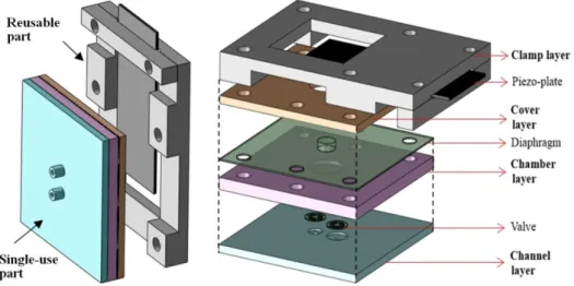
Fig. 2-2 shows the proposed separable piezoelectric micropump. The pump, also known as Series-1 pump, can be separated into two parts, the reusable part and the single-use part. The reusable part contains the actuator and clamp layer, and the single-use part contains every component that may contact with the working fluid. Thus, the risk of contamination and infection can be reduced while the application cost is affordable due to the repeated use of the costly actuator.
Fig. 2-2 Schematic view of the proposed Series-1 separable pump with single-use and reusable part
2.2.1 Bossed Diaphragm
To fulfill the aforementioned requirements of diaphragm in Section 2.1, the present study deviated from conventional flat-type diaphragm designs by employing a cylindrical transfer column diaphragm design. This design is referred to as a “bossed diaphragm.”
Fig. 2-3 Bossed diaphragm with integrated cylindrical transfer column (Ra is the radius
of the pump chamber and Rb is the radius of the column)
As shown in Fig. 2-3, the cylindrical protrusion not only facilitates the contact between the diaphragm and the piezo actuator, but also serves as a rigid center area.
To characterize the diaphragm, the authors defined a dimensionless parameter, called the
“bossed ratio” (Br), to represent the ratio between the radius of the bossed area rb and that of the pump chamber ra (values range between 0 and 1).
𝐵𝑟 =𝑟𝑏
𝑟𝑎 (2-1)
Compared to a flat diaphragm, the bossed diaphragm offers increased stiffness without any modification to the overall thickness of the diaphragm d. According to Eq. (2-2) in Section 2.3.1, the equivalent stiffness will rise with the increasing of the radius of the bossed area rb. In addition, the use of the bossed design reduces wrinkling of the diaphragm during installation, which is a common problem in pumps with flexible diaphragms. It is difficult to avoid any non-uniform stress on diaphragm when clamped between two structures. For a diaphragm with low stiffness, the stress may induce wrinkles and makes an influence on the equivalent stiffness. The behavior of a corrugated diaphragm is different from the original flat diaphragm and the equivalent stiffness may become higher or lower [25], thus increasing the difficulty in predicting the performance of the pump. On the other hand, the bossed diaphragm facilitates the installation. The stiffness can be increased by using the bossed design. Further, the thick central protrusion area can be considered a center rigid area without wrinkles. Thus, the bossed diaphragm can offer the advantages in that it prevents distortion and wrinkling during the installation of the diaphragm. In addition, the size of the protruding column, that is, the bossed area, can be adjusted to enable the easy modification of the operational characteristics of the diaphragm.
The bossed diaphragms also provide some advantages related to the manufacture process.
The previous fabrication of the diaphragm relied on a “thermal-press-forming” machine as shown in Fig. 2-4. The thickness of the diaphragm was controlled by the pressing pressure. It is easier to use previous method, compared to molding process, to produce large but thin diaphragm without the broken of diaphragm during release from the mold.
However, considering the volume change of cooling after released from the mold, it is very hard to control the thickness of the diaphragm. The advantages of the bossed diaphragms include, first, they can be fabricated via molding process because the rigid center area facilitates the release of the diaphragm from the mold. Second, it is easy to control the size of bossed area by the mold structure. Therefore, the easy modification of the operational characteristics of the diaphragm can be achieved by adjusting the bossed area design without change the thickness of diaphragm.
Fig. 2-4 QC601A thermal-press-forming machine (廣錸儀器公司)
2.2.2 Actuator
The actuator is another key component of piezoelectric micropumps. The most common actuators are based on circular piezo discs or rectangular piezo plates. Ma developed a fluid-delivery micropump using a one-side actuating rectangular piezo plate and fully characterized the improved performance attained with the large vibration amplitude of the rectangular bimorph piezo plates. The rectangular actuator was clamped at one end and induced large vibrating on the other side during operating. The rectangular piezo plates have also been used as the actuator of a vibrating fan cooling system [26]. In this design, a PVC blade was pasted on the short edge of piezo plate to increase the vibrating amplitude of the tip. The amplitude of the rectangular piezo actuator is higher than 2mm.
The actuator of the proposed separable micropump is based on the same design.
Fig. 2-5 The rectangular piezo actuator and the clamp layer
As shown in Fig. 2-5, a rectangular piezoelectric plate (Standard Stripe Actuator 402020) measuring 20 × 40 × 0.7 mm is used as the actuator. The maximum deflection of the piezo plate is large than 1.1mm and can be operated with an alternative input lower than 80V.
A PVC blade measuring 20 × 25 × 1 mm is pasted on the short edge of the piezo plate, hence the vibrating amplitude of the tip is increased.
2.2.3 Pump Chamber and Valve
Beneath this plate is a circular pump chamber covered with the bossed diaphragm. The diameter of the pump chamber is 10 mm (𝑟𝑎= 5 𝑚𝑚) and the depth is 0.5, 1 or 1.5 mm.
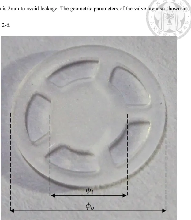
The valve is a key component of micropump which can be sorted as check valve and dynamic valve [27-29]. The valveless micropumps have the advantage of simple structure but often provide a lower pump head compared to pumps with check valves [30, 31]. The bridge type valves are common used in commercial micropumps. Two identical PDMS bridge-type check valves, as shown in Fig. 2-6, are combined with the micropumps in this study. Luo & Ma [32] used this type of valve in a separable piezoelectric pump exhibiting good anti-backflow capability. The valves can be easily clamped between the chamber layer and the channel layer with an o- ring. To avoid breakage of valve during the drafted from the mold, the thickness of the valves in this study is 0.3 mm. The radius of center
area is 2mm to avoid leakage. The geometric parameters of the valve are also shown in Fig. 2-6.
Fig. 2-6 Passive PDMS valve (𝜙𝑖 = 2mm, 𝜙𝑜 = 5.8mm, thickness=0.3 mm)
2.2.4 Fabrication
Fig. 2-7 is a photograph of a fabricated separable pump, Series-1. Both check valves and the diaphragm are manufactured from PDMS. PDMS (SYLGARD 184 silicone elastomer)
is supplied in two parts, specifically, a lot-matched base and a curing agent, which are mixed at a ratio of ten parts base to one part curing agent by weight. PDMS becomes completely solid in molds at 75℃ within 2.5 hours. The molds with the mixture are placed in a vacuum chamber for four hours to remove air bubbles before the heat cure.
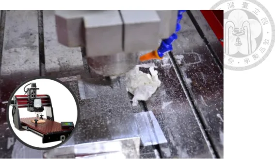
Because the diaphragm molds are fabricated on a highly accurate CNC machine, as shown in Fig. 2-8. It is a 3-axis CNC milling machine and able to achieve 0.01 mm of position with repeatability to 0.005 mm. Because the material of the pump chamber and the molds for valve and diaphragm are PMMA and aluminum, which have no strain hardening effect, it was easy to perform the manufacture without significant of vibration of the machine.
Thus, the dimensions of the fabricated structures could be well controlled. Therefore, by considering the fabrication of the diaphragm, changing the bossed ratio offers a better way of modifying the equivalent stiffness of the diaphragm than changing the thickness.
Several separable piezoelectric micropump with different pump chambers and diaphragms have been manufactured.
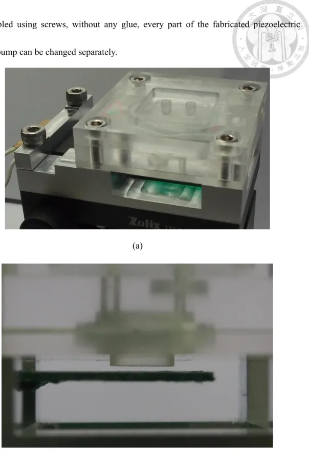
The proposed Series-1 separable micropump consists of four CNC-fabricated PMMA layers with cross section measuring 44 × 44 mm , referred to as the clamp, cover, chamber, and channel layers. The piezo actuator is clamped to the clamp layer, whereas the diaphragm is fixed between the cover layer and the chamber layer. As the layers are
assembled using screws, without any glue, every part of the fabricated piezoelectric micropump can be changed separately.
(a)
(b)
Fig. 2-7 (a) Photograph of the fabricated separable pump, Series-1, and (b) close-up of the actuator and diaphragm assembly
Fig. 2-8 CNC machine for PMMA layers 2.3 Theoretical Analysis
Prior to performance testing, a theoretical analysis was conducted to characterize the micropump. Fig. 2-9 is a force analysis chart of the diaphragm during the suction stage.
In separable pumps, the return action of the diaphragm during the suction stage is not related to the actuator. Rather, the elasticity of the diaphragm and the residual fluid in the pump chamber provide the critical forces that influence the return of the diaphragm to the equilibrium position. The Fe is the elastic force induced by the deflection of diaphragm, and the Fad is the adhesive force act on diaphragm, which is related to the remaining liquid in the chamber after the end of dispensing stage. The valve opening force, Fv, is induced by the pressure difference between the inside and outside of pump chamber. For a specific valve design, a minimum Fv exists to open the valve. If the elastic force is too weak to overcome the influence of adhesive force, the insufficient pressure change will not cause
the open of valve. Thus, the suction of liquid fails and the diaphragm cannot return to the equilibrium position.
Fig. 2-9 Force diagram for a separable piezoelectric micropump during suction stage (Fad is the adhesive force act on the diaphragm. Fe is the elastic force induced by the deflection of diaphragm. Fv is the force required to open the valve. Ra is the radius of
the pump chamber and Rb is the radius of the column)
2.3.1 Elastic Force of Diaphragm
A cylindrical protrusion is used on the Series-1 separable pumps. Because the cylindrical protrusion is at least five times thicker than the surrounding area, the central region is assumed to be a rigid area without any deformation. The diaphragm was assumed to be an elastomer that conforms to Hooke’s law, for which the equivalent stiffness coefficient keff can be expressed as follows [33, 34] :
𝑘𝑒𝑓𝑓 = 2𝜋𝑟𝑏𝐷 𝑟𝑎3(𝐶2𝐿6
𝐶5 − 𝐿3) (2-2)
where
D = 𝐸𝑑3
12(1 − 𝜈2) , (𝑑 = thickness of the silicone rubber) 𝑐2 =1
4[1 − 𝐵𝑟2(1 + 2 ln (1 𝐵𝑟))]
L6 = 𝐵𝑟
4 [𝐵𝑟2− 1 + 2ln𝐵𝑟] C5 =1
2[1 − 𝐵𝑟2] L3 =𝐵𝑟
4 {[𝐵𝑟2+ 1] ln (1
𝐵𝑟) + 𝐵𝑟2− 1}
𝐵𝑟 =𝑟𝑏 𝑟𝑎
Subsequently, the elastic force of diaphragm can be expressed as follows:
𝐹𝑒 = 𝑘𝑒𝑓𝑓× 𝑦𝑐 (2-3)
Where yc represents the displacement of the central region. According to Eq. (2-2) and (2-3), the elastic force is highly affected by the bossed ratio and thickness of diaphragm.
A higher bossed ratio and thickness leads to a higher equivalent stiffness and elastic force.
2.3.2 Adhesive Force Acting on Diaphragm
In this study, the magnitude of the adhesive force, Fad, was theoretically compared under a range of different conditions, in which adhesion resulted from the differences between the upward and downward pressure on the diaphragm; in other words, the difference between the pressure of the fluid acting on the bottom of the diaphragm and the air pressure above the diaphragm. Therefore, the association between the pressure distribution below the diaphragm and the design of the diaphragm was determined.
In this context, a thin-film approximation assumption was used, for which the pressure
distribution in the pump can be expressed as follows [35]:
𝜕𝑝
𝜕𝑟 =6𝜇𝑟 ℎ3
𝑑ℎ 𝑑𝑡+𝑐1
𝑟 (2-4)
The height of residual liquid, h, is a function associated with r. To simplify the system, the rigid central area of the diaphragm was assumed to remain level, and the distance between the bottom of the diaphragm and the bottom of the pump chamber was defined as hc = hp - yc. The surrounding area exhibited a linear change, causing the height of the residual fluid to increase linearly from hc to hp (See Fig. 2-9). Thus, the height of the residual fluid h can be expressed as follows:
h = ℎ𝑐, 𝑟 ≤ 𝑟𝑏 , or h = 𝑟 − 𝑟𝑏
𝑟𝑎− 𝑟𝑏(ℎ𝑝− ℎ𝑐) + ℎ𝑐, 𝑟𝑏 ≤ 𝑟 ≤ 𝑟𝑎 (2-5)
The value of h in Eq. (2-5) is incorporated into Eq. (2-4) and then integrated with r. To obtain p, we assume p = P0 when r = ra.
p = −3μ𝑑ℎ
𝑑𝑡
(𝑟𝑎−𝑟𝑏)3(𝑟𝑎ℎ𝑐−𝑟𝑏ℎ𝑝+2𝑟(ℎ𝑝−ℎ𝑐)) (ℎ𝑝−ℎ𝑐)2(𝑟𝑎ℎ𝑐−𝑟𝑏ℎ𝑝+𝑟(ℎ𝑝−ℎ𝑐))2
+ 𝐷1, 𝑟𝑏≤ 𝑟 ≤ 𝑟𝑎 , or
p = 3μ𝑑ℎ 𝑑𝑡
𝑟2
ℎ𝑐3 + 𝐷2, 𝑟 ≤ 𝑟𝑏 (2-6) where
𝐷1 = 𝑃0− 3𝜇𝑑ℎ 𝑑𝑡
(𝑟𝑎− 𝑟𝑏)(𝑟𝑎ℎ𝑐− 2𝑟𝑎ℎ𝑝+ 𝑟𝑏ℎ𝑝) ℎ𝑝2(ℎ𝑝− ℎ𝑐)2
𝐷2 = 𝑃0− 3𝜇𝑑ℎ 𝑑𝑡{𝑏2
ℎ𝑐3 + 𝑟𝑎− 𝑟𝑏
(ℎ𝑝− ℎ𝑐)2[(𝑟𝑎ℎ𝑐 − 2𝑟𝑏ℎ𝑐 + 𝑟𝑏ℎ𝑝) ℎ𝑐2
+(𝑟𝑎ℎ𝑐 − 2𝑟𝑎ℎ𝑝+ 𝑟𝑏ℎ𝑝)
ℎ𝑝2 ]}
The adhesive force can be calculated once p has been obtained, and the value of Fad can be obtained as follows:
𝐹𝑎𝑑 = ∫ ∫ (𝑝 − 𝑃0)𝑟 𝑑𝑟 𝑑𝜃
𝑎
0 2𝜋
0
(2-7) which can be simplified to
𝐹𝑎𝑑 = −6𝜋𝜇𝑑ℎ
𝑑𝑡𝐶𝑎𝑑 (2-8)
where
𝐶𝑎𝑑 = [{− 1
(ℎ𝑝− ℎ𝑐)4(𝑟𝑎− 𝑟𝑏)3[ (𝑟𝑎ℎ𝑐 − 𝑟𝑏ℎ𝑝)2 𝑟𝑎ℎ𝑐 − 𝑟𝑏ℎ𝑝+ 𝑟(ℎ𝑝− ℎ𝑐)
+ 3(𝑟𝑎ℎ𝑐 − 𝑟𝑏ℎ𝑝) ln[𝑟𝑎ℎ𝑐− 𝑟𝑏ℎ𝑝+ 𝑟(ℎ𝑝− ℎ𝑐)] − 2𝑟𝑎ℎ𝑐
+ 2𝑟𝑏ℎ𝑝+ 2ℎ𝑐𝑟 − 2ℎ𝑝𝑟]}|
𝑟𝑏 𝑟𝑎
+1 2𝛼𝑟2|
0 𝑟𝑏
− 1𝑟4 4ℎ𝑐3|
0 𝑟𝑏
+1𝛽𝑟2 2 |
0 𝑟𝑏
]
α =(𝑟𝑎− 𝑟𝑏)(𝑟𝑎ℎ𝑐− 2𝑟𝑎ℎ𝑝+ 𝑟𝑏ℎ𝑝) ℎ𝑝2(ℎ𝑝− ℎ𝑐)2
β = 𝑟𝑏2
ℎ𝑐3+ 𝑟𝑎− 𝑟𝑏
(ℎ𝑝− ℎ𝑐)2[𝑟𝑎ℎ𝑐+ 𝑟𝑏ℎ𝑝− 2𝑟𝑏ℎ𝑐
ℎ𝑐2 +𝑟𝑎ℎ𝑐 − 2𝑟𝑎ℎ𝑝+ 𝑟𝑏ℎ𝑝
ℎ𝑝2 ]
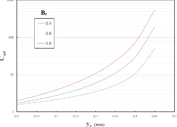
where dh/dt is associated with the velocity of the diaphragm (increasing the frequency requires a larger dh/dt to enable the diaphragm to rapidly return to equilibrium), and Cad, the adhesive force coefficient, is associated with the design of the pump chamber and diaphragm. The values of Cad with different bossed ratios and displacement are shown in Fig. 2-10. The calculation is based on pump with the 0.5-mm chamber depth and 5-mm chamber radius. The y- axis is logarithmic and the Cad expands rapidly when the value of yc is near the depth of the pump chamber. Subsequently, for a constant amplitude, an increase in the bossed ratio produces larger Cad values. Although a large displacement, yc, may lead to a higher stroke volume, it may enhance the influence of adhesive forces acting
on the diaphragm, resulting in failure. Moreover, because the theoretical velocity dh/dt increases with the frequency, the impact of the adhesive force is more pronounced at higher frequencies.
Fig. 2-10 Cad with different bossed ratios and displacement of the center of diaphragm, yc. (hp = 0.5 mm)
2.3.3 The Piezoelectric Theorem
The first demonstration of the direct piezoelectric effect was in 1880 by the brothers Pierre Curie and Jacques Curie. They combined their knowledge of pyroelectricity with their understanding of the underlying crystal structures that gave rise to pyroelectricity to
Br
predict crystal behavior. They found if an electric field is applied to a specific crystal, the shape of the crystal can be changed. It means the electric energy can be changed to mechanical energy. On the contrary, if an external force is applied to the crystal to change its shape, an electric field will be generated inside the crystal, which implies the transforming from the mechanical to electric energy.
The reason is the structure of the specific crystal contains the electric charged parts, electric dipole moments, which may be moved due to the external force, as shown in Fig.
2-11. If a subject has a movable electric dipole moments and the crystal structure of the subject is non-centrosymmetric, the positive and negative electric charges will not be neutralized, leading to the transforming between the electric and mechanical energy. The transforming is the basic of the piezoelectric effect.
Fig. 2-11 The deformation of the lattice and the displacement of the dipoles The piezoelectric effects can be classified into dielectric piezoelectric effect and converse piezoelectric effect, as shown in Fig. 2-12. The dielectric piezoelectric effect performs
when the structure is changed due to an external force. The mechanical energy will be transformed to electric energy, resulting in an internal electric field inside the crystal. On the other hand, the converse piezoelectric effect, transforming energy from electric to mechanical type, occurs when an electric field applied on the crystal. Because the deformation of the crystal can be controlled by the electric field. Thus, if an alternating electric field can be applied on the piezoelectric material, the material will periodically shrink and expand following the change of electric field. It generates the vibration of the piezoelectric material, which can be further used as an actuator.
Fig. 2-12 piezoelectric and converse piezoelectric effects [36]
Applying pressure to the piezoelectric material, the electric dipole will be shorten due to the compression of the material. To resist the change and retain the original structure, equal positive and negative electric will be induced on the opposite surface of the material, which are named as polarized surface. The electric charge density displacement, De, is proportional to the external electric field, Ee.
𝐷𝑒 = ε ∙ 𝐸𝑒 (2-9) ε is the dielectric constant. The electric field will disappear after the pressure is eliminated.
Moreover, the polarity of the surface can be changed according to the direction of the pressure. The effect is named as dielectric piezoelectric effect.
The electric dipole can be elongated to a specific direction to resist the change when an electric field is applied to the piezoelectric material. The relationship of the strain (S) and external electric field Ee can be derived as,
𝑆 = 𝑑𝑡 ∙ 𝐸𝑒 (2-10)
Dt is the piezoelectric constant. The electric dipole will return to its original shape without deformation after the external electric field is eliminated. The effect is named as converse piezoelectric effect.
The electric dipole moment and the stress equation can be coupled together, as shown below,
(2-11)
(2-12)
The common materials that exhibit the piezoelectricity include quartz, berlinite (AlPO4), sucrose (table sugar) and many kinds of synthetic crystal or ceramic materials, such as lithium tantalate (LiTaO3), barium titanate and lead zirconate titanate. Lead zirconate titanate (Pb[ZrxTi1−x]O3 with 0 ≤ x ≤ 1), which is also called as PZT, is the most common piezoelectric ceramic in use today. This is also the material we used in this study.
The piezoelectric actuator can be also classified by their operation type. The major types include vibrate, axial and radial deformation (Fig. 2-13). A bimorph vibrating actuator is used in this study, as shown in Fig. 2-14. The applied actuating electric energy, an alternative current, can generate an alternative electric field along the transverse direction of the piezoelectric plate, resulting the periodic deformation of the plate along the longitude side. The major influence parameter of the vibrating amplitude is the coefficient
d31, according to the electric dipole and strain relationship function (2-12). Because the bimorph vibrating actuator has inverse coefficients on two sides of the plate, two identical electric fields will induce contrary deformations. For instance, if the top layer increase its length due to the electric field, the bottom layer will decrease its length simultaneously.
The contrary deformations can lead to the deflection of the bimorph actuator if the
boundary between the two layers is fixed without relative movement. Hence, the alternative current can induce periodic vibrating of the actuator plate.
Fig. 2-13 The major operation types of piezoelectric actuators [37]
Fig. 2-14 Bimorph vibrating piezoelectric actuator [37]
A common bimorph vibrating piezoelectric actuator has nine sub- layers, but it’s also acceptable to dispense one or two sub- layers to simplify the design for specific applications. However, the elimination of the sub- layers often lead to a poor performance of the actuator.
In general, the vibrating amplitude of bimorph piezoelectric plates with similar design is proportional to the actuating voltage and the square length of the plate but it’s inverse proportional to thickness of the actuator plate. The relative equation is shown below, where the kpzt is the bimorph vibrating coefficient, tpzt is the thickness and V is the applied actuating voltage.
𝛿𝑝𝑧𝑡 = 𝑘𝑝𝑧𝑡× (𝐿𝑝𝑧𝑡
𝑡𝑝𝑧𝑡)2× 𝑉 (2-13)
Compared to single-layer vibrating piezoelectric actuator, the response under of a bimorph design under different frequencies can be influenced by the adhering method and material, and the thickness and material of each layer. It is impossible to analyze the frequency response by a single equation. The major advantage of the bimorph vibrating actuator is the vibrating performance. The bimorph design can provide the same vibrating amplitude as a single-layer actuator while the required actuating voltage of bimorph design is only half of what of single-layer design. Thus, its applicability is better than the single-layer design.
All actuators implemented in this study are bimorph PZT actuator plates.
2.4 Experiments2.4.1 Set-up of the Performance Test
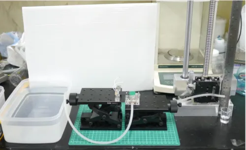
Fig. 2-15 shows the experimental set-up for testing the performance of the series-1 pumps.
The pump and the piezo plate are driven by an alternating sine-wave voltage ranging from 50 to 80 V with a frequency of less than 20 Hz. The signal waves and frequencies are controlled by a function generator. An amplifier is needed to modulate the voltage to a required value. To measure the flow rates, two tubes, 1.5 mm in diameter are attached to the inlet and outlet. The flow rates can be estimated by measuring the velocity of the fluid in the outlet tube. The height difference between the inlet and outlet tubes, H, represents
the pump heads of the pump. Data are recorded every 5 Hz to enable the analysis of the pump performance with different diaphragms and pump chambers. Moreover, a high speed camera, X- stream XS- 4, is used to measure yc, the displacement of the diaphragm, by observing the motion of the central protrusion area of bossed diaphragm.
Fig. 2-15 Experimental set-up for Series-1 separable pumps
Fig. 2-16 Experiment set-up of the backpressure versus flow rate tests
2.4.2 Instruments Used in the Experiments
The instruments used in these experiments include function generator, power amplifier, high speed camera, torque wrench and large scale and precision lifting platforms.
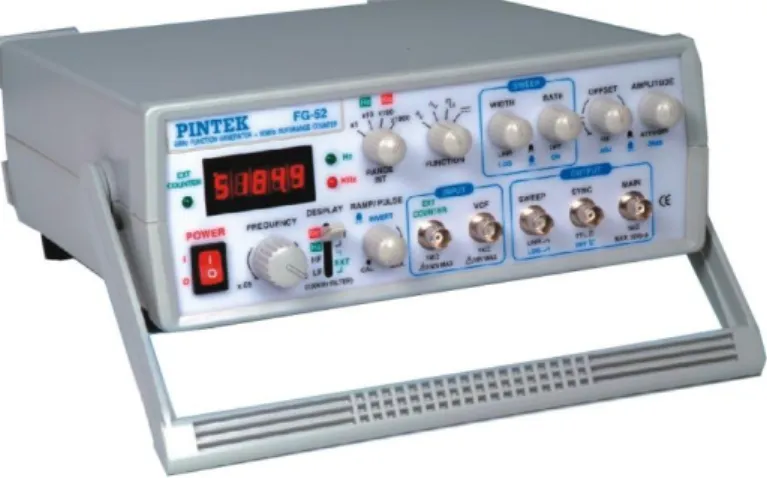
Function generator
The PINTEK FG-52 is a low frequency function generator. The input of the function generator is 110Vrms alternative source and the output is a programmable signal that can adjust the waveform, voltage and frequency. Though the user interface is analog, the information of the waveform, voltage and frequency can be shown on the front panel.
(Fig. 2-17) The function generator can generate sine, triangle, step or pulse waves and the output voltage can be adjusted from 0 to 10Vp-p under 50 ohm output load. There are 8 frequency ranges can be specified. The frequency range of the sine wave is from 0.5 to 50 Hz if the “× 10 Hz” range is used and the resolution of the frequency is 0.001Hz. The sine waves are used to produce periodic vibration of the piezoelectric actuator plate.
Fig. 2-17 Low frequency function generator, Pintek FG-52
Power amplifier
The power amplifier is required to increase the voltage of the actuating signal. The A-303 amplifier by A.A.Lab was used in the experiments. (Fig. 2-18) It can increase the voltage of the input signal from 1 to 20 times and the maximum voltage of the output voltage can be 400Vp-p and the maximum power output is 40 watts. The effective input signal range is DC to 450 kHz and the amplitude should be lower than 24Vp-p.
Fig. 2-18 Power amplifier, A-300 by AA. Lab
Torque wrench
A Tohnichi 15DB4 is used to control the torque during assembling each layer of the separable pumps. (Fig. 2-19) The measurement range is from 2 to 15 kgf.cm and the minimum scale is 0.2 kgf.cm with 3% of accuracy within the measurement range.
Fig. 2-19 Tohnichi 15DB4 torque wrench
Large scale lifting platform
The platform, as shown in Fig. 2-20, is designed by our team. A screw is used to control the height of the sliding block. In the backpressure-flow rate experiment, the outlet tube of the pump is clamped on the sliding block. Thus, adjustment of the backpressure can be easily achieved by changing the height of the block.
Fig. 2-20 Large scale lifting platform
Precision lifting platform
Precision platform, TSMV-60-1S and TSMV13-1A is used to control the relative distance between the piezoelectric actuator plate and the diaphragm of the pump. The actuator is controlled to be slightly touched with the diaphragm. The precision lifting platform can provide a 60-mm (TSMV-60) or 13-mm (TSMV13) maximum movement. (Fig. 2-21) The piezoelectric plate is clamped on the platform by a clamper fabricated by the precision CNC machine.
Fig. 2-21 Precision lifting platform by 先鋒科技
High speed camera
The XS-4 high speed camera, as shown in Fig. 2-22, is used to measure the
displacement of the diaphragm and actuator. A 4000 frame rates was used to record the vibrating of the piezoelectric plate to avoid aliasing effect and missing of the photo of maximum vibrating amplitude. Multiple lights are required for capturing clear video
because of the short exposure time of each frame resulting from the high speed video mode.
Fig. 2-22 High speed camera
2.4.3 Tested Pumps
Several parameters have been tested in this part of the study to evaluate the influence and try to optimize the performance of the proposed separable pumps under the restrictions of the pump chamber size. The study is a part of the MOEA project to develop micropumps for a portable PCA, patient controlled anesthesia, system. Thus, the chamber size of Series-1 must be compatible to other structure of the whole system. As a result under restrictions, the radius of the pump chamber is 5 mm and the distance between the actuator and the diaphragm is 0.3 mm. The depth of the pump and diaphragm design including the bossed ratio and thickness are the parameters tested and discussed in the experiment. The parameters of the fabricated separable piezoelectric pumps are listed in
Table 2-1. The operating voltage is lower than 80V to avoid piezo plate cracking and the frequency is lower than 20 Hz to fulfill the medical requirements. The operating frequencies of common portable infusion pumps, such as PEGASUS infusion pumps, are lower than 15 Hz. Code names from Pump A to E are used to facilitate the discussion in the following sections.
Table 2-1 Parameters of the Series-1 separable piezoelectric pump
Code name Radius of pump chamber, ra (mm)
Depth of pump chamber, hp (mm)
Diaphragm thickness, d (mm)
Bossed ratio, Br
Pump A 5 1.5 0.4 0.7
Pump B 5 1 0.4 0.7
Pump C 5 0.5 0.4 0.7
Pump D 5 1 0.2 0.7
Pump E 5 1 0.3 0.3- 0.8
2.5 Results and Discussion of the Experiments 2.5.1 Effect of Pump Chamber Depth on Flow Rates
Changing the depth of the pump chamber may have a significant influence on the pump performance. The compression ratio is the ratio of the stroke volume to the dead volume.
In our previous experiences on PZT micropump, a higher compression ratio results in a better pumping performance [19]. To analyze the influence of the chamber depth, Pump A, B and C of Series-1 were tested. The diaphragms are 0.4 mm with the bossed ratio of
0.7. Fig. 2-23 compares the flow rates of Pump A, B and C at 50 V for different frequencies. Obviously, the flow rate of the pump with the 1-mm chamber depth, Pump B, is greater than the pump with a 1.5-mm chamber depth, Pump A. The flow rates for Pump B can be 1.35 ml/min at a frequency of 10 Hz, while this becomes 1.12 ml/min for Pump A. The higher flow rate may be a result of the increase in the compression ratio.
Table 2-2 The calculated values of Fe and Fad with different designs (measured at 50 V and 10 Hz)
yc (mm) hc (mm) Fe (N) Fad (N) Fad/Fe
Pump A 0.46 1.06 2.11 × 10⁻² 6.22 × 10⁻⁵ < 0.01 Pump B 0.47 0.55 2.16 × 10⁻² 3.72 × 10⁻⁴ 0.017 Pump C 0.37 0.13 1.7 × 10⁻² 1.31 × 10⁻² 0.771 Pump D 0.67 0.33 3.84 × 10⁻³ 1.61 × 10⁻³ 0.419 Pump E
(Br =0.7) 0.56 0.44 1.08 × 10⁻² 6.73 × 10⁻⁴ 0.063
Table 2-2 compares the displacements, yc, of each design at 50V. We can assume that the stroke volume for Pump A and B are similar owing to the pump diaphragm design being identical in both cases. Thus, compared to Pump A, a higher compression ratio can be achieved with Pump B due to the smaller chamber volume and thus produces the better performance. The ability of a pump to self-prime and tolerate bubbles is also markedly influenced by the compression ratio. Because of the high compressibility of air, a large compression ratio is necessary to reach the minimum valve opening pressure. The effect
of the chamber depth on the ability of the pump to self-prime was observed in the experiments. Self-priming is easily achieved by Pump A; the self-priming ability is negligible when the pump chamber is deeper than 2 mm.
Although a thin pump chamber, relative to deep one, can provide a higher compression ratio, the pump performance may not be enhanced. According to Table 2-2, the value of adhesive force in Pump C is close to the value of elastic force. We can assume that the return of diaphragm is strongly influenced. Thus, compared to Pump A and B, the flow rate for Pump C is lower and difficult to predict.
Fig. 2-23 Measured flow rate with different chamber depths at different frequencies (under ± 50 V)


![Fig. 2-12 piezoelectric and converse piezoelectric effects [36]](https://thumb-ap.123doks.com/thumbv2/9libinfo/9603579.629914/44.892.178.717.565.823/fig-piezoelectric-converse-piezoelectric-effects.webp)