國立臺灣大學工學院材料科學與工程學研究所 碩士論文
Department of Materials Science and Engineering College of Engineering
National Taiwan University Master Thesis
高強度含銅雙相鋼銅顆粒及奈米碳化物雙析出行為之 穿透式電子顯微鏡分析研究
TEM Investigation on the Dual Precipitation Behavior of Nanometer-sized Carbides and Copper Precipitates in
High Strength Copper-Bearing Dual-Phase Steels
李承翰 Cheng-Han Li
指導教授:楊哲人 博士 Advisor: Jer-Ren Yang, Ph.D.
中華民國 105 年 7 月
July, 2016
誌謝
轉眼之間兩年的碩士班生涯就這樣結束了,這些日子來,多虧有身旁的朋友 們及師長的鼓勵與相助,我才能順利地完成這本論文。
首先我要感謝我的指導教授-楊哲人老師,楊老師在我的研究上和人生的規 劃上給予我許多的幫助與建議,從大二的物理冶金開始,啟發了我對鋼鐵研究的 興趣。老師除了提供實驗室不虞匱乏的研究資源外,也給予我們自由的研究風 氣,讓我們能徜徉在材料研究的世界裡,探索自然的真諦。除此之外,老師對學 生的關心與鼓勵,使我們在面臨瓶頸時,能重新思索、面對問題,進而想出辦法 解決。這些日子很感謝恩師楊老師的照顧,使我的研究能順利地完成。
感謝中鋼的陳茂村先生,除了幫助我完成重要的實驗外,也在人生的哲理上 與我分享許多故事與建議,以及待人處事的方法和態度,使我每次去中鋼做實驗 時都如醍醐灌頂般的受益良多,並能重新檢視自我。
感謝電子顯微鏡技術員陳學人先生,在對電子顯微鏡的愛護以及對學生們的 照顧及訓導,使我們在操作電子顯微鏡能很順利地完成自己的研究。
感謝顯微結構設計實驗室的顏鴻威老師,顏老師在相變態實驗室博士班時的 研究是我們的楷模,如同燈塔一般使我們在研究上能找到學習的方向。此外,顏 老師對研究孜孜不倦的熱誠,也成為我們後生晚輩最佳的典範。同時,亦師亦友 的顏老師也對我們非常的照顧,兩年來非常感謝您的幫助。
感謝系辦的林由莉小姐、呂碧玲小姐、張瑛梅小姐、周麗美小姐這兩年來的 幫助,處理實驗室及系上的大小事,也提點我的疏漏。
感謝實驗室的大師兄黃柏銘博士,從我大三時就帶著我做研究,並在碩士班 研究上的給予我諸多幫助與建議。柏銘學長帶給實驗室的黃金十年,從實驗室設 備的購買到維護,從研究技術的發明到傳承,無一不是實驗室成長茁壯的基石,
如同宇庭學長說的:「每個實驗室,都應該要有一個黃柏銘」。感謝張雅齡博士,
耐心的教導學弟妹們電子顯微鏡,以及處理實驗室的大小事,還有對學弟妹的關
心與照顧,帶個實驗室滿滿的溫暖。感謝陳伯宇博士,在實驗室的付出與貢獻,
以及對學弟妹的指導和鼓勵。感謝蔡宇庭博士,優異的研究成果及電子顯微鏡操 作技巧成為我們學習的對象,以及不時給予學弟妹的指導,宇庭學長撰寫的中鋼 專書也成為實驗室重要的資產。感謝雙相鋼研究小組的司令官蔡劭璞學長,一說 到此,我感激的淚水就如同滔滔江水連綿不絕,即使學長自己忙於大聯盟的計劃 以及諸多研究報告,仍然花許多時間指導我們的研究,從研究的設計,到遇到難
題的解決,都給了我們數不盡的幫助。感謝陳昱文學長,在TEM 上的協助,以
及對實驗室的諸多貢獻,同時也是實驗室的開心果,帶給實驗室歡樂的氣氛,同 時以身作則向學長學習的態度,也讓我受益良多。感謝鍾采甫學長,對研究及課 業的積極是我們一直努力學習的對象,也同時在生活上對我們很照顧,時時提點 我們。感謝相變態學術研討團隊(Phase Transformation Assassins)的成員們(昱文、
亦傑、博彥、國瑞、啟任及致睿),在課後一起對研究的討論及培養團隊合作的 能力。感謝鄭至閎學長,有耐心地在陪同我做實驗以及作為我對雙相鋼研究的楷 模,讓我不勝感激,除此之外,也用有深度的笑話帶給實驗室滿滿的歡笑。感謝 謝亦傑學長及童博彥學長,對我們的照顧及提攜,陪伴我們煎熬的研究生生活。
感謝啟任和致睿在這兩年來一起努力、一起在實驗室奮鬥、一起看實驗室的日 出、一起聽王啟任唱歌、一起向甫甫看齊,沒有你們,就沒有今天的我,感謝你 們這些日子來的陪伴。感謝實驗室的學弟妹,沛衡、世寧、世雯、俊霖,以及 r05 的學弟妹,一起分攤實驗室的大小事,你們是實驗室的生力軍,未來是你們 的。
感謝好鄰居顯微結構設計實驗室的冠儒、雪莉、俊德、世哲、孟軒、昱辰、
正堯。感謝所有台大材料系b99 的夥伴們,這六年來一直受到你們的照顧。感謝
鵬仁時時提醒我,要考GRE、托福、時時關心我的研究。感謝這兩年來認識的所
有朋友,多虧有你們我才能順利地走到這一刻。
感謝口試委員顏鴻威老師、熊樂群老師、黃慶淵博士、陳志遠博士對於我論
文的耐心指導,給予我十分重要的建議及提點我的缺失,使我論文能順利的完 成。
感謝豐如和柯基咚咚還有史努比,謝謝你們的陪伴,成為我挫折氣餒時的動 力,也作為我的精神支柱。
最後我要感謝我的家人,默默的幫助我、關心我,一直以來你們都讓我很自 由的選擇我的未來,也相信我能做到我想做到的事情。感謝我的父親,公事繁忙 卻仍要一肩扛起家裡的大小事。感謝我的母親,從小對我嚴厲的教導,讓我能時 時警惕自己,如今,我已然完成人生一個重要的里程碑,在此獻給在遠方的您。
感謝這兩年來的點點滴滴,能夠完成這篇論文,受之於人者太多,出之於己 者太少。完成並不是結束,而是另一個新的旅程的開始,期許自己將來能奉獻所 學,造福社會。
論文摘要
近年來為了降低溫室氣體二氧化碳的排放,在同時改善次世代汽車用鋼的能 耗需求,以及考量良好的穩定性及安全性的條件下,輕量化先進高強度鋼的開發 在汽車工業上扮演極為重要角色。而其中雙相鋼由於良好的強度和成形性,早在 二十世紀末就已經商業化的大量生產。因此,現今雙相鋼已大量用於汽車工業 上。除此之外,近年來在環保的意識抬頭下,銅元素在鋼鐵中的影響逐漸受到重 視。在鋼鐵的生產過程中,廢鋼的添加是現今鋼材重要的一環,由於銅元素為廢 鋼中主要的微合金元素之一,因此,在經濟及環保的考量下,高強度鋼含銅鋼的 開發是極具有吸引力的。
本研究引入界面析出合金碳化物以及奈米銅顆粒析出的概念,來同時強化雙 相鋼中肥粒鐵與麻田散鐵,並藉此降低兩相之間的強度差距以提升雙相鋼的成形 性。並且利用穿透式電子顯微鏡來分析碳化物及奈米銅顆粒在低碳雙相鋼中雙析 出的現象以及分析高溫時效處理對其硬度的影響。
本研究除了對於雙相鋼硬度的提升外,也利用掃描穿隧電子顯微鏡的環形暗 場技術進行顯微結構的觀察,並搭配能譜分析儀(EDS)分析合金元素的分布,進 而探討在雙相中二次強化的機制。此外,雙相鋼整體的機械性能也透過拉伸試驗 來分析時效前後的性質變化。特別的是,除了雙相鋼的降伏強度及抗拉強度有大 幅的提升外,延性也能透過時效處理的方式而增加。然而,由於兩階段的淬回火 熱處理製程會大幅提升生產成本,因此若能透過在盤捲製程中鋼帶中的殘留溫度 來達成如同時效處理的強化效果,便能使含銅雙相鋼的生產更節能且更有效率。
因此本研究亦利用一系列的模擬盤捲製程來比較其與時效處理的差異。
此外,本研究發現,奈米界面析出碳化物能作為奈米銅顆粒析出的有效成核 位置,因此能使最佳的時效時間提前。本研究嘗試透過發展新的材料設計以達到 優異的機械性能,並期許能引起工業應用及科學研究的興趣。
關鍵詞:雙相鋼,含銅鋼,界面析出物,雙析出,時效硬化,穿透式電子顯微鏡
Abstract
For the sake of reducing the CO2 emission and improving for the efficiency of fuel consumption in the next generation of vehicles, light-weight design for advanced high- strength steels (AHSSs) as well as requirements for durability and safety play an important role in automotive industries in recent years. Dual-phase (DP) steels as one type of AHSSs commercialized by the end of 20th demonstrate special mechanical properties with combination of good strength and formability. Therefore, DP steels have been widely implemented in automotive industries. In addition, with increasing
environmental consideration, copper has called lots of attentions as a part of residual elements contained in recycling steel scraps for producing considerable amounts of commercial steels. Therefore, the development of Cu bearing high-strength steels with better mechanical properties is very attractive from both the economic and
environmental points of view.
In the thesis, the concept of interphase precipitation of alloyed carbide with copper precipitation is introduced in ferrite and martensite to reduce the strength mismatch and improve the strength and formability in DP steels. The objective of the present work is to clarify the effect of dual precipitation of interphase precipitation and nanometer-sized copper particles in a low carbon Cu-Ti-bearing dual-phase steel and to investigate hardness evolution with the effect of aging treatment at elevated temperature.
Besides the enhancement in hardness of both phases, the dual precipitation effects of interphase-precipitated carbide and copper particle with microstructure evolution are identified with the aid of TEM. With imaging techniques of STEM ADF with EDS mapping methods, the mechanisms for secondary hardening in both phases are
elucidated. Furthermore, tensile test is carried out to investigate the overall mechanical properties of the DP steels with or without aging treatment. Surprisingly, not only the yield strength and the tensile strength are enhanced, the ductility is also improved by the treatment of aging. However, owing to the two-step heat treatment of quench-tempering resulting in higher cost of production, it would be more effective and energy-saving if the aging treatment has been finished during the coiling process with the residual temperature of the coil. As a result, a series of simulated coiling process is conducted to compare with the results of aging treatment.
From the present work, the nano-sized interphase-precipitated carbides have been found to serve as effective nucleation site for copper particles and thus shift the peak aging ahead. This research attempts to design a new material with superior mechanical properties with great interest both for industrial application and scientific research.
Keywords: Dual-phase steel; Copper-bearing Steel; Interphase precipitation; Dual precipitation; Aging hardening; Transmission electron microscope
Content
Figure Content ... XI Table Content ... XX
Chapter 1 General Introduction ... 1
Chapter 2 Literature Review ... 4
2.1 Introduction of Dual-Phase Steels ... 4
2.1.1 Brief History of Dual-Phase Steel ... 5
2.1.2 Advanced High Strength Steels ... 7
2.1.3 Heat Treatment and Effect of Alloying Element ... 9
2.1.4 Mechanical Properties of Dual-Phase Steels ... 11
2.1.5 Inhomogeneous Deformation Behaviors of Dual Phase Steels ... 14
2.1.6 Improvement in Formability of Dual Phase Steels ... 16
2.1.7 Effect of Tempering on Dual Phase Steels ... 18
2.2 Introduction of Copper Bearing Steels ... 26
2.2.1 Effects of Copper Addition in Alloyed Steels ... 27
2.2.2 Temporal Evolution of Copper Precipitation ... 29
2.2.3 Strengthening Mechanism of Copper Precipitation ... 32
2.3 Interphase Precipitation in Alloyed Steels ... 40
2.3.1 Morphology of Interphase Precipitation ... 41
2.3.2 Mechanisms of Interphase Precipitation... 41
2.3.3 Strengthening Mechanism of Interphase-precipitated Carbides ... 45
2.3.4 Effect of Interphase Precipitation on the Mechanical Properties ... 49
2.3.5 Dual Phase Steels with Interphase-precipitated Carbides ... 50
Chapter 3 Experimental Procedures ... 59
3.1 Alloy Design and Specimen Preparation ... 59
3.2 Optical Metallography Observation ... 62
3.3 Hardness and Tensile Test... 63
3.4 TEM observation and Analysis ... 65
Chapter 4 Experimental Results and Discussion ... 66
4.1 Heat Treatments for Dual Phase Microstructure ... 66
4.2 Microstructure and Hardness Evolution in Aging Treatment ... 72
4.2.1 Macroscopic Structure in the Ferrite and Martensite ... 72
4.2.2 Vickers Hardness Evolution During Aging Treatment ... 73
4.2.3 Effect of Holding Temperature in Two Phase (α+γ) Region ... 74
4.2.4 Role of Cu during aging treatment ... 76
4.2.5 Role of Ti during aging treatment... 78
4.3 Microstructure Investigation with Transmission Electron Microscope ... 93
4.3.1 TEM Micrograph ... 93
4.3.2 STEM Image and Energy Dispersive Spectrum Mapping ... 95
4.3.3 High Resolution TEM Image of Interphase-Precipitation ... 97
4.3.4 High Resolution TEM Image of 9R Structure of Copper ... 99
4.4 Mechanical Properties of Tensile Test ... 121
4.5 Vickers Hardness Evolution During Simulated Coiling Process... 133
Chapter 5 Conclusion ... 140
Chapter 6 Future Work ... 142
Reference ... 143
Figure Content
Figure 2-1 The typical microstructure of dual-phase steels. The grain of bright contrast is the polygonal ferrite phase and the grain of dark contrast is the martensite phase. ... 21 Figure 2-2 Strength-ductility relationship of dual phase steels compared with that for
plain carbon and HSLA steels. The dual phase steel curve is far above that for ferrite-pearlite steels[24]. ... 21 Figure 2-3 PNGV-Class body structure steel/grade distribution of ULSAB-AVC[1]. ... 22 Figure 2-4 Schematic representation of heat treatments of dual phase steel[24]. ... 22 Figure 2-5 (a) Schematic stress-strain curve. (b) strain hardening rate-strain curve for
dual phase steels (GM980X), HSLA (SAE950X and SAE980X) and plain carbon steel[24]. Relative low yield strength to ultimate tensile strength ratio and continuous yielding of dual phase steel are shown in (a) and high initial strain hardening rate of dual phase steel is presented in (b)... 23 Figure 2-6 Bright field transmission electron microscopic image of the dual-phase steel
showing two ferritic grains (F) separated by martensitic regions (M). The dislocation density near the ferrite/martensite phase boundary is higher than in the interior of the grains[35]. ... 24 Figure 2-7 Jaoul-Crussard plot for the C-Mn-Si dual-phase steel showing points at
which dislocation structures were studied[34]. ... 24 Figure 2-8 Features and mechanisms of damage initiation and propagation in DP
steel[53]. ... 25
Figure 2-9 Influence of microstructures on the hole expansion ratio[53]. ... 25 Figure 2-10 Effect of tempering temperature on strength characteristics (YS, TS, and
YS/TS ratio) of 0.08C–2.1Mn–0.7Si–Mo DP steel [62]. ... 25 Figure 2-11 Phase diagram of iron-copper system[73]. ... 34 Figure 2-12 (a) HAADF-STEM image of bcc Cu precipitates. (b) and (c) are FFT
patterns of the selected areas 1 and 2 in (a), respectively[22]. ... 35 Figure 2-13 Multiply twinned 9R precipitate in Fe-Cu aged for 100 h at 550°C. The
three-layer periodicity of the herring-bone fringe pattern is clearly resolved.
A step is present in the intervariant boundary between two twin-related segments, as indicated by the arrows [100]. ... 35 Figure 2-14 (a) HRTEM image of a 9R Cu precipitate contains a twin band. (b)
Schematic feature of (a). (c) A 9R Cu precipitate showing a perfect 9R stacking ... 36 Figure 2-15 (a) Diffraction Pattern of twinned 9R-Cu precipitate in the ferrite after
aging at 650°C for 30min, and (b) schematic representation of (a). The incident beam was aligned to [111] direction of ferrite matrix[16]. ... 37 Figure 2-16 Transformation mechanism of 9R to twinned fcc Cu[22]. ... 38 Figure 2-17 Transformation sequences of Cu precipitates in ferrite matrix[22]. ... 38 Figure 2-18 The evolution of mechanical property parameters as a function of aging
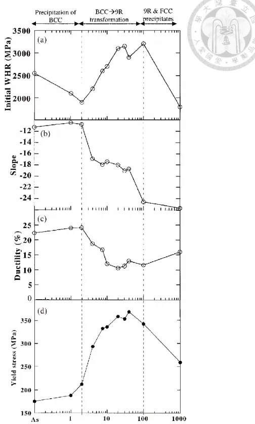
time in copper-bearing steel, (a) initial work hardening rate, (b) slope of the work hardening rate vs. stress, (c) the ductility in tension and (d) yield stress[65]. ... 39
Figure 2-19 TEM image of interphase-precipitated carbides arranged in parallel sheets in the ferrite matrix (Fe-0.15C-0.75V)[107-109]. ... 52 Figure 2-20 Schematic representation of interphase precipitation[113]: (a) γ/α interphase boundary forms; (b) carbides nucleate on interphase boundary; (c) carbides growth and progress of γ/α interphase; (d) carbides nucleate on new
interphase boundary ... 52 Figure 2-21 TEM image of three types of interphase precipitation[115]. (a) irregular CIP
carbides, (b) regular CIP carbides, (c) a mixture of PIP and regular CIP carbides, and (d) PIP carbides. ... 53 Figure 2-22 Schematic model of the formation of interphase precipitation. (a)
Partitioning of carbon from ferrite to austenite, resulting in a gradual build- up. (b) Carbide precipitates nucleate on the ferrite side of γ/α phase
boundary due to the sufficient carbon concentrations and the carbides pin the boundary and depletes the carbon concentration in the adjacent austenite. (c) The carbon depletion increases the driving force for s
migration of γ/α phase boundary and the partitioning process reoccurs[112].
... 54 Figure 2-23 Schematic diagrams illustrating the three mechanism of interphase
precipitation. (a) PIP by ledge mechanism, (b) irregular CIP by bowing mechanism, and (c) Regular CIP by quasi-ledge mechanism[117, 118]. ... 55 Figure 2-24 Four types of γ/α interface proposed by Yen et al. [115]. (a) Type A: the
ledge structure of a partially coherent γ/α interface (b) Type B: the atomic structure of a rough and curved incoherent γ/α interface (c) Type C1: the
ledge structure of a curved incoherent γ/α interface, and (d) Type C2: the ledge structure of a planar incoherent γ/α interface ... 56 Figure 2-25 The Orowan process of dislocations: (a) bowing between particles, then (b)
by-passing the particles by leaving a dislocation loop surrounding each one[126]. ... 57 Figure 2-26 The schematic diagram showing the orientation of the sheet plane, the slip
plane in ferrite, and the broad planes of carbide [115]. ... 57 Figure 2-27 True stress-true strain curves and work-hardening rate of the (a) Ti-added
and (b) Ti,Mo-added steels isothermally transformed at 700°C for different holding periods. The result of the IF steel is also plotted for
comparison[123]. ... 58 Figure 2-28 Schematic illustration showing the change in dislocation structures during
deformation of samples with a dispersion of fine carbides[123]... 58 Figure 4-1 Schematic diagram showing the isothermal treatment performed in the
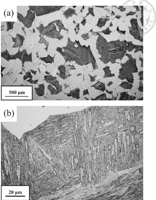
dilatometer. After austenization at 1200 ºC for 3 min, the specimens were rapidly cooled to 720 ºC holding for 7 min, and finally quenched to room temperature. ... 69 Figure 4-2 The prior austenite grain structure of Cu-Ti steel after direct quenching. The
specimen was austenitized at 1200 ºC for 3 minutes, followed by direct quenching to ambient temperature. (a) 100x and (b) Magnified image in 1000x. ... 70 Figure 4-3 Optical metallograph of dual phase microstructure of Cu-Ti steel. The
specimen was austenitized at 1200 ºC for 3 minutes, followed by cooling to
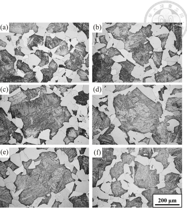
720 ºC for 7 minutes, then rapidly quenched to ambient temperature. (a) 100x and (b) Magnified image in 1000x ... 71 Figure 4-4 Optical metallography of dual phase microstructure in Cu-Ti after tempering
at 500 ºC for (a) 0.5h, (b) 1h, (c) 3h, (d) 5h, (e) 7h, and (f) 9h. ... 81 Figure 4-5 Magnified optical metallography of martensite microstructure. (a) step-
quench condition, (b) tempering at 500 ºC for 0.5h, and (c) tempering at 500 ºC for 9h. ... 82 Figure 4-6 Hardness evolution of ferrite and martensite in step-quenched Cu-Ti steel
tempering at 500 ºC for several time intervals. ... 83 Figure 4-7 To clarify the effect of holding temperature in two phase regions, after
austenization at 1200 ºC for 3 min, the specimens were rapidly cooled to 720 ºC and 650 ºC holding for 7 min and 250 seconds, respectively, then quenched to room temperature. ... 83 Figure 4-8 Optical metallograph of Low-T in Cu-Ti steel. The specimen was
austenitized at 1200 ºC for 3 minutes, followed by cooling to 650 ºC for 250 seconds, then rapidly quenched to ambient temperature. (a) 100x and (b) Magnified image in 1000x ... 84 Figure 4-9 Hardness evolution of ferrite and martensite in High-T and Low-T condition
of Cu-Ti steel tempering at 500 ºC for several time intervals. ... 85 Figure 4-10 Optical metallograph of dual phase microstructure in Cu steel. The
specimen was austenitized at 1200 ºC for 3 minutes, followed by cooling to 720 ºC for 7 minutes, then rapidly quenched to ambient temperature. (a) 100x and (b) Magnified image in 1000x ... 86
Figure 4-11 Microhardness evolution of tempering at 500 ºC for several time intervals (a) ferrite and martensite in Cu steel, (b) comparison of ferrite in Cu and Cu-Ti steel, and (c) comparison of martensite in Cu and Cu-Ti steel. ... 88 Figure 4-12 The step-quench process of Ti steel in order to clarify the effect of Cu
addition on tempering. After austenization at 1200 ºC for 3 min, the specimens were rapidly cooled to 650 ºC holding for 10 min, then
quenched to room temperature. ... 89 Figure 4-13 Optical metallograph of dual phase microstructure in Cu-free Ti steel. The
specimen was austenitized at 1200 ºC for 3 minutes, followed by cooling to 650 ºC for 10 minutes, then rapidly quenched to room temperature. (a) 100x and (b) Magnified image in 1000x ... 90 Figure 4-14 Microhardness evolution of tempering at 500 ºC for several time intervals
(a) ferrite and martensite in Ti steel, (b) Ti in comparison with Cu-Ti steel, and (c) Hardness difference between Ti and Cu-Ti steel (calculated by the value of Cu-Ti minus that of Cu). ... 92 Figure 4-15 TEM micrograph demonstrated highly dislocated lath martensite in as-
quench initial condition in Cu-Ti specimen... 101
Figure 4-16 TEM micrograph demonstrated the arrays of nano-precipitated carbides dispersed in the ferrite matrix in Cu-Ti steel, typical of interphase
precipitation in step quench condition with magnification of (a) 27k and (b) 67k, respectively. ... 102 Figure 4-17 TEM micrograph shown the highly dislocated lath martensite in step-
quench condition in Cu-Ti specimen after holding at 720 ºC for 7 min. .. 103
Figure 4-18 TEM micrograph shown microstructure in step-quench condition after holding at 720 ºC for 7 min in Ti-free Cu steel. (a) Random distributed Cu particles in ferrite matrix, (b) the highly dislocated lath martensite and (c) twin martensite ... 104 Figure 4-19 TEM morphology of Cu-Ti steel aging at 500 ºC for 3h. (a) interphase-
precipitated carbides in ferrite, (b) tempered martensite dispersed with 3 variants of cementite, (c) coalescence of lath martensite dispersed with copper precipitates and coarse cementites along the subgrain boundaries, and (d) magnification of (c). ... 106 Figure 4-20 TEM morphology of Cu steels aging at 500 ºC for 3h. (a) densely random
precipitation of copper in ferrite and (b) tempered martensite dispersed with copper precipitates and coarsened cementites located along the subgrain boundaries ... 107 Figure 4-21 Diffraction pattern in ferrite matrix in Cu steel after aging for 3h. The ring
pattern indicated that fcc Cu precipitates have random orientation
relationship with the matrix. ... 108 Figure 4-22 The selected-area diffraction pattern (SADP) of ferrite matrix with beam
direction parallel to [001] direction in ferrite. The (111) spot of fcc Cu precipitate exhibited an angle of 12º from (110) spot of bcc ferrite. .... 109
Figure 4-23 STEM image of step quench condition (holding at 720 ºC) with annular detector camera length of (a) 3.254m and (b) 222mm, resulting in inverse contrast. ... 110 Figure 4-24 The homogeneous distribution of dislocation within the ferrite grain with
interphase-precipitated carbides. ... 111 Figure 4-25 Change of sheet spacing of interphase-precipitated carbides in ferrite. .... 111 Figure 4-26 Change in morphology from planar interphase precipitation (PIP) to curved
interphase precipitation (CIP) in the ferrite matrix. ... 112 Figure 4-27 Energy dispersive x-ray spectrum (EDS) line scanning in the interphase of
ferrite and martensite ... 113 Figure 4-28 (a) Cu particle on the interphase-precipitated carbide in peak aging
condition of 4h and (b) magnified image of (a)... 114 Figure 4-29 (a) denser copper particle distributed on the sheet of interphase-precipitated
carbide in overaging condition of 8h and (b) magnified image of (a). ... 115 Figure 4-30 STEM-EDS mapping of interphase-precipitated carbides in the ferrite
matrix at (a) step quench condition and (b) aging at 500 ºC for 3h with corresponding Cu and Ti as well as overlapping signal in Cu-Ti steels. 116 Figure 4-31 Successive high resolution images of interphase-precipitated carbides in
peak aging condition (3h) of Cu-Ti steel. ... 117 Figure 4-32 (a) HRTEM image of nanometer-sized carbide in [010] zone axis of ferrite
matrix as well as (b) the corresponding fast Fourier transform diffractogram in step quench condition of Cu-Ti steel. ... 118 Figure 4-33 (a) HRTEM image of nanometer-sized carbide in [010] zone axis of ferrite
matrix as well as (b) the corresponding fast Fourier transform diffractogram in peak aging condition (aging for 3h) of Cu-Ti steel. ... 119 Figure 4-34 (a) High resolution image of 9R particles in the ferrite matrix in the peak
aging condition in Cu-Ti steel and (b) the corresponding fast Fourier transform diffractogram showing (c) the twinning relation of two variants.
... 120 Figure 4-35 Schematic diagram showing the isothermal treatment performed in the
Gleeble simulator. After austenization at 1050 ºC for 30sec, the specimens were cooled to 650 ºC holding for 20sec, and finally quenched to room temperature. ... 126 Figure 4-36 Optical metallograph of dual phase microstructure of Gleeble specimen in
Cu-Ti steel. (a) 200x and (b) Magnified image in 1000x. ... 127 Figure 4-37 Engineering stress-strain curve of step-quench condition (labeled as
Quench), aging for 3h and aging 5h in Cu-Ti steels. ... 128 Figure 4-38 (a) True stress-strain curve and (b) strain hardening rate curve of step-
quench condition, aging for 3h and aging 5h in Cu-Ti steels. ... 129 Figure 4-39 SEM images showing the deformation structure of dual-phase steel in (a)
step-quench condition, (c) aging for 3h and (e) aging for 5h. ... 132 Figure 4-40 Illustration of simulated coiling process of dual-phase steels in Cu-Ti
specimens. The specimens were austenitized at 1200 ºC for 3 minutes, followed by cooling at the rate of 20 ºC/s to 720 ºC for 7 minutes, then cooled to different coiling temperature (350 ºC, 400 ºC and 500 ºC) for several hours (1h, 2h, 4h, 8h, 12, 24h and 36h) and then cooled to room temperature. ... 138 Figure 4-41 Hardness evolution during the simulation coiling process with temperature
of (a) 500 ºC (b) 400 ºC and (c) 350 ºC for several hours. ... 139
Table Content
Table 3-1 Chemical composition of the steels studied (in wt%) ... 61 Table 4-1 Comparison between High-T specimen (holding at 720 ºC) and Low-T
specimen (holding at 650 ºC). ... 85 Table 4-2 Comparison between Cu-Ti and Cu specimens in step-quench condition
(holding at 720 ºC). ... 87 Table 4-3 Comparison between Cu-Ti and Ti specimens in step-quench condition
(holding at 650 ºC). ... 91 Table 4-4 Mechanical properties of step-quench, aging for 3h, and aging for 5h. . 126
Chapter 1 General Introduction
For the sake of reducing the CO2 emission and improving for the efficiency of fuel consumption in the next generation of vehicles, light-weight design with usage of advanced high-strength steels (AHSS) for durability and safety play an important role in automotive industries in recent years. Several types of advanced high-strength steels (AHSS) have been developed, including dual-phase (DP) steel, complex phase (CP) steels, transformation-induced-plasticity (TRIP) steels, twinning-induced-plasticity (TWIP) steel and quench-partitioning (QP) steels. In 1960s, dual-phase steel aroused lots of interests by its distinct mechanical properties, including continuous stress-strain curve without upper and lower yield points, high work hardening rate and low yield strength to ultimate tensile strength ratio (YS/UTS), which lead to combination of good strength and formability. Nowadays, DP steels have been widely implemented in automotive industries owing to relatively low production cost and superior mechanical properties. According to Ultra-Light Steel Auto Body-Advanced Vehicle Concepts (ULSAB-AVC) Program, aiming at the most environmentally optimal and affordable material for future generations of vehicles, DP steels make up about 75% of high strength sheet material used in car bodies[1].
In addition to DP steels, with increasing environmental consideration, copper- bearing steel has called lots of attentions as a part of residual elements contained in
recycling steel scraps for producing considerable amounts of commercial steels.
Therefore, the development of Cu bearing high-strength dual-phase steels with better mechanical properties is very attractive from both the economic and environmental points of view.
In addition, nano-sized precipitation hardening effect is known to be one of most effective strengthening mechanisms in steels[2]. Especially, vanadium, titanium, molybdenum and niobium carbides have been studied for their precipitation hardening effect. However, copper does not form intermetallic compounds such as carbide or nitride in steels. On the contrary, copper-bearing steels are strengthened by copper precipitation hardening. Most literatures focus on the aging behavior of copper
precipitation hardening, including quench and tempering (QT) process of martensite[3- 13], bainite[14, 15], ferrite[16] and austenite[17] and the temporal evolution of Cu precipitation has been widely investigated to elucidate the effect of precipitation
hardening [15, 16, 18-23]. The initial stage of Cu precipitate is bcc Cu-rich clusters that are coherent with matrix, and the bcc clusters transform to 9R Cu with or without twins after exceeding a critical size. Further transformation of 9R to twinned fcc Cu occurs by the glide of ±𝑎/3[100]9𝑅 dislocations. Finally, twinned fcc Cu transformed into equilibrium perfect fcc structure by elimination of twining structure.
The objective of the present work is to clarify the effect of dual precipitation of
interphase-precipitated carbides and nanometer-sized copper particles in a low carbon Cu-Ti-bearing dual-phase steel from a step-quench process and to investigate hardness evolution with the effect of aging treatment at elevated temperature. In Chapter 2, fundamental background of DP steels as well as the brief introduction of AHSS is established. In addition, the basic knowledge about the effects of copper addition and temporal evolution of Cu precipitation as well as interphase precipitation of alloyed carbides is reviewed. In Chapter 3, the experimental procedures and characterization techniques are discussed. And the detailed experimental results about the aging behavior of copper-bearing dual-phase steels and extensive discussion are presented in Chapter 4.
Chapter 5 provides general conclusions and summaries concerning the findings from the
research.
The present research “TEM Investigation on the Dual Precipitation Behavior of Nanometer-sized Carbides and Copper Precipitates in High Strength Copper-Bearing Dual-Phase Steels” attempts to design a new material with superior mechanical properties with great interest both for industrial application and scientific research.
Chapter 2 Literature Review
2.1 Introduction of Dual-Phase Steels
In the mid 1960’s, dual-phase (DP) steels were first developed at BISRA (British Iron and Steel Research Association) in the United Kingdom as well as Inland Steel Corporation in the United States. Dual phase steels are defined as a class of steels with microstructure composed of ferrite and martensite, as illustrated in Figure 2-1. Typical dual-phase steels, consisting of about 75-85 volume percent soft ferrite matrix, with remainder of mixture of martensite, bainite, and retained austenite[24], exhibit a superior balance between formability and strength than plain carbon steels or high- strength low-alloy (HSLA) steels of similar tensile strength[24] (Figure 2-2). To achieve the increasing demands in the automotive industry for designing light-weight high strength steel sheets, dual phase steels have been remarkably studied by different alloy design and heat treatment to tailor the microstructure. According to Ultra Light Steel Auto Body-Advanced Vehicle Concepts (ULSAB-AVC) Program, aiming at the most environmentally optimal and affordable material for future generations of vehicles, DP steels make up about 75% of high strength sheet material used in car bodies (Figure 2- 3)[1]. In this section, fundamental background of dual-phase steel is established as well as the brief introduction of advanced high strength steel.
2.1.1 Brief History of Dual-Phase Steel
In the past century, the demand for steels and the requirements for specific
applications has dramatically increased. Even though countless new materials come into the world, steels still play important roles in structural as well as functional materials in our daily lives. After oil crisis bursting out, the reconsideration of steel design for reduction of fuel consumption has been put in the first place for many material designers and engineers. As a result, methods to strength enhancement of steels are required to light-weight design of automobiles with thinner steel plates. High-strength low-alloy (HSLA) steels which come from plain carbon steels and mild steels
represented a new category of materials. Their chemical composition contains less than 1 weight present of other alloyed elements such as Mn and Si and typical mechanical properties of yield strength and tensile strength range from 150 to 200 and 280 to 350 MPa, respectively, and total elongation of 30-40%[25]. Although HSLA steels have an excellent balance of mechanical properties, their formability or ductility was not enough for the manufacture of automotive applications. DP steels which evolved from HSLA steels and combined strength with ductility started to attract great attentions of metallurgists and engineers in 1970’s[24]. Microstructure of dual-phase steels
comprised of ferrite and martensite provides potentials for better formability than HSLA steels with similar tensile strength. About a decade later, in several countries such as
Japan and United states confirmed the target of tensile strength of 500-600 MPa at elongation of 20-30% for dual-phase steels. However, despite the fact that the treatments of continuous annealing and galvanizing lines are effective for producing dual-phase steels, some drawbacks, for its higher requirement of wear resistance of tooling, unpredictable spring-back and some welding problems, limit the possibilities of commercial production. Faced with these obstacles of production in automobile
industries, dual phase steels seemed to come to an end in the 1980s. Thanks to the gradually rising awareness of safety in automobiles, carmakers sought for higher critical strength for safety requirement, and dual-phase steels resurged in that moment and started to escalation. In the middle of 1990s, advanced high strength steels (AHSS) such as DP 590 for cold forming successfully commercialized in the USA and as well as other growing application and commercial supply in high strength DP steels all over the world. To reach the requirements of safety of transportation, economic savings and environmental friendliness, the competition between light-alloys such Al, Mg and Ti and advanced steels results in the rapid development of steels with higher strength and good formability.
2.1.2 Advanced High Strength Steels
Advanced high strength steels (AHSS) are evolved from HSLA steels for further reaching the demand of combination of high strength and formability in the complex design with safety requirement in automobile industries. The terms “advanced high strength” implies that the yield strength is above 300 MPa and the tensile strength is above 600 MPa respectively for part thickness reduction and improved formability.
While dual-phase steels occupy a main part in AHSS, several categories such as TRIP steels, complex phase steels, TWIP steels, Q&P (quenching and partitioning) steels and other advanced steels have developed rapidly in recent years. TRIP steels with
Transformation-Induced Plasticity due to strain-induced martensitic transformation exhibit extremely high strain hardening rate and uniform elongation due to retardation of local necking that can help ensuring extremely high energy absorption at
collisions[26]. TRIP steels demonstrated good stretchability, higher absorbed energy and fatigue limit compared to conventional DP steels with the same yield strength[27].
To achieve a specific formability, that is, flangeability, or ability to hole expansion, a homogeneous microstructure with slight difference in strength between microstructure constituents is essential to achieve a high hole-expanding ratio. As a result, complex phase (CP) steels with ferrite–bainite (or with some martensite) microstructure with dominant bainitic matrix, and advanced DP steels modified by strengthening ferrite
phase by addition of Si or by precipitation hardening to decrease the strength difference between phases aim to promote the flangeability.
At the beginning of 21th centaury, high Mn TWIP (Twinning Induced Plasticity) austenitic steels were developed with combination of about 1 GPa tensile strength and 50-60% total elongation. Nowadays, baking hardenability is an important characteristic in AHSS, and that represents ability to enhance the YS (about 40MPa) after forming.
Specifically, DP, TRIP and TWIP steels exhibit high potential for energy absorption are used for parts that are able to withstand dynamic loading during collisions in cars. On the other hand, modified DP steels, as well as martensitic steels with high yield-to-tensile strengths ratio, are used for applications in high loading situations, which require high stiffness, high safety factor in automobiles. These steels with dramatically improved mechanical properties are regarded as second generation of AHSS.
2.1.3 Heat Treatment and Effect of Alloying Element
Alloy design and heat treatment process are the most common ways to tailor the microstructure of steels including DP steels. To obtain dual-phase microstructure with well-dispersed martensite in polygonal ferrite, several heat treatments are typically applied. Two primary processes are intercritical annealing and step quenching. The former process includes reheating of initial cold-rolled ferrite-pearlite or ferrite-bainite microstructure into the range of two phase region (between Ac1 and Ac3), followed by quenching below the martensite start temperature (Figure 2-4 (a)). The latter process is first heating to austenization temperature, then cooling to two phase region, followed by quenching below the martensite start temperature (Figure 2-4 (b)). The advantage of intercritical annealing is that the morphology of dual-phase microstructure can be controlled by the initial microstructure. When a preliminary-quenched steel with martensite microstructure is heated into the intercritical region, austenite first nucleates at the prior austenite grain boundary triple junctions, then at the surfaces of prior austenite grains, and finally at martensite plate/lath boundaries. This produces a Widmannstatten-like microstructure with acicular shape of austenite that may have transformed to martensite upon cooling retaining fibrous morphology[28-30]. While in the case of ferrite and pearlite structure, due to the preferential nucleation on the ferrite/pearlite interface, the final morphology after intercritical annealing will be fine
globular martensite islands distributed along the ferrite boundaries[31]. Although intercritical annealing provides an effective way to tailor the morphology of dual-phase steels, it needs to consume more energy for twice heating and cooling process, however.
In step quenching process, two-step controlled cooling process seems more feasible in industrial application when facing with severe energy-conserved requirement nowadays.
For long, accurate control of temperature had been primary challenge of step quenching process due to the short time period of holding time and temperature-sensitive
microstructure. Delicate instruments developed nowadays provide effective way to overcome it. In addition, in practice, intercritical annealing heat treatment is for cold rolling steel strip while step quenching is for hot rolling process.
Other than heat treatment, alloy elements also play an important in DP steels. The main alloy elements in DP steels are carbon, silicon and manganese due to their ability to retard pearlite and bainite transformation[32], allowing for a wider range of cooling rate. For achieving the desired microstructures, DP steels typically contain 0.06–0.15%
C (weight percent) and 1.5–3% Mn; the former strengthens the martensite, the latter causes solid-solution strengthening in ferrite, and both are austenite stabilizers. Carbon addition has noticeable effect on increasing hardenability but at the expense of
toughness and weldability. As a result, manganese is usually added to compensate for hardenability in low carbon steels. Silicon is able to increase the hardenability and make
it easier to obtain martensite, but more importantly, Si reduces the carbon content of ferrite, which will lead to a cleaner, more ductile ferrite. However, silicon is a ferrite stabilizer and exclusive to carbon atoms, so it lowers the carbon solubility in the ferrite.
Silicon addition is able to promote ferrite transformation and expand ferrite-austenite two-phase region, making it more accessible to control the volume fraction of DP steel during heat treatment. Furthermore, Cr and Mo, as ferrite-inhibitors, also can be used to retard pearlite or bainite reaction, and several strong carbide forming element, Ti, V and Nb, are often used for precipitation strengthening and grain refinement.
By properly designing the heat treatment processes and alloy elements, specific microstructure and mechanical properties of dual-phase steels can be successfully achieved.
2.1.4 Mechanical Properties of Dual-Phase Steels
The mechanical behavior of dual-phase steels depends on the properties of the constituent phases. As a result of hard martensite islands located in the soft ferrite matrix, dual-phase steels demonstrated some special mechanical properties, such as great combinations of tensile strength and elongation, high strain and bake hardening, as well as higher fatigue resistance. Other distinctive features of dual phase steels are continuous stress-strain curve with no yield point elongation, high initial strain
to-TS ratio (Figure 2-5). Each of these features in stress-strain curve can be correlated with the deformation responses of microconstituents. The low yield strength and absence of yield point elongation are attributed to the presence of numerous unpinned and mobile dislocations in the ferrite near to ferrite/martensite interphase generated by stresses imposed by volume change when austenite transforms to martensite[33-35]. As shown in the Figure 2-6, the geometrical necessary dislocations (GNDs) near
ferrite/martensite phase boundary can be seen under TEM observation. Geometrical necessary dislocations form at temperature lower than Ms, so their mobility is relatively high and solute-dislocation interactions are heavily reduced. As a result, much lower stresses are required for initial plastic deformation. At the same time, no initial threshold stress is needed to break the dislocation away from solute atoms, so the yield point is absent.
The advantage of low YS-to-TS ratio in the conventional dual phase steels (about 0.5) is for safety concern. High resistance to deformation from yielding to plastic instability, which can prevent the sudden decrease in the strength and provide superior strain capacity [36]. However, high yield strength are also required in DP steels for some specific engineering application, for example, pipelines for natural gas [37].
Pipelines over land or under water may experience severe strains and stress to traverse a long distance. In addition, the large difference in the strength between the two phases
might have a deleterious effect on toughness since cracks can easily nucleate at the hard second phase particles at low temperatures. As a result, it is important to obtain both high yield strength with enough YS-to-TS ratio. In advanced DP steels, nano-sized carbide dispersion, which is considerably involved with precipitation hardening, is consequently introduced to DP steels to enhance yield strength with YS-to-TS ratio about 0.9. In addition, Si addition is also an effective method to increase the yield strength by substitutional solid solution strengthening [38] and promoting carbide precipitation [39].
Another feature of DP steels is high initial strain hardening rate, which is
decreasing with strain until reaching some strain points. This phenomenon is associated with the TRIP effects from retained austenite and high density of GNDs. From analysis on strain hardening rate, DP steels are reported to undergo multi-stages deformation due to the absences of single strain hardening exponent value[34]. Korzekwa et al. proposed that dual-phase steels often show three well-defined stages of strain hardening, as illustrated in Figure 2-7. In his study, the multi-stages strain hardening behaviors were related to dislocations substructure evolution and distribution. The initial stage with high strain hardening rate was believed to be associated with the interactions of the quenched-in dislocations (GNDs) and residual stresses with the applied stresses at very low plastic strains. With increasing strain, the formation of new dislocations inside the
ferrite grain and constraints to dislocation movement from martensite and dislocation cell results in moderate decrease in strain hardening rate. In the last stage of
deformation, the dislocation substructure, because of dynamic recovery and the
relatively small changes with strain in the dimensions of the dislocation cells, is not able to significantly raise flow stress with increasing strain, and the rate of strain hardening decreases further. Dual-phase with complicated substructures and the large variations in dislocation density exhibits multi-stages work hardening mechanism.
2.1.5 Inhomogeneous Deformation Behaviors of Dual Phase Steels
The deformation behavior of dual-phase steels depends on the properties of the constituent phases and their volume fractions [40, 41] as well as morphology [31, 42- 45]. The strength of the ferrite phase is mainly controlled by the steel composition, grain size, and initial dislocation density, which is primarily affected by geometrical necessary dislocations[46]. The strength of martensite depends primarily on its carbon content and its morphology. Due to the difference in strength between the two phases, the
distribution of stress and strain between ferrite matrix and martensite is inhomogeneous[47, 48].
During the initial stage of deformation, as a result of the identical elastic moduli of ferrite and martensite, there is no load transfer and the two phases deform
simultaneously in elastic region. After reaching the yield point of ferrite, which is also yield point of DP steel, the stress is transferred into the non-deformed martensite islands[49]. During the transitional strain, martensite islands are subjected to much higher stress but lower strain than ferrite. Less strain in martensite and a higher strain in the ferrite during deformation of the DP steels lead to delayed necking and retarded strain to fracture[45, 50]. The onset of plastic flow and work hardening of martensite commence after the stress exceeds its yielding stress, but well before ultimate tensile strength is reached in the dual-phase steel[51]. Martensite with higher strength will deform later because the partitioning stress in martensite is lower than its yield stress in later region of deformation[52]. Factors such as carbon content, volume fraction and morphology of martensite as well as strength ratio of the two phases determine the initiation of martensite deformation.
Briefly, strain and stress partitioning dominate the deformation behavior of dual phase steels, which can be separated into three stages: prior to yielding of ferrite, between yielding points of ferrite and martensite and after yielding of martensite. In the first and last stage, two phases co-deform in elastic and plastic manners, respectively.
While in the second part, the deformation is inhomogeneous, containing hardening of ferrite and stress transfer into non-deformed martensite.
2.1.6 Improvement in Formability of Dual Phase Steels
Owing to ferrite-martensite microstructure, DP steels exhibit better formability than conventional HSLA steel of the same strength level. The characteristic of DP steel is a relatively low yield strength and high initial work hardening resulting in a high n- value. The high n-value renders DP steels good protection against local thinning under the forming processes of drawing and stretching. However, practical experience has shown unexpected failure in forming operations where tight bending, stretch flanging or hole expansion are predominant. The inhomogeneous microstructure of soft ferrite and hard martensite in combination with local straining is inherent to these problems.
Highly localized strain and severe dislocation pile-up are occurring in individual ferrite grains leading to delamination at the ferrite-martensite phase boundary or to cracking of martensite islands as demonstrated in Figure 2-8[53]. As result, DP steels exhibit a relatively poor bendability and hole expansion ratio despite great draw and stretch formability. A low hole expansion ratio is a common disadvantage of all multi-phase steels containing hard and soft phases (Figure 2-9). As a result, it is essential to improve hole expansion ratio and bendability in DP steel for some specific manufacturing
process.
Forming problems can be alleviated by microstructural refinement and
homogenization of the phases as well as reduction of hardness contrasts of both phases.
Microstructural refinement and narrower gap of hardness between the ferrite and martensite mitigate the inhomogeneity strain distribution and raise the hole expansion ratio. As a result, martensite can be softened by carbon content control or tempering and ferrite can be strengthened by solid solution strengthening, grain refinement as well as precipitation hardening. Mohrbacher reported that, niobium and molybdenum are key alloying elements to improve the hole expansion ratio [53]. In addition, Fang et al.
found out that yield to tensile strength ratio is linearly related to hole expansion ratio[54] and the hole expansion property increases significantly at the tempering temperature ranging from 200 to 300 ºC[55]. Generally speaking, modified alloy
concepts in combination with adapted processing have been identified as an appropriate approach to achieve the requiring mechanical properties.
2.1.7 Effect of Tempering on Dual Phase Steels
The response to temperature of dual phase steels has drawn considerable attention [56-62]. The influence of tempering on the properties of DP steels is becoming
important due to the current trends to utilize higher tempering temperatures (up to 450–
500 ºC) to improve the behavior of AHSS during localized deformation such as cut edge and hole expansion. Although most of dual phase steels are intended for use without any tempering treatment, the reheating, or tempering/auto-tempering process is often an incidental step either during annealing or slow cooling, when production or in the final process of stamped parts during baking of protective paint coating[56]. Multiphase steels including dual-phase steels show a strong bake hardening effect being of importance for shaping of car body structural parts[57].
The strength of both ferrite and martensite decreases during reheating process. The major distinctions of tempering DP steels stem from super-saturation of ferrite with interstitial atoms, residual stresses in ferrite[58], higher localized dislocation density in ferrite grains near the boundaries with martensite, fine sizes of retained austenite grains[59], and from inhomogeneous volume distribution of carbide precipitates. The most important “internal” parameters that influence the tempering effects in dual-phase steels are the annealing temperature and the rate of cooling from the intercritical region, i.e., the factors that control the concentrations of interstitials in ferrite, the volume
fraction of martensite and its carbon content, as well as the amount of retained austenite.
When DP steel contains low-carbon martensite, it can be auto-tempered during slow cooling due to high Ms temperature (usually above 300 ºC). During low-temperature tempering at 200 ºC, DP steels demonstrate diffusion of carbon atoms in ferrite towards dislocations and relaxation of residual stresses as well as precipitation of carbides along the martensite lath or packet boundaries [59]. Additional dislocations generated during cold deformation of DP steels enhance the driving force of the interstitial atoms to diffuse towards dislocations promoting the precipitation of ultrafine carbides in ferrite during heating, in particular at 170–200 ºC for baking paint, thus producing a marked strengthening by strain aging termed bake hardening[60]. The dislocation density in ferrite in the vicinity of ferrite–martensite boundaries substantially decreases during tempering. However, carbides that precipitate at dislocations delay the recovery effect with the annihilation of dislocations[63], and therefore higher strength of ferrite in a dual-phase steel can be preserved during tempering.
Tempering has been used successfully to improve the strength to elongation ratio of dual phase steels after intercritical annealing. Fonstein et al. [62]has studied the typical changes in mechanical properties upon tempering (Figure 2-10). The
discontinuous yielding and upper–lower yield points return as increasing carbon content in ferrite when the temperature approaches Ac1 and the related acceleration of free
dislocations pinning. In addition, ultimate tensile strength decreases at higher tempering temperatures. Improvement of ductility of dual-phase steels after tempering at
temperatures above 300 ºC is believed to be primarily by larger post-uniform deformation[61] as a result of better strain compatibility between the phases and the suppression of microvoid nucleation and growth. The increased ductility along with lower strain hardening and smaller differences in hardness of ferrite and martensite with increase in temperature of tempering result in substantial improvement of stretch
flangeability evaluated by hole expansion.
In this study, interphase-precipitated titanium carbide and copper particles are introduced to strengthen the ferrite phase in an advanced DP steel and the tempering effects are also examined.
Figure 2-1 The typical microstructure of dual-phase steels. The grain of bright contrast is the polygonal ferrite phase and the grain of dark contrast is the martensite phase.
Figure 2-2 Strength-ductility relationship of dual phase steels compared with that for plain carbon and HSLA steels. The dual phase steel curve is far above that for ferrite- pearlite steels[24].
Figure 2-3 PNGV-Class body structure steel/grade distribution of ULSAB-AVC[1].
Figure 2-4 Schematic representation of heat treatments of dual phase steel[24].
(a) Intercritical annealing (b) Step quenching
Figure 2-5 (a) Schematic stress-strain curve. (b) strain hardening rate-strain curve for dual phase steels (GM980X), HSLA (SAE950X and SAE980X) and plain carbon steel[24]. Relative low yield strength to ultimate tensile strength ratio and continuous yielding of dual phase steel are shown in (a) and high initial strain hardening rate of dual phase steel is presented in (b).
Figure 2-6 Bright field transmission electron microscopic image of the dual-phase steel showing two ferritic grains (F) separated by martensitic regions (M). The dislocation density near the ferrite/martensite phase boundary is higher than in the interior of the grains[35].
Figure 2-7 Jaoul-Crussard plot for the C-Mn-Si dual-phase steel showing points at which dislocation structures were studied[34].
Figure 2-8 Features and mechanisms of damage initiation and propagation in DP steel[53].
Figure 2-9 Influence of microstructures on the hole expansion ratio[53].
Figure 2-10 Effect of tempering temperature on strength characteristics (YS, TS, and YS/TS ratio) of 0.08C–2.1Mn–0.7Si–Mo DP steel [62].
2.2 Introduction of Copper Bearing Steels
Nowadays, copper-bearing steels are widely used in industrial applications, especially in severe weather corrosion condition, such as construction sectors, offshore infrastructure, power plant structures, railways and vehicle body parts.
In the past three decades, there has been a dramatic proliferation of research on copper-bearing high-strength low-alloyed (HSLA) steels, particularly in pressure vessel steels which are used for nuclear reactors[4, 64]. Low carbon steels containing 1-2%
copper have been attracted lots of attention from thin sheets to thick plates owing to their good combination of strength, toughness and weldability[16], making them suitable for severe applications in natural gas pipelines, offshore platforms and nuclear reactors[65]. Moreover, with increasing environmental consideration, copper has carried much weight due to as a part of residual elements contained in recycling steel scraps that considerable amounts of commercial steels that are produced from[66].
In this section, emphasis is put upon the basic knowledge about the effects of copper addition and temporal evolution of Cu precipitation as well as the strengthening effect.
2.2.1 Effects of Copper Addition in Alloyed Steels
Extensive researches have investigated the effect of copper addition on the advanced steel applications, especially as steels plates for offshore structures. The addition of copper to structural steels for its ability to impart good weathering properties, begin in early 20th in the United States[67].
In the early 1970s, high-yield steels (HY-100 and HY-80) which were designed for the US naval submarine hull and aircraft carrier demonstrated good strength but low weldability[68]. To Achieve the demand for good combination of strength, toughness and weldability, several low-carbon, copper precipitation strengthened HSLA steels (HSLA-100 and HSLA-80) emerged in the 1980s[69, 70].
Cu alloyed in low concentrations (0.15-0.25 percent) in steels are widely known for improving atmospheric corrosion resistance [71, 72]. Other than corrosion resistance application, copper-bearing steels exhibit precipitation of Cu making great contribution to the mechanical properties. Gregg and Daniloff [73]reported that the solubility of copper in α-iron is 0.4 wt.% at temperature below 600 ºC as in the iron-copper phase diagram (Figure 2-11). Because copper-bearing steels usually contain more than the solubility limit of copper, it is advantageous for copper to precipitate. Copper atoms are sized by 0.2556 nm in diameter, showing only 3% difference compared with Fe atoms (0.2548 nm), and they are either dissolved in α-Fe as substitutional atoms or precipitated
as ε-Cu particles without forming intermetallic compounds in steels[74]. In HSLA-100, copper act as a crucial role to compensate for the strength loss due to low carbon alloy design, which reduce the fabrication cost and improve the toughness as well as
weldability. In addition, for the sake of enhancing hardenability of austenite, several alloying elements, such as Ni, Mn, Cr and Mo, are added in Cu-bearing steels. Ni is also added to prevent the so-called hot shortness and irradiation embrittlement and both Ni and Mn can promote the nucleating rate of Cu[75, 76]. V, Ti and Nb, known as strong carbide forming elements, are utilized for grain refinement of austenite.
Furthermore, aging behavior of copper precipitation hardening has been
thoroughly studied, including quench and tempering (QT) process of martensite[3-13], bainite[14, 15], ferrite[16] and austenite[17]. Tempering treatment induces the
formation of fine particles of copper which are able to retard the annealing of the bainitic or martensitic matrix thereby retaining high strength without jeopardizing toughness[3-12, 73, 77]. Therefore, copper-bearing bainitic/martensitic steels are widely used for applications in heavy engineering, especially for low temperature application.
In sour service line pipe application, copper can act as an effective element to replace Mn, which forms elongated MnS that leads to hydrogen induced blister cracking, with increasing both strength and low temperature toughness[78].
Moreover, copper, as an austenite stabilizer, is found beneficial to promote higher
retained austenite and therefore higher ductility of TRIP effect[79]. Dieudonne et al.[80, 81] and Toyoda et al.[82, 83] also study the effect of Cu on improving resistance to hydrogen embrittlement, corrosion behavior delayed fracture in TWIP steels. However, excess Cu addition may form liquid phase at grain boundaries and cause hot shortness during hot working[84], as previously mentioned. It is clarified that the addition of Ni can increase the solubility of Cu as well as melting point of Cu-rich phase, and therefore suppress the surface hot shortness[85, 86]. In summary, Cu can be utilized as a
beneficial tramp element to design an excellent eco-material with superior mechanical properties along with good recyclability.
2.2.2 Temporal Evolution of Copper Precipitation
The aging behavior of precipitates in low-carbon copper-bearing steels has raised lots of interest due to the contribution to excellent strength/ductility balance. As a result, extensive research on temporal evolution of Cu precipitation has been widely
investigated to elucidate the effect of precipitation hardening [15, 16, 18-23]. Thompson et al.[87, 88] has reported the copper precipitation at austenite/ferrite interface and within ferrite matrix during continuous cooling of commercial low alloyed steels (HSLA-100). In addition, Duune [89] found the peak hardness of cold rolled HSLA-80 with fine ε-Cu precipitates on dislocations in matrix, while DeArdo [90] reported that
coherent Cu clusters are contributed to peak aging strength of HSLA-100. Goodman et al. [91] proved that the initial Cu precipitates are not of a chemical composition of pure Cu, but Fe-rich Cu clusters by using field ion microscopy (FIM) and atom probe analysis. Buswell et al. [92] investigated a few nanometer-sized Cu precipitates as copper bcc clusters under two-beam conditions in peak hardness. In addition,
Maruyama et al.[16] have found that bcc and 9R structure exist prior to the formation of stable fcc Cu phase in low alloy ferritic and martensitic steel and in maximum age hardening condition, the structure of Cu particle is bcc. Furthermore, Miglin concluded that coherent bcc Cu clusters in HSLA steels are not visible due to not enough strain field contrast under the observation of transmission electron microscope[93]. With Cs- corrected high-angle annular dark-field (HAADF) scanning transmission electron microscopy imaging (STEM), Heo et al. [22] identified bcc Cu cluster in ferrite matrix (Figure 2-12). Bcc Cu clusters are thought to be not visible due to the absence of phase contrast in conventional high-resolution TEM, while by using this subatomic-sized electron beam and a HAADF detector with Cs-corrector, each atomic column in crystals can be revealed without any interference from strain field or moiré fringe contrast.
It has been proven that Cu precipitates begin with iron-rich bcc Cu cluster in bcc ferrite matrix[4, 91, 94-97], and lose coherency after reaching certain critical size[4, 91, 98, 99]. Then the bcc Cu clusters undergo a martensitic transformation into
orthorhombic twinned 9R structure after reaching critical size of approximately 2 to 4 nm[16, 21, 22, 94, 100, 101]. Othen et al. [100] identified the 9R structure,
characterized by a close-packed structure with stacking faults every third close-packed plane with the stacking sequence is ABC/BCA/CAB and herring-bone structure by (114̅)9R twins, which help to minimize the misfit with the iron matrix [100, 101], as illustrated in Figure 2-13. Nevertheless, in the research of Heo et al.,[22] 9R Cu
precipitates which have perfect 9R structure without any defects (twins or SF) were also observed (Figure 2-14). Formation of a 9R structure from a bcc crystal was explained by a displacive mechanism with repeated shear on {110}𝑏𝑐𝑐 planes in 〈1̅10〉𝑏𝑐𝑐 direction [21]. The diffraction pattern of 9R is identified in Figure 2-15 and the
orientation relationship between the 9R precipitates and ferrite matrix is as follows[100, 101]:
(114̅)9𝑅//(110)𝑓𝑒𝑟𝑟𝑖𝑡𝑒 [11̅0]9𝑅//[11̅1]𝑓𝑒𝑟𝑟𝑖𝑡𝑒
With the movement of a ±𝑎/3[100]9𝑅 Shockley-type partial dislocations, 9R Cu will transformation into a twinned fcc structure (Figure 2-16). With further progress of aging, twins in a fcc Cu precipitate tend to disappear, resulting in thermodynamically stable fcc structure, typical termed as ε-copper, due to lattice relaxation[18, 21, 22]. The equilibrium ε-copper adopts the Kurdjumov-Sachs (KS) orientation relationship[77, 88, 102] with ferrite matrix, i.e.
(111)ε−copper//(110)𝑓𝑒𝑟𝑟𝑖𝑡𝑒 [110]ε−copper//[111]𝑓𝑒𝑟𝑟𝑖𝑡𝑒
In summary, the temporal evolution of nano-sized copper precipitation can be identified, as illustrated in Figure 2-17. The initial stage is bcc Cu-rich clusters that are coherent with matrix. With further aging, precipitates of 9R Cu with or without
(114̅)9𝑅 twins are formed from bcc Cu. Further transformation of 9R to twinned fcc Cu occurs by the glide of ±𝑎/3[100]9𝑅 dislocations. Finally, twinned fcc Cu transformed into equilibrium perfect fcc structure by elimination of twins thermodynamically.
2.2.3 Strengthening Mechanism of Copper Precipitation
Precipitation strengthening in copper-bearing steels have been widely debated for several decades. Due to the complicated sequence of precipitation, the contribution of the precipitates to the strength of the steels is hard to present in a simple model.
DeArdo has concluded that coherent bcc Cu clusters are contributed to peak aging strength mainly in HSLA-100[90]. Russell and Brown[103] have generally attributed strengthening mechanism of copper-rich bcc clusters to a difference in modulus between the precipitate and iron base solid solution matrix. Osamura et al. [104] assume that hardening effect in the initial stage is controlled by coherency strains of bcc cluster by using small-angle neutron scattering (SANS).
In the study of Fine and Isheim[19], the origin of strengthening mechanism of bcc
Cu clusters has been predicted by ab initio computed elastic constants. The misfit strengthening, chemical strengthening and modulus difference strengthening are
predicted to be small, however. Moreover, Harry and Bacon[105, 106] used many body potentials to simulate 〈111〉 screw dislocations in bcc Cu precipitates by molecular dynamics and suggest that the dislocation core–precipitate interaction is the major source of the precipitation strengthening. Harry and Bacon also suggest that a dislocation moving through a bcc Cu precipitate with an energy-lowering
transformation from the bcc structure to one locally-resembling fcc structure, that is, 9R structure[106].
Deschamps et al.[65] has analyzed the strength of individual precipitates increases with precipitate size based on the mechanical test results. Study of the plastic behavior shows that the maximum initial hardening rate is related to the highest strength of the material, as in Figure 2-18. The relatively high work hardening rate of the alloy at the peak strength may be associated with a stress or strain assisted transformation of the precipitates from the BCC to the 9R crystal structure.
Figure 2-11 Phase diagram of iron-copper system[73].
![Figure 2-3 PNGV-Class body structure steel/grade distribution of ULSAB-AVC[1].](https://thumb-ap.123doks.com/thumbv2/9libinfo/9599459.628662/44.892.135.782.124.490/figure-pngv-class-structure-steel-grade-distribution-ulsab.webp)
![Figure 2-7 Jaoul-Crussard plot for the C-Mn-Si dual-phase steel showing points at which dislocation structures were studied[34]](https://thumb-ap.123doks.com/thumbv2/9libinfo/9599459.628662/46.892.284.608.646.1065/figure-jaoul-crussard-showing-points-dislocation-structures-studied.webp)
![Figure 2-8 Features and mechanisms of damage initiation and propagation in DP steel[53]](https://thumb-ap.123doks.com/thumbv2/9libinfo/9599459.628662/47.892.245.785.117.388/figure-features-mechanisms-damage-initiation-propagation-dp-steel.webp)
![Figure 2-19 TEM image of interphase-precipitated carbides arranged in parallel sheets in the ferrite matrix (Fe-0.15C-0.75V)[107-109]](https://thumb-ap.123doks.com/thumbv2/9libinfo/9599459.628662/74.892.273.644.130.471/figure-interphase-precipitated-carbides-arranged-parallel-sheets-ferrite.webp)
![Figure 2-21 TEM image of three types of interphase precipitation[115]. (a) irregular CIP carbides, (b) regular CIP carbides, (c) a mixture of PIP and regular CIP carbides, and (d) PIP carbides](https://thumb-ap.123doks.com/thumbv2/9libinfo/9599459.628662/75.892.211.784.114.611/figure-interphase-precipitation-irregular-carbides-carbides-carbides-carbides.webp)
![Figure 2-24 Four types of γ/α interface proposed by Yen et al. [115]. (a) Type A: the ledge structure of a partially coherent γ/α interface (b) Type B: the atomic structure of a rough and curved incoherent γ/α interface (c) Type C1: the ledge structure o](https://thumb-ap.123doks.com/thumbv2/9libinfo/9599459.628662/78.892.130.788.118.498/interface-structure-partially-interface-structure-incoherent-interface-structure.webp)