行政院國家科學委員會專題研究計畫 成果報告
生醫動態光罩快速成型系統製作 3D 組織工程支架及其應用 之研究(I)
研究成果報告(精簡版)
計 畫 類 別 : 個別型
計 畫 編 號 : NSC 96-2221-E-011-132-
執 行 期 間 : 96 年 08 月 01 日至 97 年 07 月 31 日 執 行 單 位 : 國立臺灣科技大學機械工程系
計 畫 主 持 人 : 鄭逸琳
計畫參與人員: 碩士班研究生-兼任助理人員:曾俊元 碩士班研究生-兼任助理人員:黃孝村
報 告 附 件 : 出席國際會議研究心得報告及發表論文
處 理 方 式 : 本計畫涉及專利或其他智慧財產權,1 年後可公開查詢
中 華 民 國 97 年 10 月 13 日
行政院國家科學委員會專題研究計畫成果報告
生醫動態光罩快速成型系統製作 3D 組織工程支架及其應用之研究(I)
Research on Fabrication of 3D Tissue Engineering Scaffold by Biomedical Dynamic Masking Rapid Prototyping System and Its Applications (I)
計畫編號:NSC96-2221-E-011-132 執行期限:96 年 8 月 1 日至 97 年 7 月 31 日 主持人:鄭逸琳 國立台灣科技大學機械工程系
Email: [email protected] 研究人員:曾俊元、黃孝村 中文摘要
組織工程結合工程與生命科學的原理與 方法,發展活組織的取代物,修復、維持與 改善人體組織的功能。組織工程支架為組織 工程的三要素之一,利用層加工(快速成型 技術)堆疊成型的方式,可解決傳統支架製 造方法的孔洞不易控制、特定形狀難以製作 等問題。本實驗室發展的生醫動態光罩快速 成型系統,利用可見光固化生物可分解材 料,已初步證明可成型數層薄膜支架,但仍 有許多改善空間。本研究改良現有系統,針 對機台震動、光源與風扇、環境因素及光學 透鏡組加以改善,並對加工參數進行最佳化
測試,以提昇支架之精度與穩定性。以 3T3
纖維母細胞進行體外培養與生物毒性測試,
發現細胞活性不受植入支架影響,可正常成 長。另一方面對生醫材料進行改質,以增加 支架的強度,改善支架成型過程中所產生二 次溶解的問題。
關鍵字:光固化快速成型技術、組織工程支 架、動態光罩
英文摘要
Tissue Engineering combines the principles and methods of engineering and life science to develop biological substitutes to restore, maintain and improve human tissue functions.
Scaffold is one of the three key elements in Tissue Engineering. Layered manufacturing
techniques, also known as Rapid Prototyping (RP) processes, provide a great opportunity to fabricate 3D scaffolds without problems such as limited control of pore-size and restricted geometric shapes in traditional methods. The Biomedical Dynamic Masking Rapid Prototyping System developed in our previous research, utilizing the visible light to cure biodegradable material, has proven the feasibility of building thin scaffolds with few layers. However, improvements are still required. In this research, the system was improved and the optimal exposure time was found in order to enhance the accuracy and stability. 3T3 fibroblasts cells were cultured in vitro and MTT assays test was conducted. The results showed that the existence of the scaffold did not affect cells normal growth. Moreover, biodegradable materials were modified to improve scaffold’s strength and re-dissolution problem during fabrication.
Key word: photo-curing rapid prototyping technique 、 tissue engineering scaffold 、 Dynamic Mask
1.
前言
近年來隨著生物科技的進步,生醫材料
與組織細胞的培養技術已相互結合,逐漸發
展出組織工程這一塊新的研究領域。支架、
細胞及成長因子是構成組織工程不可或缺的 三大要素,組織工程是一門結合細胞學、生 醫材料、生理學、分子生物、臨床醫學、外 科及病理學等專業知識的綜合學門,目前科 學家致力研發的組織工程人工器官有皮膚、
軟或硬骨、心臟瓣膜、血管、再生神經、人 工眼角膜與人工結締組織等。未來,受損的 組織或器官可經由組織工程的再造技術,模 擬病人的組織和器官製作出複雜的生物可分
解 3D 支架,並在支架上面培養細胞和成長因
子,進行體外或體內組織培養。其中支架的 製造技術,一直是組織工程領域中重要的發 展課題,傳統支架製作技術的不足與缺失,
近來學者以快速成型技術來彌補,提供製程 上與功能上更佳的突破,亦是本研究所致力 之目標。
2.
研究目的
近年來快速成型技術(Rapid Prototyping, RP)的發展越來越蓬勃,研究者亦嘗試將此技 術運用在組織工程支架的製作。由於快速成 型技術具有速度快、可建構複雜的幾何外型 及高重現性的優點,而且可以依需求自由設 計孔洞大小及分佈,可避免傳統支架製作方 法有孔洞連通性不佳、孔洞分佈不均、機械 性質不良、重現性低以及有機溶劑殘留等重 大問題。本實驗室設計、改良的動態光罩生 醫快速成型系統,已初步證明可成型數層薄 膜支架。但支架的強度與可堆積的層數仍有 很大的改進空間,且尺寸的精度與穩定度仍 未達預期。本研究的目的,一方面改良現有 系統,針對機台震動、光源與風扇、環境因 素及光學透鏡組加以改善,並對加工參數(曝 光時間)進行最佳化測試,以提昇支架之精度
與穩定性,並對於所製作出之 3D 支架進行細
胞培養;另一方面對生醫材料進行改質,以 增加支架的強度,改善支架成型過程中所產 生二次溶解的問題。
3.
文獻探討
目前主要應用於製作組織工程支架的快 速原型技術大約可以分成三大類,分別為噴
嘴類、粉末類、光固化成型類,整理如下:
y 噴嘴類技術
噴嘴類技術應用於組織工程方面,大多 都 以 熔 融 層 積 技 術 為 主 (Fused Deposition Modeling, FDM)。2003 年 Kalita 等人【1】,
將 聚 丙 烯 (Polypropylene, PP)和三鈣磷酸鹽 (Tricalcium phosphate, TCP)製成複合線材,利
用 FDM 系統調整適當參數後,製作出多孔性
polymer-ceramic 複 合 支 架 , 每 層 厚 度 約 0.36mm,內部結構以多角度堆疊成形,其孔 徑可控制在 150-200μm 左右,如圖 1 所示。
圖 1 Kalita 等人所製作之複合支架
2006 年 Chim 等人【2】使用 PCL 以及 HA-PCL 共聚物作為成型材料,配合 FDM 技 術來製作骨組織支架,其支架大小約為 10 mm x 10 mm x 8 mm,支架孔隙率約在 65%。
2002 年 Ang 等 人 【 3 】, 自 行 研 發 RPBOD(Rapid prototyping robotic dispensing system)系統。取 3%甲殼素(chitosan)分別加入 0%、20%和 40%氫氧基磷灰石(Hydroxyapatile, HA)溶於醋酸形成高分子溶液,再將材料儲存 在噴嘴槽內藉由壓縮空氣擠置在 Dispensing medium 上,最後以液態氮驟冷並進行真空乾
燥 48 小時,使支架內殘留的溶劑去除,得到
多孔性支架。
2006 年 Mondrinos 等人【4】,使用聚幾
內酯(PCL)以及聚幾內酯與磷酸鈣的複合材
料,將其加熱至 75°C 後,注入類似墨水印表
機的噴頭內,經由電腦來控制床台的來回做
動來達到支架成型的目的,其支架孔徑可達
到 200μm。
2007 年 Khalil 等人【5】,發展出多噴嘴 式生醫材料堆積成型系統,其使用分子量 150000 的褐藻酸鈉來當作成型支架的材料,
並使用氯化鈣來當作交聯劑。
y 粉末類技術
粉末類技術大多以選擇性雷射燒結技術 (Selective Laser Sintering, SLS)以及三維立體 列印技術(3D printing, 3DP)為主:
(1) Selective Laser Sintering (SLS)
2003 年 Tan 等人【6】,將聚醚醚酮 (Polyetheretherketone,PEEK)與羥基磷灰石 (hydroxyapatite,HA)依照不同混合比例作為
支架材料,再利用 SLS 技術去製作支架,最
後 再 以 掃 瞄 式 電 子 顯 微 鏡 觀 察 10wt% 、 20wt% 、30 wt% 及 40wt% HA 之支架微結 構,可發現支架擁有優良的多孔性與內部連 結性。
2007 年 Huang 等人【7】,利用 SLS 技術
去製作 PCL 多孔性支架,支架多孔性可高達
89 %且孔徑大小約為 100-200μm,最後再將肝 組織移植培養以求能達到植入人體的目標。
(2) 3D printing(3DP)
2002 年新加坡大學 Lam 等人【8】,使用 澱粉基高分子為材料,以有機溶劑或明膠充 當黏結劑,使用 Zcorp (Z402)快速成型機製作 出 數 個 不 同 外 型 與 內 部 結 構 (censolid and cenholl)的半月板支架,如圖 2 所示,而所製 成的支架表面尚存在許多細孔,可以增加其 孔隙度,以提高細胞增生及附著的效率。
圖 2 Lam 等人所製作之半月板支架
2005 年 Lee 等人【9】,以 PLGA(85/15) 材料作為成型材料,配合利用 Z-Corp 機器去
進行 3DP 加工製作多孔性支架,並培養 IEC6 細胞去觀察細胞在支架上的生長情形,由掃 描式電子顯微鏡可得知支架擁有良好的內部 連通性與均勻孔結構(約為 100-150μm)的優 點,有利於提供細胞營養。
y 光固化成型技術(Photolithographic)
2003 年 Vozzi 等人【10】發展出 soft lithography 的技術,利用目前最新的微影技術
製作出模具,如圖 3 所示,並將材料灌入模
穴之中待其硬化之後取出,而得到 2D 結構的
支架,最後再進行堆疊製成 3D 支架。此技術
也可以配合 solvent casting 等技術製作內部微 結構的孔隙。
圖 3 微影技術模具產生流程圖
2004 年 Kazuyoshi Itoga 等人【11】使用 市售的 LCD (liquid crystal device) 投影機,以 面成型的方式,搭配生醫材料 Poly(ethylene glycol) (PEG)-diacrylate 加上可吸收光的起始 劑來產生光聚合反應,將其優點在於可以利 用個人電腦搭配簡單的軟體來快速變換所需 的圖形。
2007 He Jiankang 等人【12】利用甲殼素 與明膠製作 3D 支架。先.是以 SLA 原理利用
光硬化材料 PDMS 製作模具,再填入甲殼素
與明膠溶液,最後再以冷凍乾燥處理一步一 步而成所需支架,其結構具有多層次內部組 織形態與良好多孔性。
綜合以上所述,利用快速原型技術製成
的支架可以建構出複雜的 3D 幾何外型的支
架,一般大多以噴嘴類為主流,但須規劃加 工路徑,且成型速度也較有限制。而光固化 成型技術則多以 indirect 方式翻模製作支架。
本研究導入動態光罩技術,以面成型的方式
搭配自行合成的光聚合生物可分解材料直接
製作組織支架,因此可以大幅縮短支架的製
作時間,為一種極具發展潛力的支架製作技 術。
4.
研究方法
(1) 系統相關機構改善
本實驗室所研發之生醫用途動態光罩快
速成型系統,最早使用單波長 UV 光纖點光源
機,基於經濟考量,將光源變更為可見光,
並加裝風扇協助散熱後,所製作出的支架精 度不穩定且尺寸不均勻,推斷誤差發生的可 能原因如下,並進行相關機構改善:
y 機台震動因素
在先前建構的加工系統中,成型系統與 電腦置於ㄧ長平台上,發現電腦主機的運作 本身即帶有震動且常在操作電腦時無意間碰 觸到平台而造成成型平台的搖晃,故將電腦 與成型系統分離,並於成型系統加裝橡膠吸 震腳與避震墊。
y 光源與風扇因素
舊系統使用萬向支撐架固定方式造成光 源剛性不足,導致在系統加工時水銀燈會產 生晃動,本研究利用一組桿件配合可自由調 整旋轉的接頭,將水銀燈固定於系統平台,
既可調整水銀燈至適當角度位置,以使光源
有效投射到 DMD 再反射到成型平台,又可確
保光源在照射時剛性足夠。另外,雖然風扇 運作只會造成些微震動,但由於與水銀燈泡 固定於同一平板上,也會影響到光源投射,
故將風扇獨立架設於成型系統之外,可完全 避免風扇震動對光源與成型系統造成影響。
y 環境因素
本研究使用材料為光聚合生醫材料,加 工環境必須保持幽暗,但原先系統為開放 式。本計畫利用一遮光壓克力腔體來建構活 動式密閉空間,可保持加工環境的幽暗性,
又方便日後維修或改良系統,並在腔體內部 張貼黑色吸光紙藉以避免加工過程中反光。
y 光學透鏡組設計變更
在原始光學透鏡組經過成像測試,即使 加裝光圈後圖像有些改善,但輪廓仍因光暈 現象而有明顯像差,故本研究在不影響原先
光路設計以及節省成本的考量下,變更光學 透鏡組設計。分別採用消色散透鏡與調整光 圈位置兩種方案進行測試,發現消色散透鏡 的裝置後,光暈現象有所改善,但光通量下 降導致無法固化材料,故不予採用。調整光 圈位置至透鏡組前,並更換較大光圈,使光 在進入透鏡組後能集中於光軸中心。變更設 計後,輪廓成像效果已有改善,若要完全消 除像差,未來可配合特殊的光路設計更換新 的光學透鏡組,但成本將大幅提高。機構改 善後如圖 4 所示。
圖 4 機構改善後整體架構
(2) 加工參數(曝光時間)最佳化在進行系統相關機構改善後,對於主要 的加工參數—曝光時間,測試以求最佳化。
曝光時間過長會導致支架條寬變大,過短則 會造成支架條寬不符設計或光硬化強度不
足,故找出最合適的曝光時間是在製作 3D 支
架前的必需工作。本研究規劃數個曝光時間 (45 秒、60 秒、75 秒、90 秒)進行單層支架製 作,各設定皆重複六次實驗,進行尺寸量測 以分析其平均值與標準差,了解改善後系統 是否達到支架製作精度與穩定度提昇,並找 出最佳曝光時間參數。支架樣本尺寸設計為 條寬 300μm、間距 1200μm,直徑 12mm。
經過測試後發現曝光約 40 秒後材料才會呈現
固化的現象,故設定 45 秒為初始測試時間;
而經過多次的支架製作後發現曝光超過 90
秒,因曝光時間過久,條寬明顯變寬且孔洞 不易用酒精沖出。
(3) 3D 支架設計
本研究 3D 支架設計的概念,是以 2D 網
狀支架偏移堆疊而成 3D 多孔性支架,可增加
支架強度並改善孔洞不易成形的問題。在 CAD 中設計支架整體外型及內部孔洞大小,
尺寸的定義分別為條寬(Strip Width, SW)、間 距(Fill Gap, FG)、層厚(Layer Thickness, LT)。
本實驗支架設計共分為三種,第一種為 0/90
度,在網狀偏移堆疊後,內部孔洞會呈現方 形結構,如圖 5。第二種為 60/120 度,在網 狀偏移堆疊後,內部孔洞會呈現三角形結 構,如圖 6 所示。第三種為 60/90 度,在網狀 偏移堆疊後,內部孔洞會呈現平行四邊形結 構,如圖 7 所示。
圖 5 0/90 度網狀偏移堆疊結構
圖 6 60/120 網狀偏移堆疊結構
圖 7 60/90 網狀偏移堆疊結構
(4) 細胞培養所使用的細胞為 3T3 纖維母細胞,因其
擁有良好的再現性與生命力,有利於評估支
架生物適合性。針對 PLGA 生醫材料所製成
多孔性支架進行該細胞的培養,使用顯微鏡
觀察細胞貼附與生長的情況,並利用 MTT
assay 測試,了解材料對細胞生長之影響。
(5) 生醫材料合成與改質
本研究原使用 PLGA 混合 PEG-HEMA 為 光固化生醫材料,支架製作過程中,持續浸 泡在材料溶液中,因含有有機溶劑氯仿,導 致未交聯的生物可分解材料二次溶解,影響 支架的強度與可堆積的層數。因此本研究除 改善機台外,亦同時進行生醫材料的改質。
將 PLGA 末端 OH 鍵結,改質為 acrylate group 的 C=C 雙鍵(PLGA-DA),使 PEG-HEMA 光 交聯劑可與 PLGA-DA 末端照光形成化學鍵 結,防止二次溶解的問題。又藉由自行合成 分子量較小且結構上類似的 PCL-PEG-PCL 生 醫材料加以改質為 PCL-PEG-PCL-DA,用來 驗證 PLGA-DA 的改質成功與否,亦是另一個 可應用於本 RP 系統的支架材料。
(a) PLGA-diacrylate 改質
簡稱為 PLGA-DA。藉由 Acryloyl Chloride
在 Triethylamine(TEA)催化下,使 PLGA 末端
OH 改質成具有 C=C 雙鍵,PLGA-DA 改質反
應步驟,如圖 8 所示。
圖 8 PLGA-DA 改質反應步驟示意圖
(b) PCL-PEG-PCL-diacrylate 合成簡稱為 PCL-PEG-PCL-DA,其合成反應 步驟,如圖 9 所示。先利用 stannous octoate 將 CL 進行陽離子聚合開環反應後,CL 單體 接於 PEG 末端基上,合成出 PCL-PEG-PCL。
再利用催化劑 TEA 奪取其末端的氫原子後,
加入 Acryloyl chloride,由於氯離子的負電與 氮離子的正電相吸,進而將 Acryloyl chloride 接於 PCL-PEG-PCL 末端,形成 C=C 雙鍵。
圖 9 PCL-PEG-PCL-DA 合成反應步驟示意圖
5.
結果與討論
(1) 系統改善後之成果
系統機構改善後,有效改善支架製作的精 度與穩定度,首先先就各曝光時間量測出其 厚度,再與原系統相比較。
(a) 層厚量測
為能確切掌握 2D 支架堆疊完成 3D 支架 的高度,層厚的量測是必須的。不同曝光時
間所得之層厚,如圖 10 所示,隨著曝光時間
增加層厚亦增加。
圖 10 曝光時間與層厚之關係
(b) 系統比較分析藉由改善原系統種種可能誤差因子後,
再將新舊系統以相同 60 秒為曝光時間且保持
各種加工參數不變的情況下,製作支架以比 較成效,以圖 11、12 說明之,Xi 與 Yj 為支 架在 X 軸與 Y 軸方向的量測值。在統改善前 所製作的支架條寬平均值大多於 400~550μm 之間,與設計值 300μm 誤差頗大;系統改善 後,支架條寬平均值大多於 300~350μm 之 間,精度提升效果顯著。改善前其標準差分 布範圍上下起伏大且落於 0.02~0.07 之間,改 善後分布於 0.02 上下 0.01 內,可見支架製作 穩定性優於原系統。
圖 11 系統改善前後條寬平均值比較
圖 12 系統改善前後條寬標準差比較
(2) 最佳曝光時間
以 45 秒、60 秒、75 秒與 90 秒為曝光時 間參數,所得結果如圖 13 所示。以 45 秒與 60 秒最貼近條寬設計值 0.3mm。但 45 秒雖可
以硬化,但硬度稍嫌不足,在 3D 支架的堆疊
製作過程中會因為浸泡在氯仿時間較長而發 生二次溶解的現象。 75 秒與 90 秒則偏離設計
值過大,在 3D 支架堆疊過程中會無法配合,
導致孔洞難以沖出。故 60 秒是所得最合適的
曝光時間,層厚約可達 0.272mm,其耐氯仿 二次溶解現象優於 45 秒。
圖 13 曝光時間對條寬之關係
(3) 多孔性 3D 支架製作0/90 度五層支架製作結果如圖 14 所示,
支架孔洞設計邊長為 600μm,實際平均孔洞
邊長約為 540μm,設計條寬為 300μm,實際 條寬約為 360μm;60/120 度五層支架如圖 15 所示,支架孔洞邊長設計尺寸為 1200μm,實
際平均孔洞邊長約為 1460μm,設計條寬為
300μm,實際條寬約為 345μm;60/90 度五層
支架如圖 16 所示,支架孔洞邊長設計尺寸為
693μm,實際平均孔洞尺寸約為 660μm,設計 條寬為 300μm,實際條寬約為 340μm。
圖 14 0/90 度五層支架外觀與結構
圖 15 60/120 度五層支架外觀與結構
圖 16 60/90 度五層支架外觀與結構
(4) 細胞培養由倒立式顯微鏡觀察出細胞培養在支架 上培養一天與三天後顯示出正常生長的狀 態,再利用掃描式電子顯微鏡觀察細胞在支
架上的型態,由 SEM 觀察結果而得在細胞植
入支架培養一天後,發現細胞貼附支架表面
成長的痕跡,如圖 17 所示,細胞有變形的趨
向,未來在冷凍乾燥這步驟時,最好使用臨 界點乾燥取代冷凍乾燥,以確保細胞不會變 形。最後利用 MTT assay 求證支架材料是否 影響細胞成長,分別設定 24 小時與 72 小時 為實驗時限,測試結果如圖 18 與圖 19 所示。
3T3 纖維母細胞在植入支架培養一天與三天 後 O.D 值(吸光值)有明顯增加,推測細胞活性 並不會受到植入支架培養產生負面影響,呈 現正常成長的狀態;且有植入支架的實驗組 Well 所測出的細胞活性略高於沒有植入支架
的控制組 Well,推斷可能原因為在沒有支架
的 Well 中培養細胞,細胞生長環境處於 2D
平面的狀態成長,而在有 scaffold 的 Well 中
培養細胞,細胞生長擁有較立體的環境。此
外,從三種不同孔洞結構的支架可由結果看
出彼此間細胞活性相差異不大,但 60/120 度
支架細胞相對活性在歷經三天後仍呈現增加
狀態,推測是因為在多層支架製作後,60/120
度支架條寬大於 0/90 度與 60/90 度支架,細 胞擁有較大的條寬可貼附與成長。
圖 17 置入支架培養一天後電子顯微鏡觀察結果
圖 18 MTT 測試---O.D 值比較圖
圖 19 MTT 測試---相對活性比較圖
(5) 生醫材料改質
本研究便將生醫材料末端改質為 acrylate group 的 C=C 雙鍵可與 PEG-HEMA 光交聯劑 經光聚合產生鍵結,以防止支架製作過程中 產生二次溶解。將合成好的材料由核磁共振 氫光譜分析,可經合成出的高分子材料中氫 原子所產生的化學位移(chemical shift)訊號得 知高分子材料其結構是否與本實驗預計所合 成出的結構相符,並藉此分析可以算出材料 接枝率。由氫光譜結果顯示,已經成功的改 質 PLGA-DA 及 PCL-PEG-PCL-DA 可聚合生 醫材料。
將改質後的材料與為改質前材料,量測 其拉伸強度,並利用本研究的動態光罩快速 成型系統製作出直徑 13mm、厚度為 0.2mm 的薄膜支架(n=3),檢測其二次溶解重量損失 率。拉伸強度整理如圖 20 所示,PLGA 經由 改質為 PLGA-DA 其機械性質為原先 PLGA 材料的 206%;PCL-PEG-PCL 改質過後的材
料其抗拉強度為未改質材料的 320%。改質後
的生醫材料與光交聯劑經光照射交聯形成網 狀 結 構 , 不 再 是 單 純 與 光 交 聯 劑 形 成 Semi-interpenetrating networks 的結構,從應變 量上可瞭解網狀結構也具有較好的延展性,
藉由此結果可得知生醫材料改質的效果。二 次溶解實驗將試片經過 40℃烘乾 12 小時,並
以真空箱抽氣 12 小時以確保沒有殘留有機溶
劑或水氣,取出秤取實驗前之淨重 Wi,再浸
泡於 20ml 氯仿溶液 10 分鐘,並於每分鐘輕
微搖晃,模擬支架製作過程每分鐘 Z 軸升降
所造成液體的搖晃,待 10 分鐘過後,將薄膜
支架取出並經過 40℃烘乾 12 小時,再以真空
箱抽氣 12 小時以確保沒有殘留有機溶劑,秤
取實驗後之淨重 Wc,以下列方式計算二次溶
解重量損失率:
% - ×100
= Wi Wc 二次溶解重量損失率 Wi
二次溶解重量損失率改質前後進行比
較,如圖 21、22 所示。以 PEG-HEMA 光交
聯劑作為控制組,即可發現改質後的生醫材
料經由光聚合產生鍵結,便可有效的防止有 機溶劑造成支架產生二次溶解。
0 500 1000 1500 2000 2500 3000
PLGA PLGA-DA PCL-PEG-PCL PCL-PEG-PCL-DA 材料類型
抗拉強度 (KPa)
圖 20 各種材料之抗拉強度
0 10 20 30 40 50 60
PEG-HEMA PLGA PLGA-DA
TYPE
二次溶解重量損失率(%)
圖 21 PLGA 改質前後二次溶解重量損失率
0 10 20 30 40 50 60
PEG-HEMA PCL-PEG-PCL PCL-PEG-PCL-DA
TYPE
二次溶解重量損失率 (%)
圖22 PCL-PEG-PCL 改質前後二次溶解重量損失率 6.
結論
本研究針對成型系統可能誤差因子進行 機構改善,在成型系統變更設計後,進行一
連串 2D 支架製作並量測其尺寸,確認可有效
提升系統精度與穩定性;再由四個曝光時間
內探討得知最適合曝光時間 60 秒,層厚約
0.272mm。新系統製作支架條寬約為 330μm,
誤差已降至 10%,並可成功製作五層 3D 多孔 性支架。進行細胞培養與生物毒性測試後,
發現置有支架的實驗組 Well 活性略高於沒有
支架的控制組 Well,可推測材料擁有良好的
生物相容性。此外,本研究已成功改質生醫 材料,合成出 PLGA-DA、PCL-PEG-PCL-DA。
改質過後的材料其抗拉強度為大幅提升,支 架成型過程所產生二次溶解的問題,也已獲 得改善。
7.
參考文獻
1. Samar Jyoti Kalita, Susmita Bose, Howard L.
Hosick and Bandyopadhyay, “Development of controlled porosity polymer-ceramic composite scaffolds via fused deposition modeling,” Materials Science and Engineering C 23, pp. 611-620, 2003.
2. H. Chim, D. W. Hutmacher, A. M. Chou, A.
L. Oliveira, R. L. Reis, T. C. Lim, J. T Schantz: “A comparative analysis of scaffold material modifications for load-bearing applications in bone tissue engineering,” Oral Maxillofac. Surg.; Volume 35, pp. 928–934, 2006.
3. T. H. Ang, F.S.A. Sultana, D.W. Hutmacher, Y. S. Wong, J. Y. H. Fuh, X. M. Mo, H. T.
Loh, E. Burdet and S.H. Teoh, “Fabrication of 3D chitosan–hydroxyapatite scaffolds using a robotic dispensing system,” Materials Science and Engineering Volume 20,
pp.35-42, 2002.
4. Mark J. Mondrinos, Robert Dembzynski, Lin Lu, Venkata K.C. Byrapogu, David M.
Wootton, Peter I. Lelkes, Jack Zhou,
“Porogen-based solid freeform fabrication of polycaprolactone–calcium phosphate
scaffolds for tissue engineering,”
Biomaterials, Volume 27, pp. 4399–4408, 2006.
5. Saif Khalil, Wei Sun, “Biopolymer deposition for freeform fabrication of hydrogel tissue constructs, ”Materials Science and Engineering C, Volume 27, pp.
469–478, .2007.
6. K. H. Tan, C. K. Chua, K. F. Leong, C. M.
Cheah, P. Cheang, M. S. Abu Bakar and S.
W. Cha, “Scaffold development using selective laser sintering of
polyetheretherketone–hydroxyapatite
biocomposite blends,” Biomaterials, Volume
24, pp. 3115-3123, 2003.
7. Hongyun Huang, Shunsuke Oizumi, Nobusiko Kojima, Toshiki Niino and Yasuyuki Sakai, “Avidin–biotin
binding-based cell seeding and perfusion culture of liver-derived cells in a porous scaffold with a three-dimensional interconnected flow-channel network,”
Biomaterials, Volume 28, pp. 3815-3823, 2007.
8. C.X.F. Lam, X.M. Mo, S.H. Teoh, and D.W.
Hutmacher, “Scaffold development using 3D printi ng with a starch-based polymer,”
Materials Science and Engineering, Volume 20, pp. 49-56, 2002.
9. Min Lee, James C.Y. Dunn and Benjamin M.
Wu, “Scaffold fabrication by indirect three-dimensional printing,” Biomaterials, Volume 26, pp. 4281-4289, 2005.
10. Giovanni Vozzi, Christopher Flaim, Arti Ahluwalia, and Sangeeta Bhatia,
“Fabrication of PLGA scaffolds using soft lithography and microsyringe deposition,”
Biomaterials, Volume 24, pp. 2533–2540, 2003.
11. Kazuyoshi Itoga, Masayuki Yamato, Jun Kobayashi, Akihiko Kikuchi, Teruo Okano,
“Cell micropatterning using
photopolymerization with a liquid crystal device commercial projector,” Biomaterials Volume 25, pp. 2047–2053, 2004.
12. He Jiankang, Li Dichen, Liu Yaxiong, Yao Bo, Lu Bingheng, Lian Qin “Fabrication and characterization of chitosan/gelatin porous scaffolds with predefined internal
microstructures,” Polymer, Volume. 48, pp.
4578-4588, 2007.
8.
計畫成果自評
本計劃研究內容與原計畫大致相符合,
對於預計完成之工作項目,完成了機台的改 善以及加工參數的最佳化。在避震、避光以 及光暈的影響都減至最低,讓系統可以製作
出精度更高、穩定度佳且層數更多的 3D 支
架,對支架亦進行細胞培養;並且對於生醫
材料改質,提升其機械性質。研究成果具學
術與應用價值,並已著手進行期刊論文之寫
作,應是非常適合在學術期刊中發表。在計
畫進行的過程中,參與計劃的人員學習更多
的生醫材料、組織工程支架、細胞培養方面
的知識與經驗,對於儀器使用上也更趨熟練。
出席國際學術會議心得報告
計畫編號 NSC 96-2221-E-011-0132
計畫名稱 生醫動態光罩快速成型系統製作 3D 組織工程支架及其應用之研究(I)
出國人員姓名 服務機關及職稱
鄭逸琳
國立台灣科技大學機械工程系 助理教授 會議時間地點 2007 年 10 月 7-11 日、Daejeon, Korea
會議名稱 The 10th International Conference on ADVANCES IN MATERIALS AND PROCESSING TECHNOLOGIES (AMPT 2007)
發表論文題目 FABRICATION OF MESO-SCALE UNDERWATER VEHICLE COMPONENTS BY RAPID PROTOTYPING PROCESS
計畫主持人因於懷孕後期,醫生不建議出國,但論文已被接受,並於 8 月份 已完成會議註冊手續,故委請本系出席該國際會議的修芳仲教授代為宣讀論文 (Session D1, Oct. 8, 10:40-12:20; 論文編號 AMPT368)。經費核銷僅含註冊費用,
無其他差旅費用。因未能親自出席該會議,此報告將無法詳述與會之心得。
FABRICATION OF MESO-SCALE UNDERWATER VEHICLE COMPONENTS BY RAPID PROTOTYPING PROCESS
Yih-Lin Cheng¹ and Jia-Hung Lai
1. Department of Mechanical Engineering, National Taiwan University of Science and Technology; email: [email protected]
ABSTRACT
Underwater vehicles have been developed in many ocean exploration and rescue applications. In smaller scale of underwater vehicles, critical components are not usually commercially available. The cost of non-standard parts is relatively high in the development stage if special molding or precision machining is involved. In this research, major components, propellers and the hull structure, for a meso-scale underwater vehicle were needed in the prototyping stage. Rapid prototyping process was targeted for this purpose. Due to the 3D profile and resolution requirements, Shape Deposition Manufacturing (SDM) process was selected to fabricate these polymer components. Without special fixtures or molds, propellers with smooth surfaces were successfully manufactured by the SDM process. Besides, two types of assembly strategies of the hull structure were investigated. Type I involves dividing the hull vertically and screwing the two halves together, while Type II separates the hull horizontally and seals by glue after assembly. The parts of the hull for these two approaches were both achievable by the SDM process and Type II is favored in terms of time consumption. In conclusion, this research has provided a solution to fabricate 3D complex components of the meso-scale underwater vehicles prototypes and can be extended to other similar-scale vehicles.
KEYWORDS: Underwater vehicle, Rapid Prototyping (RP), Shape Deposition Manufacturing (SDM), Meso-scale
1. Introduction
Middle-size and large-size autonomous underwater vehicles (AUV) have been widely developed for underwater exploration and rescue. They are usually several meters long and several hundreds kilograms in weight, such as University of Southampton’s AutoSub [1] and MIT’s Odyssey III [2]. Recent researches have trended toward smaller size. Small-scale vehicles are around 0.5-1.6 meters in length with sensors and basic control functions on board. Examples are the Australian National University’s Serafina AUV [3], Purcell et al’s REMUS AUV [4], and Hobson et al’s Ranger MicroAUVs [5]. As the size goes less than 20 cm into meso-scale, most vehicles are still in the development stage. In 1998, Doty et al. [6] proposed the concept of a mini-submarine less than a meter in length delivering other micro-submarines to gather information. However, the micro-submarines were not fabricated yet in the literature. For those meso-scale underwater vehicles, due to limited space to allocate components, the functions they can provide are usually quite limited. As the size of the parts decreases, critical components are not mostly available commercially. The costs to obtain non-standard components, usually involving precision machining with special fixtures or special moldings, during the development are very high. If the design changes frequently, additional cost is expected and extra time is required. Rapid prototyping techniques can fabricate 3D parts from 3D CAD solid models efficiently and are very suitable for the development stage. In this research, Shape Deposition Manufacturing (SDM) process, one of the rapid prototyping (RP) processes, was utilized to fabricate components of the meso-scale underwater vehicle. The design concept of the vehicle
Proceedings of the 10th Advances in Materials and Processing Technologies Oct. 7-11, 2007, Daejeon, Korea, pp. 1512-1521
prototype with the target size of 65x40x32mm is shown in Fig. 1. Two propellers were used to control moving forward and turning right or left. Propellers and the hull structures are major components constructed in this research.
Fig.1. The lower half of the meso-scale underwater vehicle prototype.
2. Shape Deposition Manufacturing Process
Rapid Prototyping technologies, also called layered manufacturing, can fabricate 3D parts from 3D CAD models layer by layer. It is especially beneficial to product prototypes when parts are complicated and design modifications are frequent. Popular commercial RP processes include Stereolithography (SLA, 3D Systems Corp., U.S.A.), PolyJet (Objet Geometries Ltd., Israel), Fused Deposition Modeling (FDM, Stratasys, Inc., U.S.A.), 3D Printing (Z Corporation, U.S.A.), and Selective Laser Sintering (SLS, 3D Systems Corp., U.S.A.). In our underwater vehicle, the small propellers need to have smooth surfaces and sufficient material stiffness and strength to provide necessary performance, while the hull needs to have smooth surfaces to reduce drag. FDM, 3D Printing, and SLS have worse resolution among five, and are not considered for our application. SLA has the best resolution among five. However, the photopolymer material will absorb moisture to decrease its stiffness and strength, and the support structure removal will introduce small bumps on the surface. PolyJet uses support material without removal issue, but the material has similar problem to SLA and resolution is not as good as SLA. As a result, the SDM process [7] was selected for our purpose.
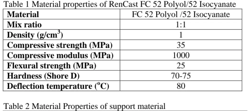
SDM is a layered manufacturing technique with a sequence of additive and subtractive processing steps for fabricating complex 3D parts (Fig. 2). This process was first developed by Carnegie Mellon University and Stanford University. Various materials, such as metals and polymers, can be fabricated by the SDM. Support material is used to support holes or undercut structures. In each layer, part or support material is deposited in approximate volume and CNC machined to the net shapes. After the part is completely built, the support material is removed chemically or thermally. In this research, room-temperature cured polymer (RenCast FC 52 Polyol/52 Isocyanate by Hunstman Advanced Material GmbH, Switzerland) is used as part material and wax (combination of 25% File-a-wax and 75% Protowax by Kindt-Collins Company, U.S.A.) is the support material. Their material properties are listed in Tables 1 and 2.
The support material at the end is removed by heating the bulk wax away and resolving the traces in BIOACT 280 (Petroferm Inc., U.S.A.) at 65
oC.
Fig.2. SDM Process[8].
Proceedings of the 10th Advances in Materials and Processing Technologies Oct. 7-11, 2007, Daejeon, Korea, pp. 1512-1521
Table 1 Material properties of RenCast FC 52 Polyol/52 Isocyanate
MaterialFC 52 Polyol /52 Isocyanate
Mix ratio
1:1
Density (g/cm3)
1
Compressive strength (MPa)
35
Compressive modulus (MPa)1000
Flexural strength (MPa)25
Hardness (Shore D)
70-75
Deflection temperature (oC)
80 Table 2 Material Properties of support material
Product
File-a-wax Protowax
Melting point (oC)
105 60
Casting temperature (oC)
130 80
Shrinkage (%)
2.6 0.46
Machinability
Good Fair
3. Component 1: Propeller 3.1 Propeller Design
The blade section of the propeller was based on NACA4412 airfoil. The 3D propeller was designed by the Turbomachine Lab at National Taiwan University of Science and Technology.
The angle of twist is 18
o, the stagger angle is 65
o, and the number of blade is three. The outer and inner diameters of the propeller are 15 mm and 5 mm, respectively. In order to attach to motor shaft, an axis with 3.6 mm in diameter and 5 mm in length was extended from the hub of the propeller. The 3D CAD model of the propeller was generated by the commercial solid modelling software, Pro/ENGINEER (Parametric Technology Corporation, U.S.A.). After the 3D model is constructed, we can use mirror function in the CAD to produce another propeller rotating in the reverse direction. The CAD models of the both propellers are shown in Fig. 3.
Fig. 3. CAD models of propellers rotating in opposite directions.
3.2 Propeller Fabrication
Process planning was required before fabrication, according to the SDM process principle.
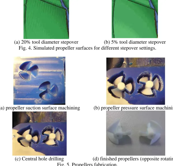
With SDM approach, there is no need to use a special fixture for pressure and suction surfaces machining. The machining paths were generated and simulated in UG/CAM (UGS Corp., U.S.A.). Suitable tool sizes and types for roughing and finishing cutting were first determined and necessary working parameters, such as cutting pattern, spindle speed, feed, and depth, were assigned. The machining results can be simulated first in UG. Two stepover settings (20% and 5% of tool diameter) were simulated for better surface smoothness as shown in Fig. 4 and found 5% is more suitable even though the machining time may increase slightly. The actual fabrication results are shown in Fig. 5 and the fabrication time is summarized in Table 3. If more
Proceedings of the 10th Advances in Materials and Processing Technologies Oct. 7-11, 2007, Daejeon, Korea, pp. 1512-1521
propellers are manufactured parallel, the casting time of part and support materials stay the same and only machining time is multiplied.
(a) 20% tool diameter stepover (b) 5% tool diameter stepover Fig. 4. Simulated propeller surfaces for different stepover settings.
(a) propeller suction surface machining (b) propeller pressure surface machining
(c) Central hole drilling (d) finished propellers (opposite rotating) Fig. 5. Propellers fabrication.
Table 3 Summary of propeller fabrication time
CNC milling timeRoughing Finishing Subtotal
Suction surface
8 min 20 min 28 min
Hub extended axis
5 min 2 min 7 min
Pressure surface
12 min 30 min 42 min
Central hole
3 min
Total 80 min
Part and support material casting time
Support material casting and curing
15 min
Part material mixing and casting5 min
Part material curing
60-90 min
Total 80-110 min
Proceedings of the 10th Advances in Materials and Processing Technologies Oct. 7-11, 2007, Daejeon, Korea, pp. 1512-1521
4. Component 2: Hull Structure
4.1 Hull Design and Assembly Strategies
The hull profile was designed with the help of STAR-CD CFD software (CD Adapco Group, U.S.A.). Two shrouds are added to the back of the main hull geometry with connecting ribs to conduct the flow, stabilize the vehicle, and protect the propellers. The CAD model of the hull structure, 65 mm x 40 mm x 32 mm, is shown in Fig. 6. In particular, the geometry of the shrouds is illustrated in Fig. 7. The dimensions of the shrouds are 17 mm in inner diameter, 10 mm long, and 1 mm thick. The clearance between the shroud and the propeller was set to be 1 mm.
Fig. 6. CAD of the hull structure.
17m m
1mm
10mm
1mm
Fig. 7. Back view (left) and side view (right) of the shrouds.
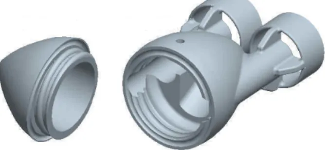
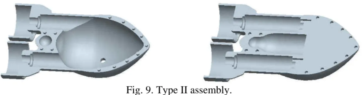
Two assembly strategies were investigated in this research. One is to divide the hull structure vertically at the maximum depth (Fig. 8) and to assemble the two parts by screwing together. In this scenario, threads (M25x2) are integrated in the hull structure and the difficulty in manufacturing is increased. The second approach is to split the hull horizontally (Fig. 9) and to seal by glue. Some alignment features on both halves were designed for assembly purpose.
The prototypes of both strategies were manufactured and compared in this research.
Fig. 8. Type I assembly.
Proceedings of the 10th Advances in Materials and Processing Technologies Oct. 7-11, 2007, Daejeon, Korea, pp. 1512-1521
Fig. 9. Type II assembly.
4.2 Hull Structure Fabrication for Type I Assembly
In Type I assembly, the hull structure was divided into front and back portions. The structure of the front portion is simpler with 3D profiles and threads, while the back portion contains more complicated features, such as shrouds with connecting reinforcement and internal structure.
Moreover, the motors should be embedded inside the back portion during the fabrication, since later motor assembly is not possible in this configuration. Therefore, the front and back portions were fabricated separately. The building direction was chosen to be placing the parts horizontally for few building layers and convenient machining in the SDM process. In addition, motors could be embedded much easier. The manufacturing steps of the front and back portions are shown in Figs. 10 and 11. The construction times are listed in Tables 4 and 5.
(a) Machine wax substrate to obtain the outside profile of the
lower segment
(b) Deposit part material and machine the undercut feature (c) Deposit wax and machine the complementary thread
profile
(d) Deposit part material and machine the internal geometry of the lower
segment
(e) Deposit wax and machine the internal geometry of the
upper segment
(f) Deposit part material and machine the outer profile of the upper segment and the
thread
(g) Remove the support material (wax) by BIOACT 280 to obtain the front portion
of the hull structure Fig. 10. Fabrication steps of the front portion of the hull structure.
Proceedings of the 10th Advances in Materials and Processing Technologies Oct. 7-11, 2007, Daejeon, Korea, pp. 1512-1521
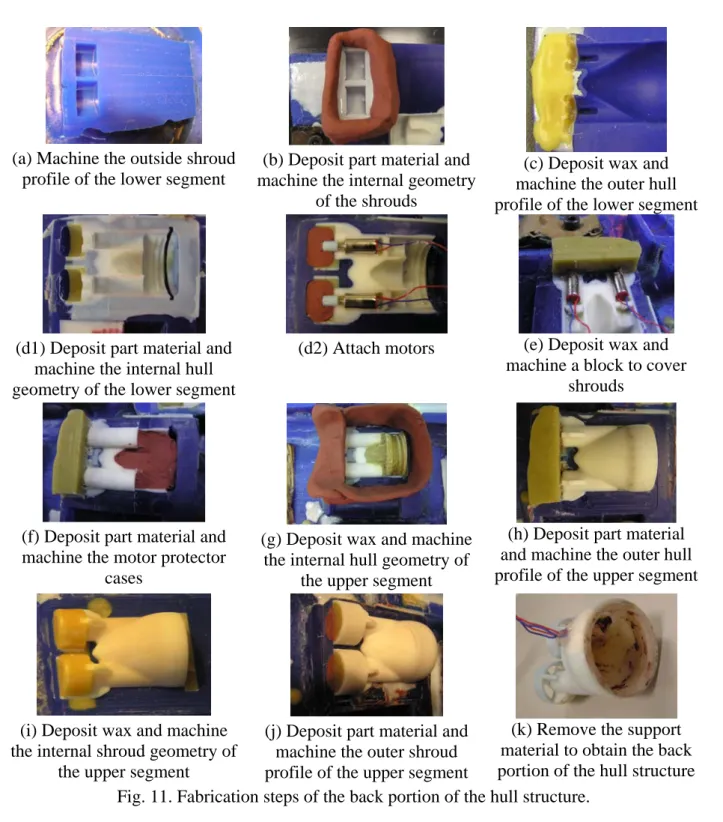
(a) Machine the outside shroud profile of the lower segment
(b) Deposit part material and machine the internal geometry
of the shrouds
(c) Deposit wax and machine the outer hull profile of the lower segment
(d1) Deposit part material and machine the internal hull geometry of the lower segment
(d2) Attach motors (e) Deposit wax and machine a block to cover
shrouds
(f) Deposit part material and machine the motor protector
cases
(g) Deposit wax and machine the internal hull geometry of
the upper segment
(h) Deposit part material and machine the outer hull profile of the upper segment
(i) Deposit wax and machine the internal shroud geometry of
the upper segment
(j) Deposit part material and machine the outer shroud profile of the upper segment
(k) Remove the support material to obtain the back portion of the hull structure Fig. 11. Fabrication steps of the back portion of the hull structure.
Table 4 Fabrication time of the front portion
Material casting and curing CNC milling
Step Part material Support material Roughing Finishing
(a)
N/A N/A 8 min 20 min
(b)
90~120 min N/A 15 min 10 min
(c)
N/A 10~15 min 10 min 20 min
(d)
90~120 min N/A 10 min 20 min
(e)
N/A 20~25 min 8 min 20 min
(f)
90~120 min N/A 10 min 30 min
Total 300~400 min 181 min
Proceedings of the 10th Advances in Materials and Processing Technologies Oct. 7-11, 2007, Daejeon, Korea, pp. 1512-1521
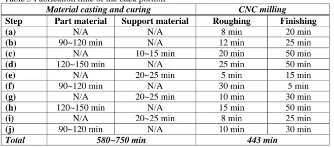
Table 5 Fabrication time of the back portion
Material casting and curing CNC milling
Step Part material Support material Roughing Finishing
(a)
N/A N/A 8 min 20 min
(b)
90~120 min N/A 12 min 25 min
(c)
N/A 10~15 min 20 min 50 min
(d)
120~150 min N/A 25 min 50 min
(e)
N/A 20~25 min 5 min 15 min
(f)
90~120 min N/A 30 min 5 min
(g)
N/A 20~25 min 10 min 30 min
(h)
120~150 min N/A 15 min 50 min
(i)
N/A 20~25 min 8 min 25 min
(j)
90~120 min N/A 10 min 30 min
Total 580~750 min 443 min
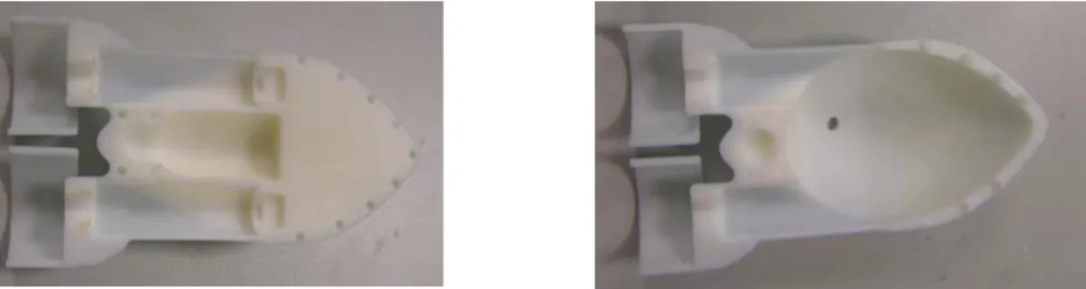
4.3 Hull Structure Fabrication for Type II Assembly
In Type II assembly, the hull structure was horizontally split into two halves with similar features and outer profiles except internal space allocation. For the SDM process, the layer slicing is the same for both halves, and only the last layer’s machining geometry is different.
Therefore, both halves can be fabricated at the same time to reduce material deposition and curing time, and can share some machining codes to save time of changing machining codes.
The fabrication steps are illustrated in Fig. 12 and the finished two halves of the hull structure after support material removal are shown in Fig. 13. The time spent in the process is summarized in Table 6.
(a) Machine the outside shroud profile
(b) Deposit part material and machine the internal geometry
of the shrouds
(c) Deposit wax and machine the outer hull
profile
(d) Deposit part material (e) Machine the internal hull geometry of the lower half of
the hull structure
(f) Machine the internal hull geometry of the upper
half of the hull structure Fig. 12. Fabrication steps of the two halves of the hull structure.
Proceedings of the 10th Advances in Materials and Processing Technologies Oct. 7-11, 2007, Daejeon, Korea, pp. 1512-1521
Fig. 13. Finished two halves of the hull structure.
Table 6 Fabrication time of the both halves of the hull structure
Material casting and curing CNC milling
Step Part material Support material Roughing Finishing
(a)
N/A N/A 8 min 20 min
(b)
90~120 min N/A 12 min 25 min
(c)
N/A 10~15 min 30 min 70 min
(d)
120~150 min N/A N/A N/A
(e)
N/A N/A 25 min 60 min
(f)
N/A N/A 25 min 40 min
Total 220~285 min 315 min
4.4 Discussion on Assembly Strategies
From the above investigation, both assembly strategies are achievable in the SDM process but may encounter resolution, material strength, and cleaning issues in other RP processes.
Comparing both assembly strategies, the total time consumed in manufacturing is the main concern in selection. In the SDM process, material deposition and curing usually occupies greater portion of time relative to machining steps. As a result, Type I assembly which divides the hull structure vertically spent about 25 hours, while Type II only needed 9 hours. The major reasons are the number of layers required in Type II is much fewer and both halves can be built at the same fabrication run. Under this time scale, it is considered faster and cheaper than other traditional approaches. The only disadvantage of Type II assembly is sealing by glue, which is not reversible. Since we do not need to disassemble the hull frequently, this issue is not prominent. Therefore, the Type II assembly strategy, which splits the hull structure horizontally, is considered to be a better approach in this case and is applicable to other similar applications.
5. Conclusion
In this research, components including propellers and the hull structure of a meso-scale underwater vehicle were fabricated by the SDM process, one of the rapid prototyping techniques.
Unlike other RP processes involving only deposition in each layer, SDM utilizes CNC machining to shape geometry after material deposition, hence, better resolution can be achieved.
3D propellers with smooth surfaces were successfully fabricated within 3 hours. The fabrication feasibility of the hull structure was investigated for two different assembly strategies—dividing the hull vertically and horizontally. The SDM process is proved to be suitable for both assembly types, and the Type II assembly is favored for less time and cost required. In conclusion, this research provides a solution to fabricate 3D complex components of the meso-scale underwater vehicles. The manufacturing approaches discussed in this research are applicable to other similar-scale underwater vehicles.
Proceedings of the 10th Advances in Materials and Processing Technologies Oct. 7-11, 2007, Daejeon, Korea, pp. 1512-1521
6. References
[1] Inter-Agency Committee on Marine Science and Technology, (http://www.marine.gov.uk/autosub.htm)
[2] The AUV Laboratory at Massachusetts institute of technology Sea Grant, (http://auvlab.mit.edu/vehicles/vehiclespec3.html)
[3] The Australian National University, (http://users.rsise.anu.edu.au/%7eserafina/2- Systems/Submersibles.html)
[4] M. Purcell, C. von Alt, B. Allen, T. Austin, N. Forrester, R. Goldsborough, and R. Stokey, New capabilities of the REMUS autonomous underwater vehicle, Proc. OCEANS 2000
MTS/IEEE Conference and Exhibition, Providence, Rhode Island, U.S.A., Vol. 1, 2000,147-151.
[5] B. Hobson, B. Schulz, J. Janet, M. Kemp, R. Moody, C. Pell, and H. Pinnix, Development of a micro autonomous underwater vehicle for complex 3-D sensing, Proc. OCEANS 2001.
MTS/IEEE Conference and Exhibition, Honolulu, Hawaii, U.S.A., Vol. 4, 2001, 2043-2045.
[6] K. Doty, A. Arroyo, C. Jantz, D. Novick, R. Pitzer, and A. Qaiyumi, An autonomous micro- submarine swarm and miniature submarine delivery system concept, Proc. Florida
Conference on Recent Advances in Robotics, Melbourne, Florida, U.S.A.,1998.[7] R. Merz, F. B. Prinz, K. Ramaswami, M. Terk, and L. Weiss, Shape deposition manufacturing, Proc. Solid Freeform Fabrication Symposium, Austin, Texas, U.S.A., 1994, 1-8.
[8] J. Kietzman, Rapid Prototyping Polymer Parts via Shape Deposition Manufacturing, Ph.D.
Thesis, Stanford University, 1999.
Proceedings of the 10th Advances in Materials and Processing Technologies Oct. 7-11, 2007, Daejeon, Korea, pp. 1512-1521