行政院國家科學委員會專題研究計畫 成果報告
磁振造影與腦磁波圖/腦電波圖之自動化整合
計畫類別: 個別型計畫
計畫編號: NSC92-2213-E-009-055-
執行期間: 92 年 08 月 01 日至 93 年 07 月 31 日
執行單位: 國立交通大學資訊工程學系
計畫主持人: 陳永昇
共同主持人: 陳麗芬,謝仁俊
計畫參與人員: 陳福慧、吳昭翰
報告類型: 精簡報告
處理方式: 本計畫可公開查詢
中 華 民 國 93 年 11 月 2 日
行政院國家科學委員會專題研究計畫成果報告
磁振造影與腦磁波圖
/腦電波圖之自動化整合
Automatic Co-registration of MRI and MEG/EEG
計畫編號:NSC 92-2213-E-009-055 執行期限:92 年 8 月 1 日至 93 年 7 月 31 日 主持人:陳永昇 國立交通大學 資訊工程學系 共同主持人:陳麗芬 國立陽明大學 神經科學研究中心 謝仁俊 行政院國軍退除役官兵輔導委員會 臺北榮民總醫院教學研究部 計畫參與人員:陳福慧 吳昭翰 國立交通大學 資訊工程學系 中文摘要 在本計畫中我們發展了自動化對位的技術, 可準確迅速地將由磁振造影所得到的三維腦部結 構影像與由腦磁波儀/腦電波儀所量測得的電生 理信號進行多元整合,以利後續進行腦部功能區 域分佈研究。這個多元整合技術的核心主要是在 利用立體電腦視覺的技術,自動估算磁振造影與 腦磁波儀/腦電波儀之間的頭部模型之座標系統 轉換關係,如此不但可省去傳統人工選點的麻煩 與耗時,並可降低因人工選點所導致的對位誤 差,能大幅提昇多元整合與腦部功能定位之準確 度。同時,運用這個技術之後受試者只需進行一 次磁振造影掃瞄,日後所多次量測的電生理信號 都可與先前掃瞄得的腦部結構影像進行整合,無 須每次量測電生理信號時都需搭配掃瞄磁振造影 影像,也就是同一受試者的一組三維腦部結構影 像可重複進行多組的電生理信號之整合,如此能 更加提升腦科學研究的效能。經由實驗我們也驗 證了這個方法的有效性。 關鍵詞:座標整合、磁振造影、腦磁圖、腦電圖 Abstract
Magnetic Resonance Imaging (MRI) and Magnetoencephalography (MEG) are noninvasive methods for structural and functional brain research pursuit. To correlate the obtained activity information with anatomical structure of the brain, we need to coregister the coordinate systems of both modalities. Conventionally, an operator is required to manually determine at least three landmark positions for the coordinate system coregistration. Major drawbacks of this kind of manual method include inter-rater variability and subjectivity, poor
repeatability, and intensive labor. In this work we propose an automatic coregistration method that can align MRI images and MEG data accurately and efficiently. Surface points of the face can be extracted from the MRI volume and then be projected to images captured by a calibrated trinocular camera rig. Coordinate system transformation between the MRI and the camera rig can be determined by minimizing the intensity differences among the projected face surface points on the images. Furthermore, the coordinate system transformation between the camera rig and MEG can be determined by aligning a set of face surface points whose 3D coordinates in both coordinate systems are obtained by using stereo vision technique and 3D digitizer, respectively. Concatenation of these two transformation results in the MRI-MEG coregistration. Another advantage of the proposed method is its superiority in longitudinal studies. Only one MRI scan is required for each subject and the MRI volume can be coregistered with the MEG data of consecutive MEG studies by using the proposed method. Our experiments have demonstrated the effectiveness of this method
Keywords: Co-registration, MRI, MEG, EEG 1. Introduction
Magnetoencephalography (MEG) is commonly used to investigate neuronal activity of human brain non-invasively. It provides excellent temporal resolution about 1 ms but lacks for anatomical information. Therefore, coregistration of MRI and MEG data in one image is necessary for localization and observation of neuronal activity over the subject’s cortex [1-3].
Fig. 2 Visible markers in MRI image
Coregistration includes several procedures to transform the coordinates of one modality into the coordinates of another modality [4]. In this study, we proposed a computer vision based technique to improve the coregistration result with the present methods. In principle, the MRI coordinate of MRI volume image is transformed into the MEG coordinate of MEG machine through the world coordinate system defined by external digitization system. First, transformation between the MEG and world coordinate is performed automatically using head position indicator (HPI). Because HPI is a coil and emits current to induce magnetic field which can be detected in MEG machine, it is identified in the MEG coordinate and also digitized in the world coordinate. Second, the world coordinate is transformed into the MRI coordinate once the transformation between these two coordinate systems is known. In the literature, coregistration methods can be classified into three major categories.
The first kind of method uses anatomical landmarks to guide the co-registration (Fig. 1). In this method, more than three recognizable and intrinsic landmarks [5] must be found in the MRI and world coordinate so the alignment error of both modalities resulted mainly from the difficulty for detecting the same points on the head (world coordinate) and in MR image (MR coordinate). This approach does not need extra external markers but it produces uncertain error from manual label of the landmarks in MR image.
The second kind of coregistration method uses external fiducial markers (such as oil filled markers, masks, and dental bite bars). These markers are visible in MR image (Fig. 2) and can be digitized on
a subject’s head. The external markers are identified much easily in the MRI and world coordinate [6, 7] but the subject may feel uncomfortable with markers stuck to his/her face thus may introduce confounding. This approach is not suitable for longitudinal studies because one MRI scan of a subject with extra markers is needed for each MEG measurement. Besides, it faces errors from detection of relatively large markers (about 3mm) in MR image.
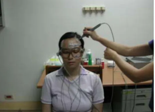
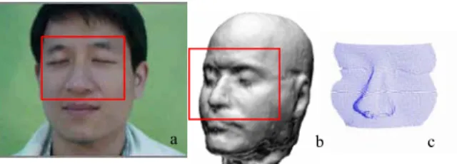
The third kind of method uses geometrical features of a subject to perform the alignment. The most common method is distance based alignment [1, 8, 9]. More than 500 points from a subject’s head is digitized manually (Fig. 3a) and the point set is rotated to the same orientation as the head surface on the MRI coordinate (Fig. 3b). Then, the distance between the point set and MRI head surface is minimized to coregister the world and MRI coordinates (Fig. 3c). This approach does not require fiducial markers and is suitable for longitudinal studies. However, manual digitization of many points is time consuming and alignment accuracy depends on uniform distribution of these points.
In this study, the camera-guided coregistration method is adopted to improve the disadvantage of the conventional methods. Using the proposed method, the coregistration is performed automatically without external markers and much manual labor. Then functional information with high temporal and spatial resolution is obtained.
2. Materials and methods
2.1. Overview
In MRI images, the point set of head surface (Fig. 4c) is extracted from the region of interest (ROI) (Fig. 4b) which also can be selected in camera images (Fig. 4a). Using initial guess of transformation matrix (WT
M), the surface point set in
the MRI coordinate (CM) is transformed into the
world coordinate (CW) (Fig. 5). Then, the point set in
Fig. 1 Manual selection of anatomical landmark
Fig. 3 (a) Original (b) orientation aligned (c)
the world coordinate is projected into three camera coordinates (CC) of different orientation [10]. The
image intensity of the point set is obtained from three cameras images. The difference of image intensity between camera images is minimized for the optimal transformation matrix (WT
M). Using
the transformation matrix, the points of head surface in the MRI coordinate are transformed into the world coordinate. Therefore MRI-MEG co-registration is performed through world coordinate system with the proposed technique.
2.2. Instrumentation
The MRI scan of the same subject was conducted using a Bruker 3T MR system (MedSpec 30/100, Germany). The 128 slices of T1-weighted image were obtained with Repetition Time (TR) 1800 msec, Echo Time (TE) 35 msec, in-plane matrix 256*256 pixels, field of view 230*230 mm2 and slice thickness 1.5 mm. In MRI volume, the ROI is selected interactively to extract surface points with the Matlab program.
Three SONY cameras (DFW-X700) fixed on a rod with suitable angle were separated from the same distance (Fig. 6). The whole camera set is put on the adjustable camera holder for the optimal height to take a picture of the subject’s face. The maximum spatial resolution of each camera is 1024
pixels * 768 pixels. Camera images are delivered to a computer with IEEE 1394 interface card.
2.3. Camera Calibration
Three cameras are well calibrated in Academic Sinica with the calibrated board (Fig. 7). There are several white circles of well-known size with black background on the calibrated board. The board with mechanic motor controlled by workstation can reach the desirable distance. Images of board are then captured for intrinsic and extrinsic parameters calculation for all cameras [11].
However, extrinsic camera parameters are affected by of camera movement and incorrect parameters result in coregistration error. Therefore, on-site calibration can assure the accuracy of camera before each experiment. On-site calibration is performed with one simple pattern (Fig. 8). There are 611 big circles with a diameter of 8mm and 14 small circles with a diameter of 5.6 mm in the picture so these circles of known position can be used for calibration of extrinsic camera parameters. In our study, on-site calibration for extrinsic camera parameters is performed before each experiment and the calibration error is less than 1mm.
b c a
Fig. 4 (a) The ROI in camera image is the same as
(b) the ROI in MRI image to extract (c) surface points in MRI
Fig. 5 The flowchart of transformation between the
MRI and world coordinate MT W MRI volume Surface point segmentation WT M CW CC World coordinate Camera image
CM Fig. 6 Three cameras on the camera holder
2.3. Optimization
In the beginning, the good initial guess is used to check the performance of whole procedure. Three obvious positions are selected and each position should be on the same location for MRI image and three camera images. With camera calibration parameters, three specific points on each camera image is transformed to the world coordinate. With three specific points, the transformation matrix between the MRI and the world coordinate is calculated as initial guess (WT
M). Therefore, the
surface points (XM) from the selected ROI in MRI
images can be transformed into the world coordinate with the initial guess. Under Lambertian assumption, the image intensity (I) of camera image points which are projected (Pi) from the world
coordinate should be the same for each camera (i,j). Then, the cross correlation coefficient of image intensity for these points between all three cameras is maximized to extract the optimal transformation matrix (WT
M) between the MRI and world
coordinate: WT ? M = argmaxW TM Ii
(
PiWTMXM)
Ij(
PjWTMXM)
(
)
2 XM∑
i, j ( )∑
Ii(
PiWTMXM)
2 XM∑
i∑
Using the optimal transformation matrix, the MRI-MEG co-registration can be performed through the world coordinate. The optimization procedure is iterative calculation using Nelder-Mead simplex (direct search) method [12] on Matlab.
3. Experimental results
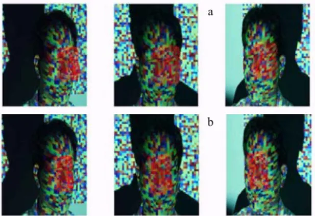
There are few intrinsic features in our camera pictures so a gradient color light is projected on a subject’s face to increase image texture. When the good initial guess is applied, the surface points from MRI images match the camera images. If the initial guess is shifted, the alignment error between the surface points and camera images is increased after several iterations. The alignment error results from poor difference of image intensity between neighbor pixels so the random color light is applied to increase image features. However, the random extent of light pattern affects co-registration result. The color light of optimal randomness is used to avoid much local minimum and keep image texture. After that, the result is close to the optimal one with shifted initial guess only along x axis (Fig. 9). Even with shifted initial guess both along x and y axis (Fig. 10), the co-registration result is still good using optimization twice. The optimization method with random color light is less sensitive to initial
Fig. 8 There are 611 big circles with a diameter
of 8mm and 14 small circles with a diameter of 5.6 mm in the picture. Therefore, on site calibration is performed with these circles of
known position.
Fig. 9 The MRI surface points (red points) with (a)
initial guess transformation matrix (shifted only on x-axis) (b) the optimal transformation matrix on three
camera images with suitable gradient color light.
a
b
Fig. 10 The MRI surface points (red points)
with (a) initial guess transformation matrix (b) the optimal transformation matrix on three
camera images with random color light
a
guess than gradient color light. In our preliminary result, the automatic coregistration between the MRI and world coordinate is performed well. Furthermore, the whole coregistration procedures are performed with home-made programs of Matlab and C code. These programs are integrated into Matlab code to improve its efficiency. Based on this coregitsration result, automatic MRI-MEG coregistration can be performed using the proposed technique.
4. Discussions
There are four issues to be discussed as following.
Accuracy of camera calibration
The relationship between camera and world coordinate is defined by camera calibration so it is important to assure the accuracy of camera calibration. If the camera calibration is correct, points on the center of circles in world coordinate transformed from two camera images should be projected on the center of circle in the other camera image (Fig. 8). Before experiment is conducted, the accuracy of camera calibration is checked with the method mentioned above. Besides, on-site camera calibration is applied in this study to avoid calibration error during the transportation [13].
Optimization algorithm
According to our preliminary data, the optimization method we used is fast but it is sensitive to initial guess. If worse initial guess is appiled, the alignment error is larger. Therefore a optimization method with few constraints on local minimum is better for our data [14, 15]. Furthermore, selection of objective function in optimization also affects coregistration result. If the objective function is tolerant to global difference of image intensity between three different cameras, the coregistration is performed with little disturbance.
Verification of the co-registration result
The phantom study will be applied for verification. The MEG phantom from Neuromag company can send electric current from known position. The anatomy image of MEG phantom is obtained by Computed Tomography (CT) to avoid damaging the electrical structure of the phantom by
MRI. The position of the current source obtained with the proposed method is compared with known position of the same current source. The comparison is to verify accuracy of the proposed method [16, 17].
Integration of programs
The core program for optimization is written in C code to increase processing speed but the other part is written in Matlab to easily build up graphic user interface (GUI). Matlab programs have ability to access C code through MEX functions so all programs are integrated into Matlab platform. The integrated program is not only user-friendly but the optimization process of the program still maintains fast. Hence, the whole system is performed on the same platform to improve its efficiency.
References
[1] Wang, B., et al., Head surface digitization and registration: a method for mapping positions on the head onto magnetic resonance images. Brain Topography, 1994.6(3):p.185-92.
[2] Carducci, F., et al., Multimodal integration of high-resolution EEG and functional magnetic resonance imaging data: a simulation study. Cortex, 2003.39(2):p.293-305.
[3] Kober H, G.P., Vieth J, Precise fusion of MEG and MRI tomography using a surface fit.
Biomedical Engineering, 1993.38(suppl):p.355-356.
[4] Besl, P.J.M., H.D., A method for registration of 3-D shapes. IEEE Transactions on Pattern Analysis and Machine Intelligence, 1992.14(2):p.239-256.
[5] Singh, K.D., et al., Evaluation of MRI-MEG/EEG co-registration strategies using
Monte Carlo simulation. Electroencephalography & Clinical Neurophysiology, 1997.102(2):p.81-5.
[6] Simpson, G.V., et al., Dynamic neuroimaging of brain function. Journal of Clinical Neurophysiology, 1995.12(5):p.432-49.
[7] Yoo, S.-S., Guttmann, Charles R.G.a, Ives, John R.b, Panych, Lawrence P.a, Kikinis, Rona, Schomer, Donald L.b, Jolesz, Ferenc A., 3D Localization of surface 10-20 EEG electrodes on high resolution anatomical MR images. Electroencephalography and Clinical Neurophysiology, 1997.102(4):p.335-339.
[8] Kozinska, D., F. Carducci, and K. Nowinski, Automatic alignment of EEG/MEG and MRI
data sets. Clinical Neurophysiology, 2001.112(8):p.1553-61.
[9] Kozinska, D.T., Oleh J.; Nissanov, Jonathan; Ozturk, Cengizhan, Multidimensional Alignment Using the Euclidean Distance Transform. Graphical Models and Image Processing, 1997.59(6):p.373-387.
[10] Chen, Y.-S., Liou, Lin-Gwoa, Hung, Yi-Pinga, Fuh, Chiou-Shannb, Three-dimensional ego-motion estimation from motion fields observed with multiple cameras. Pattern Recognition, 2001.34(8):p.1573-1583.
[11] Chen, Y.-S., Shih, Sheng-Wenb ,Hung, Yi-Pinga ,Fuh, Chiou-Shanna , Hung, Yi-Pinga, Simple and efficient method of calibrating a motorized zoom lens. Image and Vision Computing, 2001.19(14):p.1099-1110.
[12] DW, M., An algorithm for least squares estimation of nonlinear parameters. Journal of the Society for Industrial and Applied Mathematics, 1963.11(2):p.431-441.
[13] Tsai, R., A versatile camera calibration technique for high-accuracy 3D machine vision metrology using off-the-shelf TV cameras and lenses. IEEE Journal of Robotics and Automation, 1987.3(4):p.323-344.
[14] Paul Viola, W.M.W.I., Alignment by Maximization of Mutual Information. International Journal of Computer Vision, 1997.24(2):p.137-154.
[15] Weng, J.C., P. Herniou, M., Camera calibration with distortion models and accuracy evaluation. IEEE Transactions on Pattern Analysis and Machine Intelligence, 1992.14(10):p.965-980.
[16] Dale A., S.I., Improved localization of cortical activity by combining EEG and MEG with MRI cortical surface reconstruction: a linear approach. Journal of Cognitive Neuroscience, 1993.2(5):p.162-176.
[17] Huppertz, H.J., et al., Estimation of the accuracy of a surface matching technique for registration of EEG and MRI data. Electroencephalography & Clinical Neurophysiology, 1998.106(5):p.409-15.