國立交通大學
光電工程研究所
碩士學位論文
飛秒高功率光固子壓縮自啟式加波鎖模
掺鉺光纖雷射
Femtosecond High-Power Soliton
Compression of a Self-Started APM
Erbium-Doped Fiber Laser
研究生:林螢聰
指導教授:林恭如
飛秒高功率光固子壓縮自啟式加波鎖模掺鉺光纖雷射
Femtosecond High-Power Soliton Compression of a Self-Started APM
Erbium-Doped Fiber Laser
研 究 生:林螢聰 Student:Ying-Tsung Lin
指導教授:林恭如 老師 Advisor:Gong-Ru Lin
國 立 交 通 大 學
光 電 工 程 研 究 所
碩 士 論 文
A ThesisSubmitted to Institute of Electronics College of Engineering National Chiao Tung University
in partial Fulfillment of the Requirements for the Degree of
Master
In Electro-Optical Engineering
June 2006
Hsinchu, Taiwan, Republic of China
摘 要
論文名稱:飛秒高功率光固子壓縮自啟式加波鎖模掺鉺光纖雷射 校所別:國立交通大學光電工程研究所 頁數:1 頁 畢業時間:九十四學年度第二學期 學位:碩士 研究生:林螢聰 指導教授:林恭如 老師 關鍵詞:光固子效應壓縮、摻鉺光纖放大器、摻鉺光纖雷射、單模光纖、大有 效面積光纖 本論文,是利用非線性光學中的光固子效應壓縮飛秒光纖雷射產生一 個壓縮脈衝光。然而,利用光固子壓縮會造成脈衝品質的劣化,劣化的程度與 光固子階數成正比;為了去改善光固子壓縮的缺點,我們提出了利用大模面積 的高濃度掺鉺光纖來製作掺鉺光纖放大器,除了進一步縮短掺鉺光纖的長度之 外,更使得脈衝在被放大過程中,所產生的非線性效應能夠達到最小化。而在 脈衝被放大之前,我們利用單模光纖事先引入適當的負啾頻量,目的是要預先 補償在放大的過程中所引入的正啾頻量,使脈衝在放大的過程中能夠連續地窄 化。這樣的架構能夠降低光固子壓縮的階數與抑制底座的產生。另外,在放大 之後,我們選擇一段最佳的單模光纖長度,擷取出在光固子效應下最窄的脈 衝。利用這種設計可以獲得一個波形完整乾淨的壓縮脈衝,脈衝寬度為 56 飛 秒,放大壓縮後的峰值功率為 46 千瓦。最後,為了更進一步縮短脈衝寬度, 獲得更大的壓縮率,我們將單模光纖與大有效面積光纖結合成二階式的光固子 壓縮,其脈衝寬度可由原始的 300 飛秒壓縮到 30 飛秒,而脈衝的峰值功率也 得以有700 倍以上的放大。ABSTRACT
Title : Femtosecond High-Power Soliton Compression of a Self-Started APM Erbium-Doped Fiber Laser
Pages:1 Page
School:National Chiao Tung University
Department:Institute of Electro-Optical Engineering
Time:June, 2006 Degree:Master
Researcher:Ying-Tsung Lin Advisor:Prof. Gong-Ru Lin
Keywords : Soliton-Effect Compression, Erbium-Doped Fiber Amplifier, Erbium-Doped Fiber Laser, Single-Mode Fiber, Large-Effective-Area Fiber
Femtosecond soliton effect compression is investigated to obtain pulses from passively mode-locked fiber lasers. Due to the inherent drawback of soliton-effect compression that the pulse quality Qc (defined as the energy ratio of the central pulse
to total pulse) is decreasing monotonically from its ideal value of 1 as the soliton order N increases, we propose a new concept of using a simplified Erbium-doped fiber Amplifier (EDFA) based all-fiber compressor. A very short but highly-doped large-mode-field-area (LMFA) Er-doped fiber is employed to minimize the nonlinear process occurred during the high-power amplification of Erbium-doped fiber laser (EDFL) pulses. By using a pre-chirped single-mode fiber (SMF) segment for controlling the chirp of fiber laser pulse before launching into the Er-doped fiber and the last compression stage. Optimized pre-chirping, amplification and compression of the fiber laser pulse can be achieved under the fine adjustment on both the lengths of the SMF segments before and after the LMFA-EDFA. We primarily report that a 100% energy confinement within the central portion of the compressed soliton pulse is obtained, which exists a peak power of 46 kW and a pulsewidth of 56 fs. A additional compression stage is employed to further shorten the amplified EDFL pulsewidth and to achieve largest compression ratio, which combines the SMF and large-effective-area fiber (LEAF) to perform a dual-stage soliton compression link. As a result the pulsewidth shrinks from 300 fs to 30 fs associated with a maximum peak-power amplification ratio of >700.
ACKNOWLEDGEMENT
在這兩年的碩士生涯中,首先要特別對我的指導教授 林恭如老師在研究 的過程中不斷的給予支持與耐心的指導表達敬意與感謝之意,使我在求學態度 受益良多。 感謝實驗室張詠誠、林俊榮、廖育聖、吳銘忠、邱奕祥、林齊冠與陳家陽 學長對我不厭其煩的教導,及與我同甘共苦的張峻源同學在實驗與課業研究上 給予的協助,在遇到挫折時給我的最大支持與鼓勵,另外感謝學弟游昆傑在實 驗上的協助。最後我要感謝我最摯愛的家人,尤其是在背後默默支持我的父母 親,以及其他的好朋友,對於你們全力的支持與關愛,僅致上無限的敬意與感 激。CONTENTS
Page
Abstract (in Chinese)
iAbstract (in English)
iiAcknowledgement
iiiContents
ivList of Figures
viChapter 1 :
Introduction1.1 Short-Pulse Fiber Lasers 1
1.2 Fiber Lasers Pulse Compression 3
1.3 Motivation 5
1.4 Structure of this thesis 6
1.5 References 6
Chapter 2 :
Principle of the Experiment2.1 Principle of Self-started Additive Pulse Mode-Loking 11
2.1-1 Nonlinear Polarization Rotation 11
2.1-2 Stretched-pulse laser 12
2.2 Principle of Soliton-Effect Pulse Compression 13
2.2-1 Physical Mechanism 13
2.2-2 SPM-Induced Spectral Broadening 15
2.2-3 Soliton-Effect Compressors 17
2.2-4 Intrapulse Raman Scattering 19
2.3 References 20
Chapter 3 :
Dual-stage soliton compression of a self-started additive pulse mode-locked erbium-doped fiber laser for 48 fs pulse generation3.1 Introduction 24
3.2 Experimental Setup 25
3.3 Results and Discussion 26
3.3.1 SMF Compression 27
3.3.2 LEAF Compression 28
3.3.3 SMF+LAEF Compression 28
3.4 Conclusions 30
3.5 References 30
Compression with a Pre-Chirped Large-Mode-Area Er-Doped Fiber Amplifier
4.1 Introduction 37
4.2 Design and Implementation of EDFL and LMFA-EDFA 39 4.3 Pre-chirped Amplification and Compressing Results 41 4.4 Comparisons of Previous Results and Our Work 43
4.5 Conclusion 44 4.6 References 45
Chapter 5 :
Summary 5.1 Summary 52 5.2 Future work 53 Curriculum Vitae 54 Publication list 55LIST OF FIGURES
Fig. 2.1 Structure of nonlinear polarization rotation... ... Fig. 2.2 Mechanism of P-APM... ... Fig. 2.3 Structure of stretch-pulse laser... Fig. 2.4 Variation of compression factor Fc, optimum fiber length zopt,
and quality factor Qc with the parameter N. Data points correspond to experiments performed with 320-m (crosses) and 100-m (solid dots) fober. (After Ref [2.4]).... ... Fig. 3.1 Experimental setup of the APM-EDFL system with an externally
dual-stage soliton compressor... Fig. 3.2 Auto-correlated pulse traces and corresponding spectra (inset) of
the original and EDFA amplified pulses... Fig. 3.3 Auto-correlation traces of the APM-EDFL pulse after the EDFA,
the SMF, the LEAF, and the SMF+LEAF link. ... Fig. 3.4 The compressed pulsewidth as a function of SMF
length ………... Fig. 3.5 Normalized spectra of the APM-EDFL pulse after the EDFA,
the SMF, the LEAF, and the SMF+LEAF link... Fig. 3.6 The compressed pulsewidth as a function of LEAF length…… Fig. 4.1 Setup of a self-started passively nonlinear-polarization-rotation
mode-locked EDFL system.
Fig. 4.2 Setup of a pre-chirped EDFA based power-amplified soliton compressor.
original, the pre-chirped and the amplified/compressed pulses. Fig. 4.4 Compressed pulsewidth and pulse quality as a function of the
SMF length.
Fig. 4.5 Autocorrelation traces and correspond to pulse spectra of the initial and the output of LEAF fiber.
Table 3.1 The optical parameters of the SMF and LEAF at 1560nm. Table 4.1 The optical parameters of the single mode very highly
Er-doped fiber.
Chapter 1
Introduction
1.1 Short-Pulse Fiber Lasers
Q-switching and mode locking are known as two techniques used for generating short optical pulse from lasers [1.1-1.3]. Q-switched fiber laser obtained by using an intracavity acousto-optic modulator was demonstrated as early as 1986 to obtain [1.4]. Up to now, Q-switching remains a useful technique for fiber lasers since it can generate high peak-power (> 1kW) pulse with tunable wavelengths over a wide range covering the entire gain spectrum [1.5-1.7]. In 1999, to has been reported that Q-switched pulses from a double-clad Yb-fiber laser could be tunable from 1060 to 1100 nm while maintaining peak powers as large as 2 kW [1.5]. By using, a Fabry-Perot etalon with a free spectral range of 0.535 nm and a finesse of 76, Q-switched pulses can be generated from an EDFL at more than 90 distinct wavelengths simultaneously [1.6]. Pulse energy as high as 2.3 mJ was generated at a repetition rate of 500 Hz from a cladding-pumped Yb-doped fiber laser made Q-switching scheme [1.7]. However, Q-switching usually produces broad optical pulses (~100 ns). In contrast, mode-locking can generate pulsewidth of shorter than 100 fs. Early experiments on the Nd-doped fiber lasers produced pulsewidth of >1-ns [1.8]. A short pulsewidth of 120 ps was obtained in 1988 [1.9]. Later on, the researching interests were focused on the development of mode-locked EDFLs for potential applications in optical communication systems [1.10, 1.11].
The most common technique for active mode-locking of fiber lasers makes use of an acousto-optic / electro-optic amplitude or phase modulator. In 1989, mode-locked
fiber laser pulsewidth as short as 4-ps pulses was generated using a ring cavity with 2-km standard single-mode fiber (SMF) of large anomalous GVD [1.12]. The generation of ultrashort pulses relies on the soliton compressing effect. The pulse- repetition rate was extended to 30 GHz by using a high speed LiNbO3 modulator in
1990 [1.13]. Ring cavity design was demonstrated with an intracavity isolator for unidirectional operation. It was reported in 1992 that a fiber laser with transform-limited 3.5-10-ps pulsewidth and a time-bandwidth product of 0.32 at repetition rates up to 20 GHz [1.14], which has been employed for soliton communication at bit rate up to 8 Gb/s.
Passive mode-locking is an all-optical nonlinear technique capable of producing ultrashort optical pulses without requiring any active component inside the laser cavity. It makes use of a nonlinear device whose response to an entering optical pulse is intensity dependent such that the exiting pulse is narrower than the input pulse. Several implementations of this basic idea have been used to make passively mode-locked fiber lasers. Nonlinear amplifying-loop mirrors (NALMs) were first used in 1991 for mode-locking the fiber lasers [1.15, 1.16]. Fundamental soliton pulsewidth of shorter than 0.4 ps were generated from fiber laser pumped by Ti:sapphire laser [1.15]. Subsequently, 290-fs pulses were produced from an EDFL pumped by 1.48-um semiconductor lasers [1.16] with a mode-locking threshold of only 50 mW. Once the mode-locking is initiated, the pump power could further be decreased 10mW. Shorter pulse with energy as high as 0.5 nJ can be obtained by stretching the pulse during its amplification in the erbium-doped fiber with normal dispersion at the operating wavelength [1.17]. In addition, the fiber laser pulsewidth can be compressed down to 125 fs by using a long dispersion-shifted fiber inside the cavity. Both the central wavelength and the spectral width of the mode-locked fiber
laser pulses were tunable by adjusting intracavity the polarization-controllers.
On the other hand, the nonlinear polarization rotation technique was primarily used for passive mode-locking the fiber lasers since 1992 [1.18, 1.19], which generates stable and self-started pulse-train of subpicosecond pulsewidth at a 42-MHz repetition rate [1.18]. Further improvements occurred under the control of anomalous GVD within the laser cavity that limits both the width and the energy of mode-locked pulses. A premier demonstration of 76-fs pulsewidth (with 90-pJ energy and 1kW peak power) generated from a ring-cavity EDFL with a normal GVD has been reported in 1993 [1.19].
1.2 Fiber Lasers Pulse Compression
In viewing the envelopment of fiber lasers, it is seen that the pulse compression techniques are important for generating ultra-short pulses. Typically, the soliton-effect [1.20-1.22] and the adiabatic pulse compression techniques [1.23-1.26] can be utilized. Both techniques perform compression by manipulating the nonlinear propagation behavior of high-powered pulses in dispersive optical fibers. Soliton-effect compression can achieve high pulse-compression ratio with short fiber length. Ahmed et al. [1.22] compressed a 3.6-ps pulse down to 185 fs by propagation it along 30-m SMF. A drawback is that the pulse quality at optimized compressing point is poor since a significant portion of the pulse energy is spreading into a broad pedestal, which not only distorts the pulse shape but also makes the compressed pulse unstable due to the nonlinear interaction between the pedestal and the central peak. Therefore, the compression of fundamental soliton without pedestal using the adiabatic compression technique is of great interest. Under the adiabatic condition, the compressed pulse remains as fundamental soliton with its energy equivalent to that of the initial soliton.
Azimov et al. [1.27] and Blow et al. [1.28] have shown that such kind of soliton compression can be achieved by using dispersion-decreasing optical fibers (DDF). In an early experiment, a 130-fs pulsewidth were compressed to 50 fs in a 10-m DDF segment [1.23]. Larger compression ratios were realized in 1992 by [1.24] transmitting the fiber laser pulses through a 1.6-km fiber with a dispersion decreased from 10 to 0.5 ps/(km-nm), providing a compressing ratio as high as 16. In another experiment, 630-fs pulses were compressed down to 115 fs by using a fiber whose dispersion decreased from 10 to 1.45 ps/(km-nm) over a length of 100 m [1.25].
On the other hand, many applications require optical pulses with high energies that are not readily available from the laser producing the pulse train. It is then necessary to amplify the pulse externally by using one or more amplifiers. Chirped-pulse amplification has emerged particularly for this purpose since 1993. In general, mode-locked fiber lasers can produce pulses shorter than 1 ps with an energy of < 0.1nJ. A amplifying such pulses in an EDFA, although raises the energy level but the nonlinear effects occur during amplification and limit the pulse quality. It is thus necessary to stretch the pulse by a factor of 100 or larger before amplification, and further compress the amplified pulse back using a suitable compressor [1.29-1.31]. Such a scheme was demonstrated by using bulk gratings in 1994 and produced 800-fs pulse with energy of 100 nJ [1.29]. Bulk gratings were subsequently replaced by chirped fiber gratings to implement a compact, all-fiber based system. For example, a chirped fiber grating was employed to stretch the pulsewidth from 330 fs to 30 ps before amplification, while the second grating recompressed the amplified pulse back to 408 fs [1.30]. Alternatively, the pulse energy was boosted to 20 nJ by using a cladding-pumped fiber amplifier [1.31]. In both experiments, the quality of compressed and amplified pulses deteriorated at energy levels beyond 5 nJ due to the
nonlinear effects inside the compressor grating. On the other hand, the photonic bandgap fiber (PBF) based all-fiber compressor [1.32, 1.33], inevitably meet problems such as the difficulty in fusion-splicing with other standard optical fibers at a high efficiency. In addition, the GVD of this fiber is too large to optimize their lengths easily. The large dispersion slope of the PBF also makes the nonlinear chirp that cannot be compensated completely. There drawbacks make the pulsewidth and peak power remaining at 1ps and few kW, respectively. More recently, a highly doped EDF [1.34, 1.35] was employed to shorten the EDF length and to reduce the high-order nonlinear effect during pulse amplification and compression processes in EDFA and SMF based soliton compressor, respectively. To date, the ultrashort pulsewidths of 34 fs [1.34] and 43 fs [1.35] were obtained with peak power of 140 and 43 kW, respectively, at the cost of low confinement ratios (with pulses energies of 55% and 39% remaining in central peaks) and uncompressed pulse pedestal.
1.3 Motivation
Many applications require optical pulses with high energies that are not readily available from the fiber laser producing the pulse train. It is then necessary to amplify the fiber laser pulse externally by using amplifiers. In this thesis, a self-started additive pulse mode-locked (APM) Er-doped fiber laser (EDFL) to produce laser pulses with average power~1mW, pulsewidth of 300 fs and peak power of 80 W. Nonetheless, the application of such a fiber laser source is limited because of its lower output power and large pulsewidth. The target is to produce a pedestal-free fiber laser pulse with its pulsewidth of 100 fs and peak power of 50 kW, for potential applications in fields of the THz-wave generation and detection, and supercontinuum spectrum generation for bio-photonic applications. To meet these demands, we try to combine
the self-state APM-EDFL, Er-doped fiber amplifier (EDFA), SMF and large effect area fiber (LEAF) for pre-chirping, amplifying, and compressing the fiber laser pulses.
1.4 Structure of this thesis
Chapter 1 is an introductory chapter consists of the introduction to mode-locked fiber lasers, soliton-effect compression and the motivation of our research. Chapter 2 describes the principle of self-started APM and the nonlinear effects in optical fiber. Chapter 3 discusses the amplification and compression of self-started APM fiber laser pulse in a normal EDFA. In chapter 4, a home-made EDFA with a large-mode-field-area highly Er-doped fiber is employed to generate high-power soliton compressed pulses with a reduced high-order nonlinear effect. At last, Chapter 5 concludes our experimental results and gives future direction.
1.5 References
[1.1] A. E. Siegman, Lasers (University Science Books, Mill Valley, CA,1986)
[1.2] W. T. Silfvast, Laser Fundamentals (Cambridge University Press, New York, 1996)
[1.3] O. Svelto, Principles of Lasers, 4th ed. (Plenum, New York, 1998).
[1.4] L. Reekie, R. J. Mears, S. B. Poole, and D. N. Payne, “Tunable Single-Mode Fiber Lasers,” J. Lightwave Technol. LT-4, 956 (1986).
[1.5] C. C. Renaud, R. J. Selvas-Aguilar, J. Nilsson, P. W. Turner, and A. B. Grudinin, “Compact high-energy Q-switched cladding-pumped fiber laser with a tuning range over 40 nm,” IEEE Photon. Technol. Lett. 8, 976 (1999).
[1.7] J. A. Alvarez-Chavez, H. L. Offerhaus, J. Nilsson, P. W. Turner, W. A. Clark-son, and D. J. Richardson, “High-energy, high-power ytterbium-doped Q-switched fiber laser,” Opt. Lett. 25, 37 (2000).
[1.8] I. P. Alcock, A. I. Ferguson, D. C. Hanna, and A. C. Tropper, “Tunable, continuous-wave neodymium-doped monomode-fiber laser operating at 0.900 - 0.945 and 1.070 - 1.135 Mum,” Opt. Lett. 11, 709 (1986).
[1.9] I. N. Duling, L. Goldberg, and J. F. Weller, “High-power, mode-locked Nd:fibre laser pumped by an injection-locked diode array,” Electron. Lett. 24, 1333 (1988).
[1.10] M. E. Fermann, A. Galvanauskas, G. Sucha, and D. Harter, “Fiber-lasers for ultrafast optics,” Appl. Phys. B 65, 259 (1997).
[1.11] L. E. Nelson, D. J. Jones, K. Tamura, H. A. Haus, and I. P. Ippen, “Ultrashort-Pulse Fiber. Ring Lasers,” Appl. Phys. B 65, 277 (1997).
[1.12] J. D. Kafka, T. Baer, and D. W. Hall, “Mode-locked erbium-doped fiber laser with soliton pulse shaping,” Opt. Lett. 14,1269 (1989).
[1.13] A. Takada and H. Miyazawa, “30 GHz picosecond pulse generation from actively mode-locked erbium-doped fiber laser,” Electron. Lett. 26, 216 (1990). [1.14] H. Takara, S. Kawanishi, M. Saruwatari, and K. Noguchi, “Generation of highly
stable 20 GHz transform-limited optical pulses from actively mode-locked Er-doped fibre lasers with an all-polarisation maintaining ring cavity,” Electron.
Lett. 28, 2095 (1992).
[1.15] I. N. Duling Ⅲ, “All-fiber ring soliton laser mode locked with a nonlinear mirror,” Opt. Lett. 16, 539 (1991).
[1.16] M. Nakazawa, E. Yoshida, and Y. Kimura, “Low threshold, 290 fs erbium-doped fiber laser with a nonlinear amplifying loop mirror pumped by InGaAsP laser
diodes,” Appl. Phys. Lett. 59, 2073 (1991).
[1.17] T. O. Tsun, M. K. Islam, and P. L. Chu, “High-energy femtosecond figure-eight fiber laser,” Opt. Commun. 141, 65 (1997).
[1.18] K. Tamura, H. A. Haus, and E. P. Ippen, “Self-starting additive pulse mode-locked erbium fibre ring laser,” Electron. Lett. 28, 2226 (1992).
[1.19] K. Tamura, E. P. Ippen, H. A. Haus, and L. E. Nelson, “77-fs pulse generation from a stretched-pulse mode-locked all-fiber ring laser,” Opt. Lett. 18, 1080 (1993).
[1.20] L. F. Mollenauer, R. H. Stolen and J. P. Gordon, “Experimental Observation of Picosecond Pulse Narrowing and Solitons in Optical Fibers,” Phys. Rev. Lett. 45, 1095 (1980).
[1.21] J. T. Ong, R. Takahashi, M. Tsuchiya, S. H. Wong, R. T. Shara, Y. Ogawa and T. Kamiya, “Subpicosecond soliton compression of gain switched diode laser pulses using an erbium-doped fiber amplifier,” IEEE J. Quantum Electron. 29, 1701 (1993)
[1.22] K. A. Ahmed, K. C. Chan and H. F. Liu, “Femtosecond pulse generation from semiconductor lasers using the. soliton-effect compression technique,” IEEE J.
Quantum Electron. 1, 592 (1995).
[1.23] S. V. Chernikov and P. V. Mamyshev, “Femtosecond soliton propagation in fibers with slowly decreasing dispersion,” J. Opt. Soc. Am. B 8, 1633 (1991) [1.24] S. V. Chernikov, D. J. Richardson, E. M. Dianov and D. N. Payne, “Picosecond
soliton pulse compressor based on dispersion decreasing fibre,” Electron. Lett. 28, 1842 (1992)
[1.25] S. V. Chernikov, E. M. Dianov, D. J. Richardson and D. N. Payne, “Soliton pulse compression in dispersion-decreasing fiber,” Opt. Lett. 18, 476 (1993).
[1.26] P. V. Mamyshev, P. G. J. Wigley, J. Wilson and G. I. Stegeman, “Adiabatic compression of Schrödinger solitons due to the combined perturbations of higher-order dispersion and delayed nonlinear response,” Phys. Rev. Lett. 71, 73 (1993).
[1.27] B. S. Azimov, Izv. Akad. Nauk, “self compression of ultra-short optical pulses in a fiber-amplifier system,” lzv. Akad. Nauk. ser. fiz. 50, 2268 (1986)
[1.28] K. J. Blow, N. J. Doran and D. Wood, “Suppression of the soliton self-frequency shift by bandwidth-limited amplification,” J. Opt. Soc. Am. B 5, 1301 (1988) [1.29] M. E. Fermann, A. Galvanauskas, and D. Harter, “All-fiber source of 100-nJ
subpicosecond pulses,” Appl. Phys. Lett. 64, 1315 (1994).
[1.30] A. Galvanauskas, M. E. Fermann, and D. Harter, “All-fiber femtosecond pulse amplification circuit using chirped Bragg gratings,” Appl. Phys. Lett. 66, 1053-1055 (1995).
[1.31] J. D. Minelly, A. Galvanauskas, M. E. Fermann, D. Harter, J. E. Caplan, Z. J. Chen, and D. N. Payne, “Femtosecond pulse amplification in cladding-pumped fibers,” Opt. Lett. 20,1797 (1995).
[1.32] C. J. S. de Matos, J. R. Taylor, T. P. Hansen, K. P. Hansen, and J. Broeng, “All-fiber chirped pulse amplification using highly-dispersive air-core photonic bandgap fiber,” Opt. Express 11, 2832 (2003).
[1.33] C. J. S. de Matos and J. R. Taylor, “Multi-kilowatt, all-fiber integrated chirped-pulse amplification system yielding 40× pulse compression using air-core fiber and conventional erbium-doped fiber amplifier,” Opt. Express 12, 405 (2004).
[1.34] J. W. Nicholson, A. D. Yablon, P. S. Westbrook, K. S. Feder, and M. F. Yan, “High power, single mode, all-fiber source of femtosecond pulses at 1550 nm and
its use in supercontinuum generation,” Opt. Express 12, 3025 (2004).
[1.35] J. Takayanagi, N. Nishizawa, H. Nagai, M. Yoshida, and T. Goto, “Generation of high-power femtosecond pulse and octave-spanning ultrabroad supercontinuum using all-fiber system,” IEEE Photon. Technol. Lett. 17, 37 (2005).
Chapter 2
Principle of the Experiment
2.1
Principle of Self-started Additive Pulse Mode-Loking
2.1-1 Nonlinear Polarization Rotation
Nonlinear polarization rotation can occur in an optical fiber when the initial polarization state is elliptical due to the Kerr effect in glass [2.1, 2.2]. The propagation equation of the CW circular polarized light in the isotropic Kerr medium can be written as :
(
)
(
c cc)
cc c c cc c E E E iK E E E E iK z 2 2 cc 2 2 c 2 E 2 E + − = ∂ ∂ + − = ∂ ∂The solution of the above equations is
( )
[
( ) ( )]
( )
( )
[
( ) ( )]
( )
0 0 2 2 2 2 0 0 2 0 2 0 cc z E E iK cc c z E E iK c E e z E E e z E cc c cc c + − + − = =So the state of an elliptical polarized light (Ec 2 ≠ Ecc 2) will be rotated as shown in
Fig. 2-1. The rotated angle is proportional to the propagation distance and the intensity difference.
Nonlinear polarization rotation relies on the intensity-dependent rotation of an elliptical polarization state in a length of optical fiber. With proper settings of the initial polarization ellipse and the phase bias, pulse shortening can occur with the presence of a polarized element. Fig 2-2 shows how nonlinear polarization rotation can be used in conjunction with bulk polarization optics to obtain an artificial fast
polarized and then made elliptically polarizated with a quarter-wave plate. The light then passes through an optical fiber where ellipse rotation occurs and the peak of the pulse rotates more than the pulse wings. At the output of the fiber, the half-wave plate is oriented in such a way that the peak of the pulse passes through the polarizer while the wings of the pulse are extinguished. In this way achieving pulse shortening is achieved.
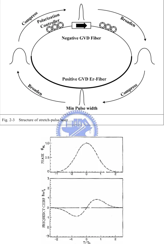
2.1-2 Stretched-pulse laser
Soliton lasers have inherent practical limits on their pulse width and pulse energy by the area theorem, due to the spectral sideband generation and saturation of the APM effect. Because the energy of a soliton is proportional to the product of the peak power and the pulse width, the energy is thus limited when either the peak power or pulse width is limited.
To overcome this difficulty, the stretched-pulse technique was introduced, where an all fiber Polarization-APM ring cavity is comprised of segments of alternately large positive- and negative-dispersion fiber, as shown in Fig 2-3. The single mode fiber has negative dispersion while the Er-fiber has positive dispersion. If the net dispersion is zero, the pulse width is shortest in the middle and is largest at the joints of the positive- and negative- dispersion fiber. Because of the periodic variation of the pulse width in the cavity, the accumulation of nonlinear phase shift can be reduced and thus the pulse energy can be increased. A mode-locked laser with short pulse width and high peak power thus can be obtained.
2.2 Principle of Soliton-Effect Pulse Compression
2.2-1 Physical Mechanism
The basic idea behind the optical pulse compression is borrowed from the chirp radar where the chirped pulses at microwave frequencies are compressed by passing them through a dispersive delay line. The physical mechanism can be understood by referring to [2.4], where propagation of the chirped optical pulse in a linear dispersive medium. If the initial chirp of the laser pulse is in opposite direction to that imposed by group-velocity dispersion (GVD) in the optical fiber, which tends to cancel each other, and results in an shorten pulsewidth as compared with the input one.
To see how such cancellation can produce shorter pulses, consider the propagation of a chirped Gaussian pulse inside an optical fiber. The optical field after a distance z can be written as
( )
[
(
)
]
(
[
(
)
)
]
⎭ ⎬ ⎫ ⎩ ⎨ ⎧ + − + − + − = − iC i T T iC iC i T z U 1 1 2 1 exp 1 1 , 2 0 2 2 1 ξ ξ , (2.2.1)where T= t-z/vg is the reduced time, T0 is the input pulse width, C is the initial chirp. The propagation distance ξ=z/LD is normalized to the dispersion lengthLD =T02 β2 .
For an unchirped pulse (C=0), the GVD-induced chirp varies linearly across the pulse. This can be verified from Eq. (2.2.1) by calculating the chirp usingδω =−∂φ ∂T. It
is easy to conclude that the input pulse should also be linearly chirped for maximum chirp cancellation.
Equation (2.2.1) can be used to find the compression factor Fc=T0/Tp as a function of propagation distance, where Tp is the width of the compressed Gaussian pulse. It is given by the simple expression
( ) (
[
)
2 2]
121+ + −
= ξ ξ
ξ sC
where s=sgn(β2)=±1, depending on the nature of GVD. This equation shows that
pulse is compressed only if sC<0. This condition just states that chirp cancellation occurs only if the initial chirp and GVD-induced chirp are of opposite kinds. Positively chirped pulses (C>0) require anomalous GVD for compression (and vice versa).
Equation (2.2.2) also shows that the shortest pulse is obtained only at a specific distance given by
(
1 C2)
C +
=
ξ . The maximum compression factor at that
distance is also fixed by the input chirp and is Fc= (1+C2). This limit is easily
understood by noting that spectrum of a chirped input pulse is broader by a factor of
1+C2 compared with that of an unchirped pulse. In time domain, different frequency
components of the pulse travel at different speeds under the presence of GVD. To compress the input pulse, a positive chirp (frequency increasing toward trailing side) is required to experience an anomalous (or negative) GVD in order to delay its red-shifted leading edge. In contrast, a negatively chirped pulse (frequency decreasing toward trailing side) requires a normal (or positive) GVD to slow down its blue-shifted leading edge.
Typically, the free-space propagated negatively chirped pulses were transmitted through liquids or gases to experience normal GVD. In the case of positively chirp pulses, a grating pair was found to be most suitable for providing anomalous GVD. In the case of positively chirp pulses, a grating pair was found to be most suitable for providing anomalous GVD. Both the aforementioned experiments induce pulse compression without any nonlinear optical effects.
The nonlinear pulse compressors based on the nonlinear effects in optical fibers can be classified into two categories, referred to here as fiber-grating compressors and soliton-effect compressors. In a fiber-grating compressor, the pulse is propagated in
normal-dispersive fiber and then externally compressed by a grating pair. The role of fiber is to impose a inear positive chirp on the pulse through a combined effect of the self-phase modulation (SPM) and GVD. The free-space grating pair then provides an anomalous GVD required for compressing the positively chirped pulses. Alternatively, the soliton-effect compressor which consists of only a suitable length of fiber is selected to compress the input pulse propagates through interplay between SPM and GVD. Compression occurs because of an initial pulse-narrowing phase through which all higher-order solitons go before the input shape is restored after one soliton period. The compression factor is correlated with the peak power of the input pulse that determines the soliton order N [2.4]. The two types of compressors are complimentary and generally operated in different wavelength regions with a demarcation governed by the zero-dispersion wavelength at about 1.3 nm in silica fibers. That is, the fiber-grating compressor is useful to compress pulse in the visible and near-infrared regions, whereas the soliton-effect fiber compressor is useful in the range of 1.3-1.6um.
2.2-2 SPM-induced Spectral Broadening
The propagation in the limit β2 =0 becomes
(
z)
U U L i z U NL 2 exp −α = ∂ ∂ , (2.2.3) where α accounts for the fiber loss. The non-linear length( )
10 − = P
LNL γ , (2.2.4)
where P0 is the peak power and γ is related to the nonlinear-index coefficient n2.
Equation (2.2.3) is readily solved to obtain
( )
z T U( )
T[
i( )
z T]
Equation (2.2.5) shows that SPM gives rise to an intensity-dependent phase shift while the pulse shape governed by U
( )
z,T 2 remains unchanged. The maximum phase shift φmax occurs at the pulse center located at T=0. Since U is normalized suchthat U
( )
0,0 =1, it is given by eff NL eff L Pz z 0 max / γ φ = = , (2.2.6) The physical meaning of the nonlinear length LNL is evident from Equation (2.2.6);it is the effective propagation distance at which φmax. SPM-induced spectral
broadening is a consequence of the time dependence of φNL(z,T). This can be
understood by noting that a temporally varying phase implies that the instantaneous optical frequency differs across the pulse from its central value ω0. The difference
δω is given by
( )
(
( )
)
NL eff NL L z T U T T t 0, 2 ∂ ∂ = ∂ ∂ − = φ δω , (2.2.7) The chirp is induced by SPM and increases in magnitude with the propagated distance. In other words, new frequency components are continuously generated as the pulse propagates down the fiber.Figure 2.4 shows the variation of the nonlinear phase shift φNL and the induced
frequency chirp δω across the pulse at zeff=LNL for the case of a Gaussian pulse.
The temporal variation of the induced chirp δω has several interesting features. First, δω is negative near the leading edge (red shift) and becomes positive near the trailing edge (blue shift). Second, the chirp is linear and positive (up-chirp) over a large central region of the Gaussian pulse. The most notable feature is that SMP-induced spectral broadening is accompanied by an oscillatory structure covering the entire frequency range. in general, the spectrum consists of many peaks, and the outermost peaks are the most intense. The number of peaks
depends on φmax and increases linearly with it. The origin of the oscillatory
structure can be understood by referring to Fig. 2.4 where the time dependence of the SPM-induced frequency chirp is shown. In general, the same chirp occurs at two values of T showing that the pulse has the same instantaneous frequency at two distinct points. Qualitatively speaking, these two points represent two waves of the same frequency but different phases that can interfere constructively of or destructively depending on their relative phase difference. The multipeak structure in the pulse spectrum is a result of such interference [2.5].
2.2-3 Soliton-Effect Compressors
The evolution of a soliton of order N inside optical fibers is governed by the nonlinear Schrödinger (NLS) equation. One can neglect fiber losses (α=0) since fiber lengths employed in practice are relatively small (αL<<1), the NLS equation can be written as 0 2 1 2 2 2 2 = + ∂ ∂ + ∂ ∂ U U N U U i τ ξ , (2.2.8) Where τ=T/T0, ξ=z/LD, and the parameter N2 is given by
2 2 0 0 2 β γPT L L N NL D = = , (2.2.9) In Eqs. (2.2.8) and (2.2.9), U=Αe-αz/P01/2 is the normalized amplitude, P0 is the
peak power of input pulses of width T0, and γ is the nonlinear parameter. T0 is the
half-width (at 1/e-intensity point). In practice, it is customary to use the full width at half maximum (FWHM) in place of T0. For a Gaussian pulse, the two are
related by TFWHM=1.665T0. And for a Hyperbolic-Secant Pulse, the two are
related by TFWHM=1.763T0. The length scales are known as the dispersion length
place of ξ. Even though higher-order solitons follow an exact periodic pattern only for integer values of N, Eq. (2.2.8) can be used to describe pulse evolution for arbitrary values of N. In general, the input pulse goes through an initial narrowing phase for all values of N>1. The optimum fiber length zopt corresponds to the
location at which the width of the central spike is minimum. The compression factor is the ratio of the FWHM of the compressed pulse to that of the input pulse.
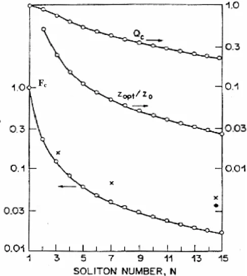
Numerical techniques have been used to obtain the compression factor Fc and
the optimum fiber length zopt as a function of N [2.6]. The inverse scattering
method can also be used to obtain these quantities for integer values of N. Figure 2.5 shows the variation of Fc-1 and zopt/z0 with N for values of N from 1 to 15.
Also shown is the quality factor Qc, defined as the fraction of input pulse energy
appearing in the compressed pulse. In contrast to the case of a grating-fiber compressor, Qc is significantly smaller than its ideal value of unity and decreases
monotonically as N increase. This drawback is inherent in all soliton-effect compressors. The remaining pulse energy appears in the form of a broad pedestal around the compressed pulse. The physical origin of the pedestal can be understood as follows. During the initial narrowing stage, the evolution of higher-order solitons is dominated by SPM. Since the SPM-induced chirp is linear only over the central part of the pulse, only the central part is compressed by anomalous GVD. Energy in the pulse wings remains uncompressed and appears as a broad pedestal.
Numerical simulations performed for values of N up to 50 show that the compression factor Fc and the optimum fiber length of a soliton-effect compressor
are well approximated by the empirical relations [2.7]
N
2 0 1 . 1 32 . 0 N N z zopt + ≈ , (2.2.11) These relations are accurate to within a few percent for N>10 and can serve as simple design rules. The results of Fig. 2.4 assume an unchirped input pulse with “sech” shape. Much higher compression factors are possible for chirped input pulses having specific pulse shapes [2.8].
2.2-4 Intrapulse Raman Scattering
Intrapulse Raman scattering plays the most important role among the higher-order nonlinear effects. The need to include this term became apparent when a new phenomenon, called the soliton self-frequency shift (SSFS), was observed in 1986 [2.9] and explained using the delayed nature of the Raman response [2.10], the Raman-induced frequency shift can be written in real units as
) 15 /( 8 ) ( 4 0 2T z T z R R β ω =− Δ , (2.2-12) The negative sign shows that the carrier frequency is reduced, i.e., the soliton spectrum shifts toward longer wavelengths or the “red” side.
Physically, the red shift can be understood in terms of stimulated Raman scattering. For pulse widths ~1 ps or shorter, the spectral width of the pulse is large enough that the Raman gain can amplify the low-frequency (red) spectral components of the pulse, with high-frequency (blue) components of the same pulse acting as a pump. The process continues along the fiber, and the energy from blue components is continuously transferred to red components. Such an energy transfer appears as a red shift of the soliton spectrum, with shift increasing with distance. As seen from Eq. (2.2-12) the frequency shift increases linearly along the fiber. More importantly, it scales with the pulse width a T0-4, indicating that it
can become quite large for short pulses.
2.3 References
[2.1] R. H. Stolen, J. Botineau, and A. Ashkin, “Intensity discrimination of optical pulses with birefringent filters”, Opt. Lett. 7, 512 (1982).
[2.2] M. Hofer, M. E. Fermann, F. Haberl, M .H. Ober and A. J. Schmidt, “Mode locking with cross-phase and self-phase modulation”, Opt. Lett. 16, 502 (1991). [2.3] H. A. Haus, J. G.. Jujimoto, E. P. Ippen, “Analytic theory of additive pulse and
Kerr lens mode locking”, IEEE J. Quant. Electron. QE-28, 2086 (1992). [2.4] G. P. Agrawal, Nonlinear Fiber Optics (Academic press, San Diego, 2001).
[2.5] F. Shimizu, “Frequency Broadening in Liquids by a Short Light Pulse”, Phys. Rev.
Lett. 19, 1097 (1967).
[2.6] L. F. Mollenauer, R. H. Stolen, J. P. Gordon and W. J. Tomlinson, “Extreme picosecond pulse narrowing by means of soliton effect in single-mode optical fibers”, Opt. Lett. 8, 289 (1983).
[2.7] E. M. Dianov, Z. S. Nikonova, A. M. Prokhorov and V. N. Serkin, “Optimal compression of multisoliton pulses,” Sov. Tech. Phys. Lett. 12, 311(1986).
[2.8] N. N. Akhmediev and N. V. Mitzkevich, “Extremely high degree of N-soliton pulse compression in an optical fiber”, IEEE J. Quantum Electron. 27, 849 (1991).
[2.9] E. M. Mitschke and L. F. Mollenauer, “Discovery of the soliton self-frequency shift”, Opt. Lett. 11, 659 (1986).
[2.10] J. P. Gordon, “Theory of the soliton self-frequency shift”, Opt. Lett. 11, 662 (1986).
Fig. 2-1 Structure of nonlinear polarization rotation
Com pres s Broade n Broad en Com pres s
Fig. 2-3 Structure of stretch-pulse laser
Fig. 2-4 Temporal variation of the phase shift φNL and the frequency chirp δω induced by SPM
Fig. 2-4 Variation of compression factor Fc, optimum fiber length zopt, and quality factor Qc with
the parameter N. Data points correspond to experiments performed with 320-m (crosses) and 100-m (solid dots) fober. (After Ref [2.7])
Chapter 3
Dual-stage soliton compression of a self-started
additive pulse mode-locked erbium-doped fiber
laser for 48 fs pulse generation
3.1 Introduction
Ultrashort pulsed fiber laser sources have found versatile applications in fields of telecommunication networks, ultrafast optical diagnosis, and optomechanic micro-fabrication, etc. Recently, femtosecond rare-earth doped fiber lasers have emerged rapidly from versatile mode-locking technologies such as the kerr-type mode-locker [3.1, 3.2], semiconductor saturable absorbers [3.3, 3.4], self-started additive (or stretched) pulse mode-locking (APM or SPM) via nonlinear polarization rotation [3.5, 3.6], dispersion-managed active mode-locking using electro-optic or electroabsorption modulators [3.7, 3.8], and optical injection mode-locking with semiconductor optical amplifiers [3.9, 3.10]. Tamura et al. reported a remarkable erbium-doped fiber laser (EDFL) scheme that uses a simple nonlinear polarization rotation controlled APM or SPM technique to generate a 77 fs pulse width under intracavity dispersion compensation and soliton-effect compression [3.5, 3.6]. Fiber-based soliton-effect compression is a promising technique for externally shortening pulse width [3.11], however, it relies strictly on the control of soliton order as well as the peak power of the compressed pulses. To data, the highest energy ever obtained from the short-cavity APM-EDFL system with <100 fs pulse width of which we are aware is 0.78 nJ. In that case a stretched pulse amplification and compression
were employed to keep the pulse energy from spreading to the pulse pedestals during the high-order soliton compression process8. High-order soliton-effect compression inevitably leads to poor confinement of pulse energy, as the high-peak-power pulse also induces significant soliton self-frequency shift (SSFS) effect [3.12] that roughly enhances Raman effect by the inverse fourth power of the pulse width. The soliton compression eventually deforms the high-order soliton into a sharp principle peak with a pedestal broadened both in time and the spectral domain [3.13, 3.14]. The SSFS effect must be greatly suppressed to enlarge the pulse compressing ratio without dissipating the principle pulse energy into pedestals.
In this letter, we combine the self-started APM with a dual-stage soliton pulse-compression technique to make possible 48-fs pulse generation from a simplified ring-configured EDFL. The shortening of the APM-EDFL pulse relies mainly on second-order soliton compression in a 50 cm long standard single-mode fiber (SMF) at the first stage and third-order soliton compression in a 45 cm long large-effective-area fiber (LEAF) at the second stage. The proposed dual-stage compression architecture benefits from the effective pedestal suppression as opposed to what happens with conventional single-stage high-order soliton compressing.
.
3.2 Experimental Setup
The experimental setup for the self-started APM EDFL and the dual-stage all-fiber based soliton compressor is illustrated Fig. 3.1. The total cavity length of the EDFL is about 4.98 m, which consists of a 980 nm/ 1550 nm wavelength division multiplexing coupler for launching the 980 nm pumping laser diode into the EDFL cavity, a polarized isolator sandwiched by two polarization controllers, a 90/10 output coupler and a 1.07m-long erbium-doped fiber with a net positive dispersion of +0.107±0.011 ps2.
The dispersion of the isolator was dominated by the 5.4-mm yttrium iron garnet crystal and estimated to be +0.003 ps2. The rest of EDFL cavity was constructed from 3.91 m standard single-mode fiber that has a dispersion of -0.022 ps2/m. The net negative dispersion was -0.086 ps2, and the total dispersion was estimated to be +0.024±0.011 ps2.
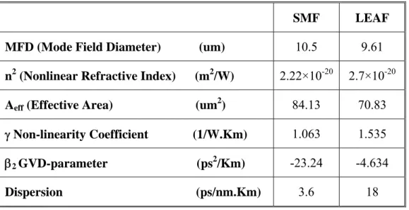
After detuning of the polarization controller, the stretched-pulse APM of the EDFL was initiated, which yields a Gaussian-like pulse shape of >300-fs duration, 16.6-nm linewidth, and 40-MHz repetition frequency. The central wavelength was 1560 nm and the average power was 0.96 mW, corresponding to pulse energy of 24 pJ. Self-started APM was initiated by increasing the pumping power to the mode-locked threshold of 210 mW and slightly detuning the polarization controller. After the peak power into the soliton regime was increased, the output pulse was launched into a SMF and LEAF link for dual-stage soliton compression. The dual-stage soliton compression link consisted of a 50 cm long SMF and a 45 cm long LEAF. Table 3.1 shows the optical parameters of the SMF and LEAF at 1560 nm.
3.3 Results and Discussion
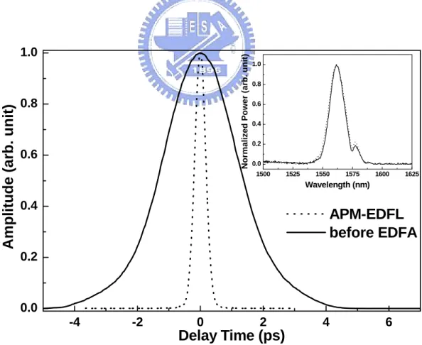
The APM-EDFL generates Gaussian-like pulses of >300-fs pulse width and 16.6-nm linewidth at a repetition frequency of 40 MHz. The autocorrelation traces and corresponding spectra of the original and dispersed pulses [before the erbium-doped fiber amplifier (EDFA)] are shown in Fig. 3.2. A segment of SMF with optimized length is inserted between the APM-EDFL and the EDF to control the prechirp of the APM-EDFL pulses before launching into the erbium-doped fiber. The pulse width is stretched to 2 ps to maintain sufficiently low peak power during the amplification process, such that the SSFS effect can be avoided. In principle, the
achievable soliton order depends on the peak power of the input pulse, as describe by N2 = LD/LNL = γP0T02/∣β2∣ [3.9], where N is the soliton order, γ is the nonlinearity
coefficient, P0 is the peak power, T0 is the half-width (at 1/e-intensity point) of the
incident sech2-like pulse with a FWHM of TFWHM~1.763T0, and β2 is the
group-velocity dispersion parameter. The pulse pattern of high-order soliton reaches a minimum pulse width periodically at an optimum fiber length zopt, as given by the
relationship of zo = πLD/2 ≅ zopt[0.32/N+1.1/N2]-1. However, the inherent drawback of
soliton-effect compression is that the pulse quality Qc (defined as the energy ratio of
the central pulse to total pulse) decreases monotonically from its ideal value of 1 as the soliton order N increases, providing a broadened pulse with a separately large and uncompressed pedestal.
3.3.1 SMF Compression
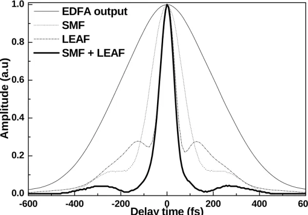
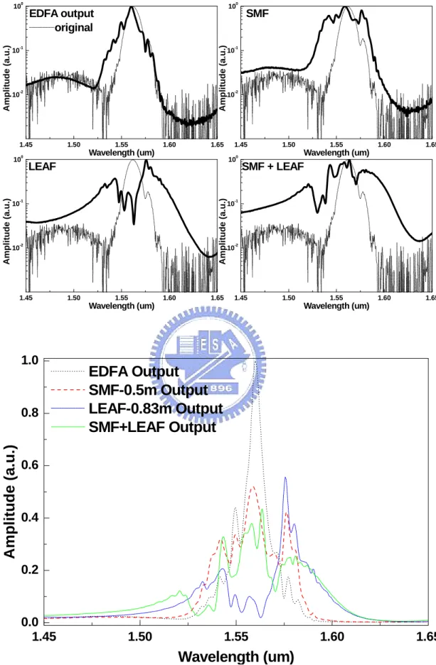
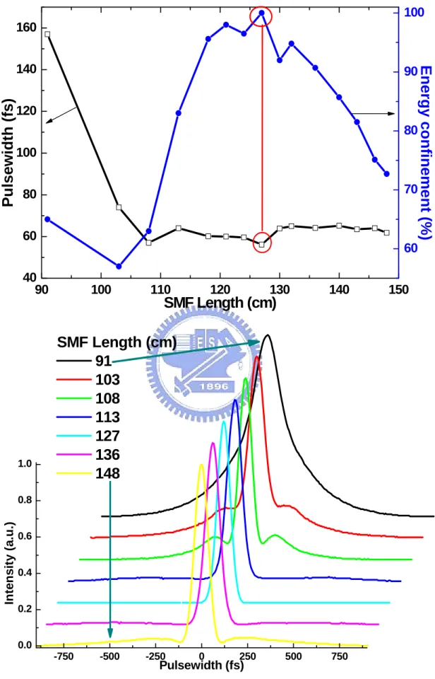
Figure 3.3 show the autocorrelated traces of the output pulses from the EDFA and different fiber compressors. First, we investigated pulse compression in a short length of standard SMF. After amplification in the second erbium-doped fiber, the prechirped APM-EDFL pulse shortens from 2 ps to 410 fs, with a spectral linewidth of 10 nm, as evaluated assuming a Gaussian shape. Figure 3.4 shows the compressed pulsewidth as a function of SMF length. Initially, the pulsewidth decreases linearly with increasing SMF and a optimized SMF length of 50 cm corresponding to a shortest compressed pulsewidth of 108 fs and associated spectral linewidth of 33.4 nm, evaluated assuming a hsec2 shape, which is in good agreement with the theoretically predicted pulsewidth for a second-order soliton. Longer SMF length inevitably leads to pulse broadening. At the first SMF-based soliton compression stage, up to 85% energy can be confined within the central portion of the compressed soliton pulse,
which corresponds to peak power of 4.13 kW.
3.3.2 LEAF Compression
Afterwards, a LEAF spool with stronger nonlinear effect due to smaller β2 than
the SMF is also employed. The single-stage LEAF based soliton compressor shows a nearly fifth-order soliton with a pulse width of 53 fs and a peak power of 4.45 kW. However, nonlinear dispersive effects should be taken into account when a short pulse is propagating with high peak power in the highly nonlinear LEAF spool. The Raman conversion is found to bedominant, which causes a continuous downshift of the mean frequency of the APM-EDFL pulse propagating in highly nonlinear LEAF spool. For an input pulse width of <1 ps, the spectral width is sufficiently wide to support the Raman gain, which pumps the red spectral components by the blue components of the same pulse. Such self-pumping-induced Raman amplification continues along the LEAF spool, causing an energy transfer from blue to red components of the APM-EDFL pulse. As shown in Fig. 3.5, the SSFS effect is concurrently enhanced at such a high soliton order, providing a greatly split and redshifted spectrum and a separated pedestal containing 55% of the total pulse energy. A 15 nm red shift is observed for the soliton pulse compressed by the LEAF. In this case, the use of a multistage dispersion arrangement is mandatory to improve the compressed pulse shape with the suppressing SSFS effect.
3.3.3 SMF+LAEF Compression
To achieve the largest compression ratio without sacrificing pulse energy confinement, we combine the SMF and LEAF to perform a dual-stage soliton
LEAF stage. In particular, the reduction in soliton order can lead to the efficient generation of a nearly pedestal-free soliton pulse shape with strictly confined pulse energy. Figure 3.6 shows the compressed pulsewidth as a function of LEAF length after the SMF length of 50cm. Initially, the pulsewidth decreases linearly with increasing LEAF and the maximum pulse width compression ratio was observed after the output of a LEAF spool with a length of 45 cm corresponding to a shortest compressed pulsewidth of 48 fs, evaluated assuming a hsec2 shape, which is in good agreement with the theoretically predicted pulsewidth for a dual-stage soliton compression. Longer SMF length inevitably leads to pulse broadening. A dual-stage soliton compression with peak power of 8.85 kW and a pulse width of 48 fs is achieved at the SMF-LEAF link, while the pedestal energy is <15% of the total pulse energy. The lasing spectrum of the soliton compressed EDFL pulse greatly extends from 1475 to 1625nm with a slightly modulated envelope (see Fig. 3.5). Such a wide energy-redistributed spectrum reveals an enhanced SSFS phenomenon that is due to both self-phase modulation and intrapulse stimulated Raman scattering [3.11].
Previously, Chernikov et al. [3.15] demonstrated soliton compression of pedestal-free EDFL pulses to 50 fs by use of dispersion-decreasing fiber in a less-integrated system with a pulse-width compression ratio of <3. They further implemented a directly soliton-compressed EDFL set with a pedestal-free but broadened pulse width of 115 fs under a pulse-width compression ratio of 5 [3.16]. A higher pulsewidth compression ratio of 25 was achieved in a more complicated system with four steps like dispersion decreasing stages [3.17], which generates soliton compressed 20 fs pulse with a resident pedestal. Our simplified all-in-one scheme is thus competitive with these feature works for generating pedestal-free sub- 50 fs pulses with a relatively high compression ratio.
3.4 Conclusion
In conclusion, a 48-fs pulse has been generated from a self-started additive pulse mode-locked Erbium-doped fiber laser by using a SMF and LEAF based dual-stage nonlinear fiber compressor. Although the single LEAF stage effectively compresses the APM-EDFL pulse to 53 fs, it inevitably induces a soliton self-frequency shift effect due to such a high peak power of pulses. The pulse spectrum is red-shifted by 15 nm compared with the original or the SMF compressed spectra. The proposed dual-stage SMF+LEAF compressor link benefits from a large sevenfold pulse width compression ratio, optimized pulse energy confinement of >85%, and a reduced SSFS compared with conventional approaches. With the proposed link, the SSFS and pedestal effects induced by high-power soliton compression can be greatly suppressed in the APM-EDFL soliton pulse.
3.5 References
[3.1] M. E. Fermann, L. M. Yang, M. L. Stock, and M. J. Andrejco, “Environmentally stable Kerr-type mode-locked erbium fiber laser producing 360-fs pulses,” Opt.
Lett. 19, 43 (1994).
[3.2] K. Tamura, J. Jacobson, E. P. Ippen, H. A. Haus, and J. G. Fujimoto, “Unidirectional ring resonators for self-starting passively mode-locked lasers,”
Opt. Lett. 18, 220 (1993).
[3.3] B. C. Barnett, L. Rahman, M. N. Islam, Y. C. Chen, P. Bhattacharya, W. Riha, K. V. Reddy, A. T. Howe, K. A. Stair, H. Iwamura, S. R. Friberg, and T. Mukai, “High-power erbium-doped fiber laser mode locked by a semiconductor saturable absorber,” Opt. Lett. 20, 471 (1995).
and Y. Hu, “Nonlinearly limited saturable-absorber mode locking of an erbium f iber laser,” Opt. Lett. 24, 1074 (1999).
[3.5] K. Tamura, E. P. Ippen, H. A. Haus, and L. E. Nelson, “77-fs pulse generation from a stretched-pulse mode-locked all-fiber ring laser,” Opt. Lett. 18, 1080 (1993).
[3.6] K. Tamura, C. R. Doerr, L. E. Nelson, H. A. Haus, and E. P. Ippen, “Technique for obtaining high-energy ultrashort pulses from an additive-pulse mode-locked erbium-doped fiber ring laser,” Opt. Lett. 19, 46 (1994).
[3.7] W. W. Hsiang , C. Y. Lin , M. F. Tien, and Y. C. Lai, “Direct generation of a 10 GHz 816 fs pulse train from an erbium-fiber soliton laser with asynchronous phase modulation,” Opt. Lett. 30, 2493 (2005).
[3.8] M. Nakazawa and E Yoshida, “A 40-GHz 850-fs regeneratively FM mode-locked polarization-maintaining erbium fiber ring laser,” IEEE Photon.
Technol. Lett. 12, 1613 (2000).
[3.9] G.-R. Lin, Y.-S. Liao, and G.-Q. Xia, “Dynamics of optical backward-injection-induced gain-depletion modulation and mode locking in semiconductor optical amplifier fiber lasers,” Opt. Express 12, 2017 (2004). [3.10] G.-R. Lin and I.-H. Chiu, “Femtosecond wavelength tunable semiconductor
optical amplifier fiber laser mode-locked by backward dark-optical-comb injection at 10 GHz,” Opt. Express 13, 8772 (2005).
[3.11] G. P. Agrawal, Nonlinear Fiber Optics (Academic press, San Diego, 2001)
[3.12] J. P. Gordon, “Theory of the soliton self-frequency shift,” Opt. Lett. 11, 662 (1986).
[3.13] M. Miyamoto, M. Tsuchiya, H. F. Liu, and T. Kamiya, “Generation of Ultrashort (~65fs) Pulses from 1.55 µ m Gain-Switched Distributed Feedback (DFB) Laser
with Soliton Compression by Dispersion Arrangements,” Jpn. J. Appl. Phys. 35, L1330 (1996).
[3.14] P. Beaud, W. Hodel, B. Zysset, and H. P. Weber, “Ultrashort pulse propagation, pulse breakup, and fundamental soliton formation in a single-mode optical fiber,” IEEE J. Quantum Electron. QE-23, 1938 (1987)
[3.15] S.V. Chernikov and P.V. Mamyshev, “Femtosecond soliton propagation in fibers with slowly decreasing dispersion,” J. Opt. Soc. Am. B 8, 1633 (1991).
[3.16] S.V. Chernikov, E. M. Dianov, D. J. Richardson, and D. N. Payne, “Soliton pulse compression in dispersion-decreasing fiber,” Opt. Lett. 18, 476 (1993)
[3.17] Koji Igarashi, Masato Kishi and Masahiro Tsuchiya, “Higher-Order Soliton Compression of Optical Pulses from 5 ps to 20 fs by a 15.1-m-long Single-Stage Step-like Dispersion Profiled Fiber ,” Jpn. J. Appl. Phys. 40, 6426 (2001).
Fig. 3.1 Experimental setup of the APM-EDFL system with an externally dual-stage soliton compressor. -4 -2 0 2 4 6 0.0 0.2 0.4 0.6 0.8 1.0
APM-EDFL
before EDFA
A
m
plitude
(a
rb. unit)
Delay Time (ps)
1500 1525 1550 1575 1600 1625 0.0 0.2 0.4 0.6 0.8 1.0 Nor m alize d P o w e r ( a rb . u nit ) Wavelength (nm)Fig. 3.2 Auto-correlated pulse traces and corresponding spectra (inset) of the original and EDFA amplified pulses.
-600 -400 -200 0 200 400 600 0.0 0.2 0.4 0.6 0.8 1.0
Am
plitude
(a
.u)
Delay time (fs)
EDFA output
SMF
LEAF
SMF + LEAF
Fig. 3.3 Auto-correlation traces of the APM-EDFL pulse after the EDFA, the SMF, the LEAF, and the SMF+LEAF link. 0 50 100 150 200 0 50 100 150 200 250 300 350
FWHM of
hsec2-type pul
ses (
fs)
Length (cm)
Length of the Different SMF
1.45 1.50 1.55 1.60 1.65 10-2 10-1 100 original Amplit ude (a.u.) Wavelength (um) EDFA output 1.45 1.50 1.55 1.60 1.65 10-2 10-1 100 Amplit ude (a.u.) Wavelength (um) SMF 1.45 1.50 1.55 1.60 1.65 10-2 10-1 100 Amplitud e (a.u.) Wavelength (um) LEAF 1.45 1.50 1.55 1.60 1.65 10-2 10-1 100 Amplitud e (a.u.) Wavelength (um) SMF + LEAF 1.45 1.50 1.55 1.60 1.65 0.0 0.2 0.4 0.6 0.8 1.0
EDFA Output
SMF-0.5m Output
LEAF-0.83m Output
SMF+LEAF Output
A
m
pl
it
ude (a.
u
.)
Wavelength (um)
Fig. 3.5 Normalized spectra of the APM-EDFL pulse after the EDFA, the SMF, the LEAF, and the SMF+LEAF link.
0 5 10 15 20 25 30 35 40 45 50 55 60 65 40 50 60 70 80 90 100 110 120
FWHM of hse
c
2
-ty
pe
puls
e
(fs
)
LEAF Length (cm)
Fig. 3.6 The compressed pulsewidth as a function of LEAF length
Table 3.1 The optical parameters of the SMF and LEAF at 1560nm
SMF LEAF MFD (Mode Field Diameter) (um) 10.5 9.61 n2 (Nonlinear Refractive Index) (m2/W) 2.22×10⁻²⁰ 2.7×10⁻²⁰ Aeff (Effective Area) (um2) 84.13 70.83
γ Non-linearity Coefficient (1/W.Km) 1.063 1.535
β2 GVD-parameter (ps2/Km) -23.24 -4.634
Chapter 4
56-fs High-Power Pedestal-Free
Gaussian-Shape Pulse Compression with a
Pre-Chirped Large-Mode-Area Er-Doped Fiber
Amplifier
4.1 Introduction
Passively mode-locked Erbium-doped fiber lasers (EDFL) are dependable source for generating sub-100fs pulses at 1550nm, however, such EDFLs typically generate pulses with energy lower than those of solid-state lasers (such as Ti:sapphire laser). Owing to the inherent fiber nonlinearity, the EDFL usually meet difficulty in obtaining multi-nJ pulses. To increase the peak power, the multi-mode fibers were employed suppressing the nonlinear effect, and compression of chirped pulses with bulk-optic components after the EDFL is frequently performed [4.1]. Alternatively, the chirped pulse amplification (CPA) technique were particular designed to stretch ultrashort pulses prior to amplification and to recompress them back after the amplification is completed, with all three types of dispersive elements [4.2-4.4]. A vintage configuration which employed a fiber based pulses stretcher in an EDFA, and a pair of bulk diffraction gratings as the compressor after the EDFA was reported to achieve 420-fs pulses with energy of 3 nJ after the grating pair. Nonetheless, such a bulky diffraction grating compressor makes the whsle fs laser system un-compact, which also degrades the pulse quality as each frequency component passes a different optical path. Subsequently, fiber Bragg gratings were inserted after the EDFA to stretch and
compress the pulsewidths to 408fs [4.3] and 900 fs [4.4] associated with energies of 3 and 1.6 nJ, respectively. The all-fiber configuration although is alignment-free, which still limits the achievable peak powers due to the fiber nonlinearity. Recently, a photonic bandgap fiber (PBF) based compressor, has been introduced into the CPA system, [4.5, 4.6] however, such special structural fibers are difficult to splice with standard optical fibers for high coupling efficiency. In particular, the extremely large GVD of the PBF leads to a strict tolerance on the optimized length, while the large dispersion slope of the PBF also makes the nonlinear chirp hard to be compensated completely. These constrain the peak power of compressed pulses at few kW. More recently, a highly doped EDF [4.7, 4.8] was employed, to shorten length of the EDF and to reduce the high-order nonlinear effect during pulse amplification and compression processes in EDFA and single mode fiber (SMF) based soliton compressor, respectively. To date, the ultrashort pulsewidths of 34 fs [4.7] and 43 fs [4.8] were obtained with peak power of 140 and 43 kW, respectively, at the cost of low confinement ratio of the pulses energy 55% and 39% remaining in central peaks observed in cited references. The pulse pedestal remains uncompressed.
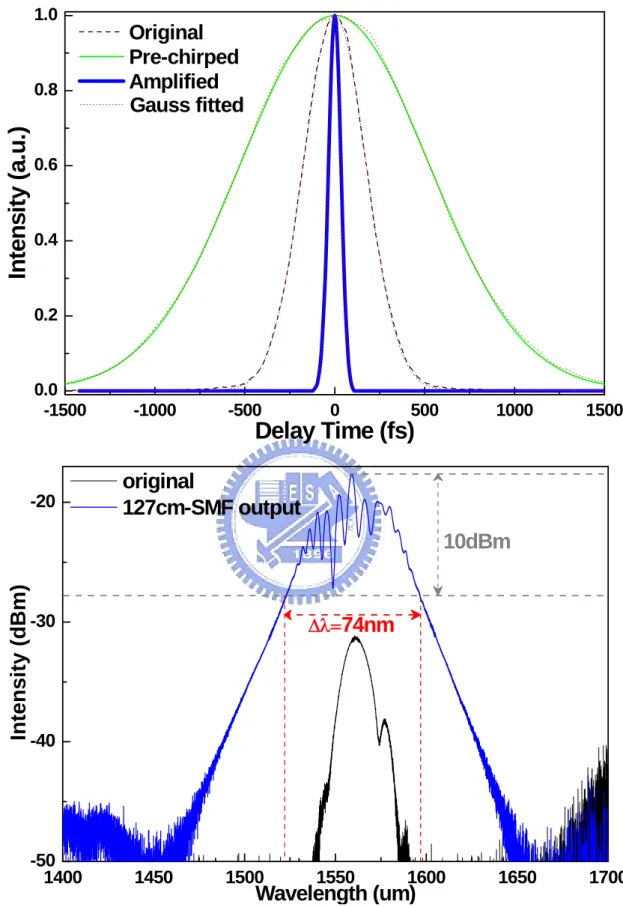
In this work, we demonstrate a novel large-mode-field-area (LMFA) highly Er-doped fiber based EDFA for concurrently pre-chirping, amplifying, and compressing 300-fs passively mode-locked EDFL pulses, which results in the generation of high-power and pedestal-free, ultrashort Gaussian pulse with its extremely broadened linewidth up to 150 nm (within 10-dB decay). To prevent the unexpected nonlinearly stimulated Raman scattering effect induced during the high-power amplification process, our concept is using such a simplified EDFA based all-fiber compressor with a very short but highly doped LMFA Er-doped fiber for minimizing the nonlinear process during the amplification of EDFL pulses, and using a
pre-chirped SMF segment for controlling the chirp of pulse before launching into the Er-doped fiber and the last compression stage. With the fine adjustment on both the lengths of the SMF segments for per-chirping and soliton compressing within the LMFA-EDFA, we primarily report the optimized condition for obtaining the shortest pulsewidth, the highest peak power and the optimum energy confinement of the self-started nonlinear-polarization-rotation mode-locked EDFL pulses after an amplified compression in the LMFA-EDFA.
4.2 Design and Implementation of EDFL and
LMFA-EDFA
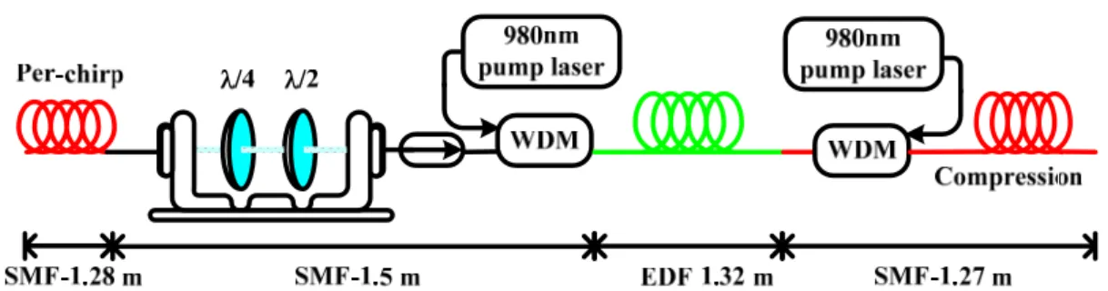
The experimental setup for the generation of high-power pedestal-free femtosecond pulse is configured by a passively mode-locked EDFL system and a specially designed LMFA-EDFA with pre-chirping function for input pulses. The passively mode-locked EDFL illustrated in Fig. 4.1 is ring cavity design, which consists of a single laser diode at 980 nm as the pumping source launched via a 980/1550nm single-mode-fiber (SMF) based wavelength division multiplexing coupler, a segment of Er-doped fiber with length of only 1.08 m as the gain medium, a polarized isolator sandwiched by two sets of polarization controllers as the passive mode-locker, and a SMF based 1×2 coupler with 10% coupling ratio as the output port.
The total SMF length in the EDFL ring cavity is 3.9 m, which leads to a total dispersion of about +0.024±0.011 ps2. The mode-locking of EDFL is self-started by using nonlinear polarization rotation at a threshold pumping power of only 210 mW. In Fig. 4.2, we schematically show a highly-doped LMFA Er-doped fiber based EDFA
mode-locked EDFL pulses simultaneously. The LMFA-EDFA consists of a 1.28m-long SMF segment as a pulse pre-chirper, a polarization controller (PC) was inserted between the EDFL output port and the pre-chirped SMF segment to improve the polarization quality of input EDFL pulse, a forward 980/1550nm pumping wavelength-division-multiplexing (WDM) coupler, a LMFA Er-doped fiber as the gain medium and a backward pumping WDM coupler. The peak absorption, the mode-field diameter, and length of the EDF are 80±8 dB/m, 9.5±0.8 um, and 1.32 m, respectively. The SMF lengths before and behind the LMFA Er-doped fiber are 2.78 m and 1.27 m, respectively. Table 4.1 shows some impartment parameters of the single mode very highly Er-doped fiber.
In experiment, two high-power laser diodes at wavelength of 980 nm are employed to bi-directionally pump the LMFA-EDFA through two WDM couplers directly spliced to both ends of the Er-doped fiber. The maximum launching power of the forward and backward pumping lasers are 140 mW and 120 mW, respectively. The LMFA-EDFA exhibits a small-signal gain of 20 dB and a maximum average output power of 104 mW. Afterwards, the EDFL pulse is launched into the LMFA-EDFA for raising its peak power into the soliton regime. The WDM coupler spliced at the output port of the LMFA-EDFA compensates the chirping of amplified EDFA pulse with its anomalous dispersion property, and the amplified EDFL pulse concurrently experiences a low-order soliton-effect compression at this stage. In stead of the LMFA Er-doped fiber, all of the other fiber components are made by SMF-28 with a dispersion parameter β2 of -21.4 ps2/km.