1058 IEEE TRANSACTIONS ON MAGNETICS, VOL. 41, NO. 2, FEBRUARY 2005
Design of Optical Head With Holographic Optical
Element for Small Form Factor Drive Systems
Hsi-Fu Shih, Chi-Lone Chang, Kuei-Jen Lee, and Chi-Shen Chang
Abstract—An optical head composed of an optical module and a biaxial actuator is designed for small form factor drives. This system adopts a finite-conjugate objective lens with numerical aperture 0.65 for 654-nm wavelength. A holographic optical element is used for simplifying the optical configuration which provides a better approach for alignment. The actuator is of a spider-like suspension for the focusing and is of a swing arm for the tracking.
Index Terms—Actuator, holographic optical element (HOE), op-tical pickup head, small form factor.
I. INTRODUCTION
I
N recent years, the growing market for digital music players, still cameras, personal digital assistants, mobile communi-cations, etc., has enhanced the optical drive with small form factor to be developed rapidly. Several systems have been pro-posed before [1]–[4]. One of the key technologies is to achieve the requirement in light weight and small size of the optical pickup unit. Therefore, microoptical elements, like lenses and prisms, are generally used in optical head designs. Much diffi-culty regarding assembly and manufacturing needs to be over-come when dealing with a lot of discrete elements in a unit with precision and miniaturization.The holographic optical elements (HOEs) have been widely applied to optical heads with their particular features in the func-tions of splitting laser beam, generating servo signal, and cor-recting optical aberrations. The use of HOEs not only minimizes the number of components for a compact structure but also sim-plifies the light path. In this paper, we describe an optical con-figuration with an HOE for the small form factor pickup head. With this design, the head dimension, component cost, and fab-rication complexity could be effectively reduced. Also, by ap-plying the virtual image method [5] to the machine vision, the alignment of the optical unit is easy and the manufacturing fea-sibility could be possibly achieved. Besides, we are proposing a
Manuscript received August 31, 2004.
H. F. Shih is with the Mechanical Engineering Department, National ChungHsing University, Taichung, 402 Taiwan, R.O.C. (e-mail: hfshih@ nchu.edu.tw).
C. L. Chang is with the Opto-Electronics and Systems Laboratories, In-dustrial Technology Research Institute, Hsinchu 310, Taiwan, R.O.C. (e-mail: [email protected]).
K. J. Lee is with the Electrical Engineering Department, YuanZe University, Taoyuan 320, Taiwan, R.O.C. (e-mail: [email protected]).
C. S. Chang is with the Opto-Electronics and Systems Laboratories, Indus-trial Technology Research Institute, and the Mechanical Engineering Depart-ment, National ChiaoTung University, Hsinchu 310, Taiwan, R.O.C. (e-mail: [email protected]).
Digital Object Identifier 10.1109/TMAG.2004.842021
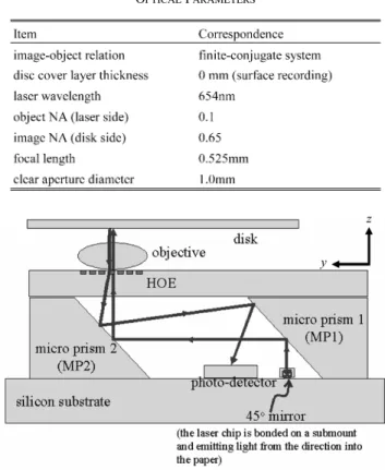
TABLE I OPTICALPARAMETERS
Fig. 1. Schematic diagram of the optical configuration.
novel biaxial actuator design consisting of a spider-like suspen-sion for the focusing and a swing arm with a voice coil motor for the tracking.
II. SYSTEMDESCRIPTION ANDANALYSIS
The optical configuration based on the parameters in Table I was designed. We adopted a finite-conjugate objective lens with numerical aperture (NA) 0.65 for 654-nm wavelength in the system. Fig. 1 shows the schematic diagram of the optics. An edge-emitting laser chip is bonded on a silicon substrate with a 45 etching micromirror. It reflects the laser beam upward to a 45 microprism (i.e., MP1) which is upside-down bonded on the substrate. After reflected by MP1, the beam is redirected by the other 45 prism (i.e., MP2) to vertically enter the HOE. The zeroth-order light that passes through the HOE is focused on the disk by the objective lens. On the returning path, the beam is diffracted by the HOE, reflected by the MP1 and MP2, and fi-nally projected onto the photodetector. The MP1 and MP2 act as not only reflectors but also two spacers for supporting the HOE
SHIH et al.: DESIGN OF OPTICAL HEAD WITH HOLOGRAPHIC OPTICAL ELEMENT FOR SMALL FORM FACTOR DRIVE SYSTEMS 1059
Fig. 2. Three-dimensional layout of the optical module.
Fig. 3. Simulated focusing error signal (S-curve).
Fig. 4. Swing arm actuator design.
and objective lens. The astigmatic detection is used for gen-erating the focusing error signal (FES) from the HOE diffrac-tion. Fig. 2 presents the three-dimensional layout of the optical module. Simulation results in a symmetric S-curve as shown in Fig. 3.
The optical module was combined with a swing arm actu-ator as shown in Fig. 4. The spider-like feet were designed both as the suspension and the conduction wires for the focusing. Finite-element harmonic analysis was used to predict the vibra-tion characteristics of the focusing. The frequency response plot is shown in Fig. 5. It is worthwhile to point out that the natural frequency is approaching 100 Hz and the second resonant fre-quency is higher than 20 kHz. There is good linearity between the first and second resonance. The bandwidth results from max-imizing the structural stiffness and minmax-imizing material mass of the system. It also gives an efficient transmission of the force to the moving part. The DC and Acc sensitivity for the focusing are 1.0 mm/V and 12.2 G/V, respectively.
Fig. 5. Simulated response characteristics of the actuator for the focusing.
The HOE pattern can be designed by the binary optics tech-nology and has the wavefront represented by
(1) Usually, we take six terms of the phase polynomial as
(2) where the provides the diffraction angle in the
-direc-tion, the serve as the combination of a
focusing lens and a cylindrical lens that converges the beam and generates the astigmatism, and the remaining terms are used for correcting the coma, spherical, and high-order aberrations. The slight misalignment of the laser, photodetector, or microprism can be compensated by adjusting the HOE position. For ex-ample, shifting the HOE a distance in the negative -axis will give the phase as
1060 IEEE TRANSACTIONS ON MAGNETICS, VOL. 41, NO. 2, FEBRUARY 2005
Fig. 6. Virtual image method for the optical unit alignment.
where the astigmatic term remains unchanged and the variation of terms corresponds to the position change of the returning spot in the -, -, and -directions, respectively.
With the advantage of using HOEs, a passive alignment pro-cedure can be utilized for adjusting the relative placement of the photodetector and HOE. The conceptual drawing is shown in Fig. 6. The virtual image of the laser is obtained by backward extending the diffracted beam to the virtual focal point. This point must be coincided with the location of the photodetector image.
III. EXPERIMENTALRESULTS
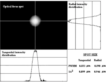
The optical components were fabricated and the optical module was assembled. The HOE pattern was etched on a glass substrate by standard lithography processes. The HOE etching depth was optimized to be around 350 nm for the fused-silica substrate. Because of no beamsplitters in our pickup design, the power efficiency of the forward path is enough for the one-speed data recording on the disc. It was calculated to be higher than 8%. A specific apparatus with a tilted microscope was constructed for the adjustment of the HOE. The HOE was aligned in order to move the laser virtual image exactly on the center of the quadrant detector. Fig. 7 shows the observed virtual image consisting of the pattern of the quadrant detector and the shape of the astigmatic returning spot, whereas the simulated spot is there for comparison. The quadrant detector was used not only for the astigmatic focusing detection but also for the push–pull tracking detection. We took the finite-conju-gate objective lens which was made by a company in the U.S. according to the optical parameters described in Table I for our experiments. With the objective lens attached, the focus spot on the disc was measured as in Fig. 8. Although the full-width at half-maximum (FWHM) spot size in the disc radial direc-tion is bigger than that in the tangential, they stay within the acceptable range when the disc specification of data pits is the
Fig. 7. Astigmatic returning spot on the quadrant detector.
Fig. 8. Measurement of the optical focus spot on the disc.
same as DVD. The spot intensity is normally distributed and no severe aberration appears.
IV. CONCLUSION
A pickup design for small form factor optical drives has been presented. By using an HOE, the optical configuration is effi-ciently simplified and the number of components is significantly reduced. The novel focusing actuator with a spider-like suspen-sion has good performance. The virtual image method provides a reliable way for alignment and is promising for manufacturing with the aid of machine vision. The simulated and experimental results are satisfactory and show that the design concept is fea-sible. An embodied system will be implemented hereafter. Fur-thermore, we hope that this construction can be applied to a high density blue-ray storage system of small form factor in the im-mediate future.
REFERENCES
[1] B. W. Bell Jr., “Dataplay’s mobile recording technology,” in Tech. Dig.
Optical Data Storage 2001, Apr. 2001, pp. 4–6.
[2] S. Kim et al., “PCMCIA like ultra small form factor optical drive,” in
Tech. Dig. Optical Data Storage 2003, May 2003, pp. 5–7.
[3] J. Lee et al., “Design and analysis of small swing arm type optical pickup for small form factor optical drive,” in Tech. Dig. Optical Data Storage
2004, Apr. 2004, pp. 147–149.
[4] I. H. Choi et al., “Miniature optical drives for mobile application,” in
Tech. Dig. Optical Data Storage 2004, Apr. 2004, pp. 201–203.
[5] W. H. Lee, “Diffractive optics for data storage,” in Proc. SPIE, vol. 2383, 1995, pp. 390–395.