tiwe
s0idioag-mode
torque
~ooauroo
off
a
PM
C:H. Fang, C.-M. Huang and S.-K. Lin
Abstract: An adaptive sliding-mode torque control system, which incorporates the merits of both the sliding-mode control and the adaptive algorithm, is proposed. Thc sliding-mode controller is constructed by two integral surhce functions. The uncertainty is formulated a s a random variable around a constant mean, so that an adaptive mechanism is used to estimate thc constant mean and the bound of the random variable. Moreover, an application of the proposed torque control to the position control of a
motor
is also presented. Some experiments verify the control theory and demonstrate the usefulness of the proposed control schemc.1 Introduction
Permanent magnetic synchronous motors (PMSM) are receiving incrcascd attention for drive applications ranging from high-perfomxuice servo drives to line-start applica- tions such as fans and pumps. The main reasous are their high power density. large torque to inertia ratio. high efficiency: and the falliug prices of high-energy magnets [I].
The main earlier methods for PMSM coiitrol are based on current control techniques. e.g., vcctor control [2]; predictive control [3]; and others [4-6]. The torque in PMSMs is usually controlled by controlling the armature current based on the fact that electromagnetic torque is proportional to the armature current. For high perfor- mance, the current coutrol is nonnally executed in the rotor &-reference frame which rotates with the rotor. Therefore, coordinate transformation is involved. The torque response under this type of control is limited by the time constant of motor winds
[q.
Rotor field-oriented (RFO) control for PMSM [j, 61 drives provides the decoupling control between the torque and flux components, :1nd can achieve good performance characteristics similar to that of a DC motor. so RFO control is a popular control method for PMSM. The drawback of the RFO is that it uses a linear PI controller to
handle the nonlinear system. Thanks to the high gain, the RFO performs well in most cases. But in worse cases (e.g.. at i t moderately high speed), the perfommice of RFO could be improved by using nonlinear control. According to the frequency response theory of linear systems, the PI controller will have a lag phenomenon in the sinusoid response for an appropriate frequency, even if the controlled plant is a first-order liiiear systeni.
The currcut trend is then to develop a nonlinear controller for a PMSM, especially using torque control laws [7-91. Direct torquc control (DTC) is one method of increasing interest in recent years. The basic principle of
DTC is to directly select the stator voltage vector according to the differences between the recerences of torque and stator flux and chcir actual values [IO]. The advantages of DTC are a quick torque response and lesser parameter depcndence. However_ torquc ripples and high sample time are drawbacks. On the other hand, feedback linealisation control can be successfully applied to the PMSM torque control [ I I , 121. However. it requires the precise values of the system parameters.
Over the past decade_ variable stmcture control strategy using a sliding-mode hiis been the focus of much research into the control of the AC drive system [13-171. The key objective of this technique is to force the system trajectory to a specific surface. known as the sliding surface_ such that the state variables of the system are totally determined by the sliding surface. The main feature of the approach is its insensitivity lo disturbances and parameter variations.
This paper presents an adaptive sliding-mode torque control Cor a PMSM. The stator voltage command is dircctly generated from the torque and flux errors based on two intcgral sliding surface functions. As in usual sliding- mode control. the asymptotic stability of the proposed control law can be shown by the Lyaputiov method. Moreover. an adaptive inference mechanism with adapta- tion of thc nominal uncertainty and the maximum offset value is included. which follows from the concept of the adaptive sliding-mode coilti-ol [16]. Furthermore. we propose a cascade control system to apply the sliding-mode torquc control to the position control of a PMSM. The overall control system consists of the inner loop of the torque control and the outer loop of the position control. Thc position control is designed using model rcfcrcnce adaptive control (MRAC). Some experiments are provided to verify the control systcm.
2 Model of a PMSM
The model of a surface-mounted PMSM in the synchro- nous rotor-rotating reference frame (d, q) can be described as [6. 181:
where R , is the stator resistance. L, is the stator inductance, K, is thc armature (or stator) hack EMF constillit, B end J
are the friction coefficient and the moment of inertia of the motor. p is the number of pole-pairs, or is the rotor speed, (i<l>,
LIJ
and (iif15. II<J are. respectively. stator currents andvoltages in the rotor-rotating frame (d. q), and T, and Tr,
are the clcctromagnetic torque and external load torque. Note that
T, = d i ~ , s v ~ ~ T -
h,cf$
(4) where /i 3/~/2, and (qcLy>fomi of'
are the stator fluxes in the
q C i s L.\G/s
+
K,,
( 5 )( 6 )
3 Adaptive sliding-mode torque control
We want to propose a direct torque control scheme for B PMSM, which tracks the electromagnetic torque 7;. by controlling the voltage inputs to the motor. It is known that the squared norm of the stator fluxes is closely related to electromagnetic torque. We then need to take into account the active torqitc (u7) as well as the square of the flux n o m
(um). Both are defined as follows:
111 = + ( P d - halpPa ( 7 )
(8)
U 9 =
((Pi
+ (f:.$,P
( 7 ) and (8) require tlie signals of i(,,>, i<,.>- ~ p , ~ ~ , and 'per,- The currcnts i,r, and $.,,; can be mcasured. however, the <p,i. and
lpcfi5 observer can be calciikated from (5) and (6). Further-
nioi-e, let the errors he e r
=
IIe4 uCni - u9- whcre up<,, and uC.,, nr
values of the active torque and the squire of the flux n o m . Applying the sliding-mode control theoiy to the present problem, we first define tlie integral surface functions for the active torque (sl) and the square o f the flux n o m ( S I ) a s follows:
s t = e ,
+
kl q c i l - er(O-) (9)s 2 = c
+
h-7 e,@ - e,,,(O-) (10)1
-1'
where R , and k? arc positivc gain. Oncc the system states
stay stationary on the surfaces, we then have
S I = sz = S I = .j., = 0 . According to (9) and (IO), SI = 0 and 92 = 0 lead to (11) (12) d z(14pef - U T ] = -ki(uTji,f - I I ~ ] d
z
("Bwf -Q)
= -kl ( I I d m j - q )(1 I ) and (12) ensure that the system states (uT and irq) will exponentiully converge to the reference values if they are kept on the sliding surfaces s = 0. This condition can be achieved by the sliding-mode control scheme that asks the voltage input u = [u,,, uJ' to drive the state variables o f
/LE Proc-Eccin t'mo I'd 3,
the system to the sliding surface s = 0 and to keep thein there. For this purpose, we select tlie Lyapunov function candidate B S
I 2
The time derivative of Vneeds the derivatives of s. I t follows from (1). (21, (9) and (IO) that
V = --ST'S (13)
SI
=&
+
klerbl =L,R,riii
+
K,R,i,a+
I&,-+
kI(i+j - 114)-j' + j'
I - il\ gs
The above equations are derived under the ideal situation. When we consider thc uncertainties of the system parameters (e.8.. R,, L.,,
Kj)
in ( I ) and (2); then (16) can be directly modified a s(18) S = ( b + d b ]
+
( D + d D ) u= b + z + D u
where Ab and d D are the uncertainties induced by the
model uncertainties in (I) and (2)_ and
z = db
+
dDu (19)Furthermore, we can treat the uncertainty term z in (19) as
P
a noiiiiiwl offset value Z* with ii smaller varying uncertaint i.c.. z = z * +8,, where &, = dZ2]' = [rl-zi, rz-z;] . Then (18) can be rewritten as
(20) S = b + z*
+
6,+
DuUnder the assumption that z* and 6, are known aprkiri, it can be shown that sI and s2 converge to zero a s f++
a,
if the lbllowiug sliding-inode coi1troI law is applied:where p =
b ~ ,
p21r with pI l6,,1 and p z > 1dZ21 for all f. (21) exists when the inverse D-I exists for all time.However. z* and the upper bounds of 6, are actually unknown. To get around this difficulty, we can introduce the adaptive sliding-mode control law, which is stated in the foilowing proposition.
Pvopsifion 1. Consider the PMSM in (1) and (2). The overall system will asymptotically converge to u7 = and U+ = ti+ if the inverse D-l exists and the following
adaptive sliding-mode controller is applied
0,
i = S (24)
Note that p and
i
are, respectively, the estimates of p and z* .The details of proof can he found in the Appendix Section 8.
4 Position control
4.1
Model reference adaptive control
In practical applications of a PMSM. a cascade control structure is suggested: the inner loop is the above described adaptive sliding-mode torquc control. while the outer loop can be a speed o r position control. Here, we consider only the position control, since the speed control is a simple extension.
The real sysiem to be considered is a single-link mechanical system driven by a PMSM. The block diagram in Fig. I illustrates the overall system of the proposed control method, in which the torque and flux estimator are calculated by (7) and (8). Many control methods can he used for the outer loop position controller. We select the model reference adaptive control (MRAC) scheme, hecause it is one of the most popular adaptive conirol strategies and it can adapt itself to the unknown mechanical parameters. The position controller generates the torque command to the inner loop controller_ which then asks the inverter to provide the required three-phase voltages for the PMSM.
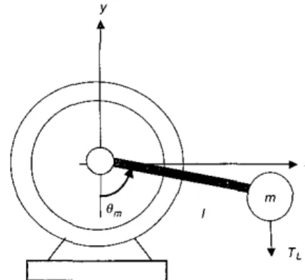
The mechanical system is a PMSM with a rod fixed on the shaft axis of the motor and is shown in Fig. 2 . The mechanical model of the system is
J i m
= - B& - nigl sin(&,,+
6'0)+
krur= - BO,, - my1 cos 0" sin 0, ( 2 5 )
- m y 1 sin Ho cos R,,,
+
k T i i 7where
0,,,
is the angular displacement of the shaft, J is the iuertia of the motor, B is the friction cocfficient, 111 is theMntmlier
-
u, UT Um vas. (PqE - b S torquelliux abc-dq~ estimator IPS transformation
t
i
Fig. 2 Meclinnicr~l sy~tem .fa motor with o rodJ.wd on rlre sli<(t
inass of the rod, I is the distance from the shaft center to the center of mass of the rod, g is the gravitational acceleration_ kr is the torque constant, and
0"
i s the null angle from the line of gravity. For the development of the MRAC, (25) isrewritten as
~ , , , = - B ~ i ) , , , - ( L b s i n O , ~ , + L , c o s O , , , ) + K J u r (26) where BJ = B/J, Ll, = liiylcosH,,/J, L, = mglsinOo/J, KJ = k&. Note that J>O.
The reference model of the MRAC is given as
where is the response of reference angular displacement for an angular displacement command r, k,, and k, are so selected that .?+k+-+k., = ( s + p l ) (s+pz) with p , , p2>0.
We first need to know the model reference control (MRC) law, which can make the overall system asynpto- tically track the reference model under the assumption that the mechanical parameters are exactly known. The MRC of the present system is
u
Fig. 1
230
with
(291
For the case when the parameters are unknown, the MRAC directly follows from MRC by applying adaptive
laws to the estimation of thc system parameters. We use the direct MRAC with unnormalized adaptive laws [19]. Since the system has the relative degree of 2; wc need the bilinear parametric model of the position error e~ Ot,,4:,, Substituting uT = C'W
+
(ur-cTw) into(29
and combining (27), we obtain (.?+kG+k,)e = K d u - cw);
which turns out to be the bilinear paratnctric model:where W,,,(s) = k,J(s+p2), p' = KJ/k,s- and W = According to Table 6.2 in
[la],
we then propose the MRAC for (30) as follows: \Vi(.?+
Pi). .'I' LIT = t'w+
t
n
(31) (32) c = -reWsign(p') ( 3 3 ) with - W =- p , n + ~ :
w(o)
=n
and the adaptive laws
where F is a diagonal matrix with positive diagonal entries. It should be remarked that the sign of p' is always known. 4.2 Experiments
The overall position control schemc in Fig. I will be verified by experiments. The experimental system is shown in Fig. 3 , which is
a
PC-based control system. A servo control card on the ISA bus of the PC provides eight A/D converters, four D/A converters, and an encoder counter. The inner loop and the outer loop controllers are implemented on the PC in C-language. The sampling time for the overall control is 0.3 ms. Thc ramp comparison modulation circuit is used to generate the PWM for driving the IGBT moduleinverter. The PMSM in the experimental system is a 4-pole, ZOO", and 92V motor with the rated current, speed, and torque of 2.2A, 3000rpn1, and OS", respectively. Thc encoder has 2000 counters per revolution. The pranieters of the motor are
R.,
= 2.148. L, = 2.4mH, andK,= 0.0738. Those of the mechanical system (see Fig. 2) are J % 0.00042 kgm2, I
=
0.1 in, and i n % 0.5 kg.time. P
a
I .o current commanu stator current
-1.01
i
0 3.5 1.0 I 5 2.0 2.5 3.0 3.5 4.0
time, s
b
Fig. 4
CI Adaptive sljdjn_e-mode torque control scheme
b RFO current control schcme
Rr,sponsm r f o sinusoidal t o q u e coimiurzd
220 AC
modulation circuit
Three experiments are conducted: 1) torque tracking control, 2) set-point position control, and ' 3 ) position
tracking control. The gains of the reference model (27) are k , = 30 and k.> = 225. The popular rotor field-oriented (RFO) control scheme is also established to a performance comparison.
In the first experiment, we consider only the inner torque control loop given as uT = 0.06 sin(1 k t ) . The experimental results for the proposed controller and the RFO are shown in Figs. 4 and 5. It is apparent that the proposed controller is superior to the conventional RFO controller for the sinusoidal torque tracking. When the motor speed is high, the temi @K,/L.,)w,- makes the motor model far from the
linearised system, so that the linear PI controller i n the RFO can no longer compensate for the large nonlinearity.
In the second experiment, the motor is asked to go to O,,,=n at
r
= Os, and then to return to H,, = ~ 1 2 at I = 2s. It should he noted that the reference active torque und is generated by the MRAC and varies before the steady-state is rcached. while the reference square flux I Q ~ < ~ is given as aconstant. The experimental results of both controllers are shown in Figs. &I I . The transient response of the proposed controlled is enlarged and shown in Figs. 12 and 13. It can be seen that the steady-state error is negligible. The history of the estimated torque shows that the values are around zero for
e,,,
= K and around about 0.5 Nm for O,,, = 4 2 ,which is consistent with the physical property. Fig. 66 shows that the parameters of the MRAC also converge to constant values, which is a property of the MRAC. It is seen from Fig. 76 that there is fluctuation in the estimated torque. This oxillation comes from the oscillation of the currents, because the estimated torque is computed using the measured currents. This oscillation does not affect the
4 0 0 1 " " ' '
"
0 0.5 1.0 1.5 2.0 2 5 3 0 3 5 4.0 lime. 5 1200 I l"e. E b Fig. 5(i Spccd of adaptive sliding-mode torque control schemc
b Speed of RFO current control scheme 232
Rc.spnse.s of u siniuoidul torque coriii?iand
0 0.5 1 0 1.5 2.0 2.5 3.0 3.5 4.0 lime. 5 -0.1 -0.2 c , , , , , time. s 0 0 5 1.0 1.5 2.0 2.5 3 0 3.5 4.0 b Fig. 6 o Position h Estimated pnrametcrs
Respon.sc.s of (I ser / l l J h l r position coininand
t,me,
*
0 time, s b Fig. 7 (I Torque command h Estimated torque5 4
:I,
, , , , , ,I
-4 -5 0 0.5 1.0 1.5 2.0 2.5 3.0 3.5 4.0 lime. I*
0 0.5 1.0 1.5 2.0 2.5 3.0 3.5 4.0 time. s b Fig. 8u Stator current (id)
h Staior current (i,)
response.^ . f a se/ point parition cunvimnd
0 10 0.09 fiux command , , , , ,
;
, 0.02 0.01 ' 0 0.5 1.0 1.5 2.0 2.5 3.0 3.5 time. s 0.10 0.09 rotor t1uxI
:::;I
0.02 0.01/ 0-, " " " 1 0 0.5 1.0 1.5 2.0 2.5 3.0 3.5 4.0 time. 5 b Fig. 9 N Command fluxb Estimated rotor flux
Responsrs of a set point pusiriorr command
command angle 2.0 reference angle actual angle -0.5 -1.0 0 0.5 1.0 1.5 2.0 2.5 3.0 3 5 4.0 lime. s -4
i
i
-61 ' ' ' I 0 0.5 1.0 1.5 2.0 2.5 3.0 3.5 4.0 time, s b Fig. 10 c"o/ scI1emr u PositioiiRe.cpunse of a se1 point comirinnd ,villi RFO current
h Stator current (13 8 6 4 2 a o -2 -4 -6 -8 0 0.5 1.0 1.5 2.0 2.5 3.0 3.5 4.0 time. s a Fig. 11 c o n t m ~ scller~le
N Canimand current (&)
Response qf a set point cornmond with RFO otri'em
4.0 command angle 2.5 2.0 n -1.0 -0.5 0
1
0 1 0.2 0.3 0.4 0.5 0 6 0 7 lime, 5 3.5 command angle 0 : : , , , , , , , , -0.5 -1.0 2.0 2.1 2.2 2.3 2.4 2.5 2.6 2 7 time, s b Fig. 12(I Position response for 0-0.75 s
h Position respoiisc for 1.95-2.75s Trunsieiit ports 0fFiq.s. 6-9
4 . 5 } -1.0
I-
I I 0 0.1 0.2 0.3 0.4 0.5 0 6 0.7 time, 5 zj-
o estimated torque -0.5 -1.0 1 2.0 2.1 2.2 2.3 2.4 2.5-
2 6 2 6 2.7 2.7 time. s b Fig. 13(I Estimated torque response for 0-0.75s
h Estimated torque response for 1.95-2.75s
234
Trunsient p r o of Figs. 6-9
output of the mechanical system, since its frequency is far from the bandwidth of the mechanical system. The comparison of Figs. 6 9 with Figs. 10 and 11 shows that the performance of both controller is equally good.
In the third experiment, a sinusoidal position command is
given as
r = ( I ~ e ~ 1 0 ' ) ~ 2 s i n ( 3 n t ) 2 (34)
which makes the starting smooth, since h ; . f ( O ) = uf(0) = H,,, = 0. The experimental results of both con- trollers are shown in Figs. 14-17. Although there is a delay between the response H,,, and the command I', the tracking ersor
O,,,
- H:, is actually negligible for the proposedcontroller, but is noticable small for the RFO. Although both controllers have almost the same performance for the position regulation, the proposed controller has good torque tracking and good position tracking, whereas the RFO has significant error in the torque tracking, so that also has some noticable errors in the position tracking.
actual angle 1 5 -0.5 -1.0 -1.5
-2.0L
-2.5 0 0.2 0.4 0.6 0 8 1.0 1.2 1.4 1.6 1.8 time, 5 0 0.2 0.4 0.6 0 8 1.0 1.2 1.4 1.6 1.8 2.0 time. s b Fig. 14sliding-riiode torque c u m o l scheirie
u Position
b Torque cominilnd and estimated torque
Responses of u ri17uroidulpositior1 romnzund with aduptice
5 Conclusions
This paper presents a new adaptive sliding-mode torque control for a PMSM. The sliding-mode controller is constructed hy two integral surface functions. We also use the concept of the adaptive sliding-mode control to handle the uncertainty. The proposed control scheme is formulated in Proposition 1. To demonstrate the usefulness of the torque control scheme, we applied it to the position control of a PMSM. The overall control system is a cascade structure with the torque control as the inner loop and the IEE I ' m - E k e : P o w r ADP/. Vu/. 149, No. 3, A<<g 2032
0.5) tiacking error
::::/
, , , , , , , , , -0.4 0 0.2 0.4 0.6 0.8 1.0 1.2 1.4 1.6 1.8 lime, s 200 , I . ( . . . . , %.3t , , , , , , , , ,{
-0.4 0 0.2 0.4 0.6 0.8 1.0 1.2 1.4 1.6 1.8 2 0 lime, s -2001 " " ' " " 1 0 0.2 0.4 0.6 0.8 1 0 1.2 1.4 1.6 1.8 2.0 time, 5 b Fig. 17 current c o r t ~ r o l s ~ . I i e ~ i ~ e o Tracking error (O,r,-U:,) 0 SpeedResportses of a vinusoidul pmition rornittund with RFO
- 2 . 0 u -2.5 0 0.2 0.4 0.6 0.6 1.0 1.2 1.4 1.8 1 8 2.0 time. s 0 0.2 0.4 0 6 0.8 1 0 1.2 1.4 1.6 1.8 2.0 time. 5 b Fig. 16 u m n t control sr/wne (I Posilion
Respomes
of
N simsoidul position comiitund witlz RFOh Current commond ( i C ) and estimated current (i,J
MRAC as the outer loop. The control system is implemented on a PC-based system to control a motor with a rod fixed on the shaft. Both set-point and tracking position control experiments verified the control theory and showed that the proposed control scheme is useful for industrial applications. Furthermore, a comparison with the conventional RFO controller is also presented. Since the application of a PM machine to the field weakening condition is difficult, the proposed controller is not
recommended for high-speed motion.
6 Acknowledgment
This paper was in part supported by the National Science Council, Taiwan
under
Grant No. NSC89-2213-E-009-216.7 References
I NEE. H.P.. LEFEVRE. L.. THELIN. P.. and SOULARD, J.: 'Detcmiinii1ion of d and q lractance of permanent-magna synchro-
nous motors without m e " x n l s of the rotor position'. IEEE
Trims. hld A& 2000, 36, (5). pp. 133W335
KAZMIERKOWSKI, M.F.. and MALESANI. L.: 'Current control technique for three phase voltage-source PWM converters: a survey'.
IEEE Prm I d E/eiecIr.o,t.. 1998. 4 5 (5). pp. 69 1-703
3 HOANG, L.H., KAPIM. S.. and PHILIPPE. V.: 'Analysis and 2
implcmeniation of a real-time predictive current ContrOIIer for permanent-mapnet synchronous servo driws'. IEEE Tram Ind. Eleclron.. 1994, 41. (I). pp. I I S 1 1 7
Spwiu/i,m con/,riferer,cr. 1998. pp. 2056306'1
10 TAKAHASHI. 1.. and NOGUCHI, T.: 'A new quick-response and hi&-efficiency control slrategy <if a n induction ~nator'. [EEL T w o .
hid .4pp/.. 1986. 22, pp. 820-827
SOLSONA. J.. VALLA. M.I.. and MURAVCHIK. C.: 'Nonlinear I I
control of a permanent magnrl synchronous motor with disturbance
torque estimation', K E E ' r w n r El<mrwnwgr. Compo.. 2000. IS. pp.
163-1 68
I2 RAIK. I.C.. KIM. K.H., and YOUN. M J . : 'Robust inoillinear speed cont~ol of PM synchronous m o l u r using hoondiq layer integral sliding mode control technique'. IEEE 7i.m~. C m t d S?AI. 'Re~lmol..
I3 LIN. F.J.. and CHIU. S.L.: 'Adaptive f k y sliding-mode conlml far PM synchronous v w o m o t o r drives', IEE Proir Corrrrol Tlvury Appl..
1998. 145. (I). pp. 63-72
CHEN. J.. and TANG. P.C.: 'A sliding mode current control scheme
for PWM brushless DC motor diives.. IEEE T " s . P m e r decrron..
2000. 8. pp. 47-54
14
1999. 14. pp. 541-550
CHUNG. S.K.. LEE. J.H.. KO, J.S.. and YOUN, M.J.: 'Robust speed control of bmihlcss direc-drive motor using integral variablc structure control'. IEE I'roc Elecir: Pm1.0- Appl.. 1995, 142. (6). pp. I5
301-370
YU. H., and LIOYD. S.: 'Variable structure adaptive control of robot
manipulaton'. IEE Proc. Cvrilmi Tltmg Appl.. 1997. 144. (2). pp.
167-176
CHEN. H.C.. HUANG, M.S., LIAW. C.M.. CHANG. Y.C.. YU. P.Y.. and HUANG. J.M.: 'Robust current control for brushless DC
molars'. IEE Aoc. Lleun Power Appl.. 2000. 147. (6). pp. 503-512 I 8 VAS. P.: 'Vmtor conlml of AC machines'. (Clarendun Press. 1996) 19 IOANNOU. P.A., and SUN. J.: 'Robis1 adaptivc c ~ n t d . (Prentice-
Hall. New Jersey. 1996)
20 KHAIL. H.K.: 'Nonlinear syslcms'. (Prentice-Hall. New Jersey. 1996) 16
17
8 Appendix
Proof of proposition 1. Define the Lyapunov-like function as
(35)
I 2
v
= - (s'+
p*
+
2 )
where p = ?, - p . z = z - z * . I t follows from (20) and (22)
that
Notethat (pIlsI/ +pzIs21
2
sr6,.Thelastcqualityin(36)is obtained by applying the adaptive laws (23) and (24).The fact that V is bounded below and nonincreasing
implies that litn,-x V = V, exists [20]. Thus, s: p ;
t
E L,. which implies thatp :
2 E L, sincc p and z* are constants. It then follows from (20) and (22) that S E L,. Integrating (36)_ we obtain6
- Vm2
,J~s"k,s, and s E L z . Acorollary of Barbalat's lemma [20] states that S t L , and
s E LZ implying s-0 a s I - m. This completes the
proof. Q.E.D.
Remavk 1. The restriction of the existence of the inverse
D-' is easily satisfied. According to (17), D is nonsingular if
and only if
v,~,
is nonzero. The constraint of q<Ly > O will be satisfied if the initial value is greater than zero. Nevertheless, in the implementation 'pm is replaced with a small value of i: if qL<i:.The undesirable chattering of sliding-mode techniques can be remcdicd by replacing switching function sign (J;) by the saturation function