2168-6734 (c) 2016 IEEE. Translations and content mining are permitted for academic research only. Personal use is also permitted, but republication/redistribution requires IEEE permission. See http://www.ieee.org/publications_standards/publications/rights/index.html for more information.
This article has been accepted for publication in a future issue of this journal, but has not been fully edited. Content may change prior to final publication. Citation information: DOI 10.1109/JEDS.2017.2666821, IEEE Journal of the Electron Devices Society
JEDS-2016-11-0134-R.R1 1
Abstract—In this paper, we demonstrated a resonator-based MEMS architecture for multi-sensor SOC applications. A newly developed 0.18m 1P6M CMOS ASIC/MEMS process was adopted to integrate MEMS sensor and circuits monolithically. By using resonators as the building blocks, multiple MEMS sensors including environmental temperature sensor, ambient pressure sensor, accelerometer as well as gyro sensor can be monolithically implemented with the readout circuits by the single standard ASIC/MEMS process without off-fab pre/post processes. The proposed architecture enables compact and innovative sentient-assisted SOC design for the emerging IOT applications.
Index Terms—silicon resonator; CMOS MEMS sensor; single process for multiple sensors; monolithic design
I. INTRODUCTION
esonator based MEMS sensors have been widely studied for various applications. MEMS processes incompatible with readout circuitry were adopted by most of MEMS resonators [1][2]. Wire bonding and multi-chip packaging are usually required to perform multiple sensor functions. To reduce chip size, monolithic integration of mechanical structure with CMOS amplifier or readout circuitry has been reported [3-5]. Based on these works, integration of multiple sensors with common resonator-based sensing structures was further studied and demonstrated in this paper. A newly developed 1P6M CMOS ASIC/MEMS process was adopted for MEMS sensor and circuit integration. The standard 1P6M CMOS process forms the sensor circuits and two additional etching steps are followed to manufacture the MEMS structure. The process is highly integrated with the existing CMOS process and it does not require off-fab post-processing. With the process, resonator-based sensing structures were demonstrated to enable the SOC design of multi-sensor applications.
II. CMOSASIC/MEMSFABRICATION
The proposed MEMS resonator was fabricated under UMC 0.18μm 1-poly-6-metal CMOS-MEMS process provided by CIC (National Chip Implementation Center). It takes two steps, anisotropic oxide etching and isotropic substrate etching, after the 1-poly-6-metal CMOS process to complete the MEMS structures. Fig. 1 shows the CMOS-MEMS fabrication process. This work was supported in part by Taiwan MOST 104-2218-E-009-030. F. Y. Kuo, C. Y. Lin, P. C. Chuang, C. L. Chie, Y. L. Yeh, and Stella K. A. Wen Authors are with the Department of Electronics Engineering, National Chiao Tung University, 1001 University Road, Hsinchu, Taiwan (e-mail: [email protected]).
The passivation layer above the pre-defined MEMS_MARK region for dry-etching is removed for further processing after CMOS circuitry processing, as shown in Fig. 1(a). The METAL7 (ME7) layer inside the MEMS_MARK region acts as a hard mask defining the region of the preserved microstructure after the succeeding dry-etching. The CMOS circuitry region is coated with the photoresist for protection, whereas the MEMS_MARK region is etched by the anisotropic silicon oxide etching (DRIE) shown in Fig. 1(b) and the isotropic silicon substrate etching shown in Fig. 1(c). The desired microstructures are released after the isotropic silicon substrate etching and become movable structures.
III. RESONATOR-BASED SENSING STRUCTURES Fig. 2 shows the schematic and SEM photo of the proposed sensor structure. It is composed of two comb-finger structures for driving and sensing electrodes and a movable shutter structure to form themechanical resonance. All six metal layers
Monolithic Multi-sensor Design with
Resonator-Based MEMS Structures
F. Y. Kuo, C. Y. Lin, P. C. Chuang, C. L. Chie, Y. L. Yeh, and Stella K. A. Wen
R
Fig.1: Cross-section view of ASIC/MEMS process
CMOS Circuitry Metal Interconnection Passivation layer Field Oxide Silicon Substrate Metal Interconnection Passivation layer Field Oxide Silicon Substrate Metal Interconnection Passivation layer Field Oxide Silicon Substrate Photoresist (a) (b) (c) CMOS Circuitry CMOS Circuitry MEMS_MARK Movable Structure ME7 ME7
2168-6734 (c) 2016 IEEE. Translations and content mining are permitted for academic research only. Personal use is also permitted, but republication/redistribution requires IEEE permission. See http://www.ieee.org/publications_standards/publications/rights/index.html for more information.
This article has been accepted for publication in a future issue of this journal, but has not been fully edited. Content may change prior to final publication. Citation information: DOI 10.1109/JEDS.2017.2666821, IEEE Journal of the Electron Devices Society
JEDS-2016-11-0134-R.R1 2
are used for the resonator structure except in the routing area to increase the mass. The finger structures comprise both six metal layers and vias to increase the sensing capacitance. Unlike traditional designs [3][6], two Clamp-Clamp beams connect four symmetrical springs and four anchors rather than direct connection between springs and anchors. This structure compensates the curvature of the long movable shutter caused by high residual stress of multiple composite layers in the ASIC/MEMS process. The design gives the structure the degree of freedom to release the stress. Figure 3 shows the simulation result of the curvature of the structure. In addition, the anchors are located in corners rather than at center to provide DC bias connection routes and to reduce the clearance area for substrate etching.
The study of resonators with spring structures [7] showed that the stiffness constant of the resonator depends on the environment temperature and the resonant frequency changes according to the stiffness constant. Therefore, the proposed structure can be used for environmental temperature sensing. A PLL with a transimpedance amplifier (TIA) is used in the readout circuit to provide a sustaining loop to drive the proposed resonator with high motional impedance and to track the resonant frequency shifts due to the variation of the stiffness constant.
In addition, the characteristic of the proposed resonator is also found correlated with air pressure. Q factor is approximately inversely proportional to the air pressure [8][9] and the resonant displacement is proportional to the Q factor. The variation of air pressure can be detected through the sensing finger displacement using the TIA and an envelope detector. The single sensor structure, therefore, can be acted as both an ambient temperature sensor and a pressure sensor.
Fig. 3. Simulation of curvature of the resonator structure
Fig. 4. The SEM photo and frequency response of the dual function resonator measured by MMA
Fig. 5. Die photo of the temperature sensor test chip and WLI image of the proposed resonator structure
Fig. 6. Frequency response and displacement of eight chips of the proposed resonator 0.00E+00 1.00E-06 2.00E-06 3.00E-06 5000 5500 6000 6500 7000 7500 8000 8500 9000 Displacement (m) -100 0 100 200 5000 5500 6000 6500 7000 7500 8000 8500 9000 Phase (Deg) Driving Mode 0.00E+00 1.00E-07 2.00E-07 5000 5500 6000 6500 7000 7500 8000 8500 9000 Displacement (m) -100 0 100 200 5000 5500 6000 6500 7000 7500 8000 8500 9000 Phase (Deg) Sensing Mode 0.0 0.2 0.4 0.6 0.8 1.0 1.2 1.4 1.6 1.8 2.0 37 37.2 37.4 37.6 37.8 38 38.2 38.4 38.6 38.8 39 1 2 3 4 5 6 7 8 Di sp lac em en t ( µm ) Re son ant F re qu en cy (kH z) Chip Number F0 & X0 0 50 100 150 200 250 300 0.0 0.1 0.2 0.3 0.4 0.5 0.6 0.7 0.8 0.9 36600 37600 38600 39600 Pha se (d egr ee ) Di spl ac em ent (µ m ) Frequnecy (Hz) Frequency Response
Fig. 2. The schematic and SEM photo of the proposed resonator structure fabricated under the 1P6M CMOS ASIC/MEMS process
2168-6734 (c) 2016 IEEE. Translations and content mining are permitted for academic research only. Personal use is also permitted, but republication/redistribution requires IEEE permission. See http://www.ieee.org/publications_standards/publications/rights/index.html for more information.
This article has been accepted for publication in a future issue of this journal, but has not been fully edited. Content may change prior to final publication. Citation information: DOI 10.1109/JEDS.2017.2666821, IEEE Journal of the Electron Devices Society
JEDS-2016-11-0134-R.R1 3
Furthermore, a dual-function accelerometer/gyro sensor [10][11] can be realized by extending the proposed core resonator structure with the masses and additional sensing fingers to detect acceleration or Coriolis force. Fig. 4 shows the SEM photo of the proposed structure. Two sensing masses are introduced to both sides of the shutter to allow sensing of Y-axis displacement while the two masses resonate oppositely along the X axis. Capacitance variation of interdigitated sensing fingers provides the sensing outputs of the acceleration, while it also provides the angular rate at the same time by subtracting sensing outputs of two resonant masses. The high gain low noise differential difference amplifiers (DDA) are used for capacitance variation readout. The amplified Coriolis signals are demodulated using a chopper mixer. With the structure in Fig. 4, we can obtain both angular rate and acceleration of the resonator.
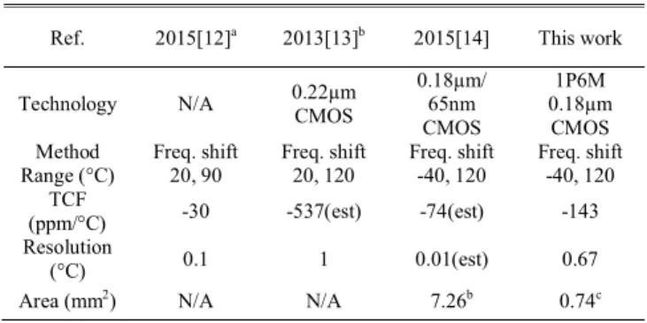
IV. DESIGN PARAMETERS AND MEASUREMENT RESULTS The proposed resonator structures were designed and simulated with CoventorWare. The area of the resonant structure is 301.2 x 288.6µm. The minimal gap is 2.6µm and the simulated resonant frequency is 41.1 kHz. The movement and resonant frequency response of actual sensor dies are measured by the MEMS Motion Analyzer (MMA). Fig. 5 shows the die photo of the temperature sensor test chip and white light interferometer (WLI) image of the proposed resonator structure. The sensor sensitivity is -5.7Hz/°C (-143ppm/°C) in the temperature range between -40°C and 120°C. The measurement results across eight dies are shown in Fig. 6. The measured resonant frequencies f0 at room
temperature are between 38.5 kHz and 38.8 kHz with displacements of 0.5~0.8m. The average measured frequency is less than the simulation result possibly due to that the mass of via layers was not considered in the simulation.
Fig. 7 shows simulation and measurement results of the proposed structure with modified spring turns. The resonant frequency is 14.94 kHz by simulation and 15.4 kHz by measurement. The overestimation of spring constant of the modified spring structure in the simulation may lead to the lower simulated resonant frequency than the average measured resonant frequency. Q factor changes from 2566 to 452 when the air pressure changes from 130 to 1600 Pa. The measured Q factor is lower than simulation possibly due to that only damping effect of the interdigitated finger structures rather than the whole structure was considered in the FEA simulation due to the computational complexity.
The proposed dual-mass accelerometer/gyro sensor structure is 2.5mm2. It resonates at 6.3 kHz for both driving and sensing
frequencies by design. The measured driving and sensing frequencies are 6.8 kHz and 7 kHz respectively, as shown in Fig. 4. Based on the measurement result of more than 90% finger overlap by WLI, the proposed structure shall achieve the sensitivity of more than 4.0 aF per degree/s.
V. SOCINTEGRATION
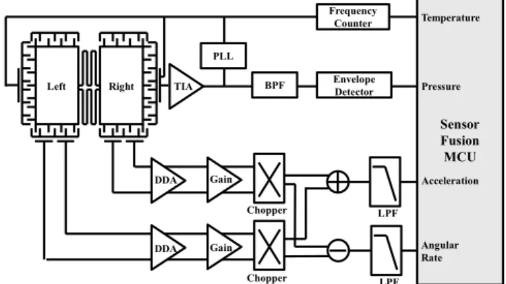
Fig. 8 shows the proposed architecture for the multi-sensor
SOC integration. The PLL provides the constant driving voltage for the resonator and the sensing capacitance variation is proportional to the quality factor of the resonator. Based on the architecture, integration of temperature can be done by monitoring the clock frequency. A frequency counter is used for counting PLL output frequency to track the frequency shift due to temperature. Ambient pressure sensing is done by measuring capacitance variation using a 133dB TIA. The TIA is followed by a band-pass filter to improve SNR. The envelope detector detects the amplitude of the filtered output for quality factor measurement. The proposed interdigitated finger and dual-mass structure driven by the PLL allows differential sensing of acceleration and angular rate for the accelerometer and gyro applications. Table I, II, and III show performance comparison between prior works with the proposed resonator-based monolithic sensors fabricated by the ASIC/MEMS CMOS process.
VI. CONCLUSION
The resonator-based MEMS structures have been developed and demonstrated using the 0.18m 1P6M CMOS ASIC/MEMS process. Multiple sensing functions for environmental temperature, ambient pressure, accelerometer and gyro can be integrated monolithically with the proposed SOC architecture. Performances of the proposed structures were compared with other discrete designs in this paper. Other sensing functions such as magnetic sensing based on Lorentz
Fig. 8. Schematic of the readout circuit
Left Right TIA
DDA DDA Gain Gain Chopper Chopper LPF PLL BPF Envelope Detector Frequency Counter LPF Sensor Fusion MCU Temperature Pressure Acceleration Angular Rate
2168-6734 (c) 2016 IEEE. Translations and content mining are permitted for academic research only. Personal use is also permitted, but republication/redistribution requires IEEE permission. See http://www.ieee.org/publications_standards/publications/rights/index.html for more information.
This article has been accepted for publication in a future issue of this journal, but has not been fully edited. Content may change prior to final publication. Citation information: DOI 10.1109/JEDS.2017.2666821, IEEE Journal of the Electron Devices Society
JEDS-2016-11-0134-R.R1 4
force could also be implemented using the proposed structures with coil circuits [6]. An MCU IP commonly available under the 1P6M 0.18um ASIC process can be embedded to acquire sensing signals from multiple sensors for data conversion and sensor fusion. With the resonator-based building blocks, the proposed multi-sensor SOC architecture could enable compact and multi-functional sensor designs for the emerging wearable and IOT applications.
REFERENCES
[1] D. E. Serrano, R. Tabrizian and F. Ayazi, "Tunable piezoelectric MEMS resonators for real-time clock," 2011 Joint Conference of the IEEE International Frequency Control and the European Frequency and Time Forum (FCS) Proceedings, San Fransisco, CA, 2011, pp. 1-4. doi: 10.1109/FCS.2011.5977885
[2] K. R. Cioffi and Wan-Thai Hsu, "32KHz MEMS-based oscillator for low-power applications," Proceedings of the 2005 IEEE International Frequency Control Symposium and Exposition, 2005., Vancouver, BC, 2005, pp. 551-558. doi: 10.1109/FREQ.2005.1573992
[3] C. T. C. Nguyen and R. T. Howe, "An integrated CMOS micromechanical resonator high-Q oscillator," in IEEE Journal of Solid-State Circuits, vol. 34, no. 4, pp. 440-455, Apr 1999. doi: 10.1109/4.753677
[4] W.-C. Chen and W. Fang, and S.-S. Li, “A generalized CMOS-MEMS platform for micromechanical resonators monolithically integrated with circuits,” in J. Micromech. Microeng., vol. 21, no. 6, 2011, pp. 065012. doi: 10.1088/0960-1317/21/6/065012
[5] H. G. Barrow, T. L. Naing, R. A. Schneider, T. O. Rocheleau, V. Yeh, Z. Ren, C. T.-C. Nguyen, "A real-time 32.768-kHz clock oscillator using a 0.0154-mm2 micromechanical resonator frequency-setting
element," 2012 IEEE International Frequency Control Symposium Proceedings, Baltimore, MD, 2012, pp. 1-6. doi: 10.1109/FCS.2012.6243740
[6] B. Bahreyni and C. Shafai, "A Resonant Micromachined Magnetic Field Sensor," in IEEE Sensors Journal, vol. 7, no. 9, pp. 1326-1334, Sept. 2007. doi:10.1109/JSEN.2007.902945
[7] W. Wai-Chi, A. A. Azid, and B. Y. Majlis, “Formulation of stiffness constant and effective mass for a folded beam,” in Archives of Mechanics, vol. 62, pp. 405-418, 2010.
[8] Q. Li, J. F. L. Goosen, F. van Keulen and J. T. M. van Beek, "Gas ambient dependence of quality factor in MEMS resonators," Sensors, 2009 IEEE, Christchurch, 2009, pp. 1040-1043. doi: 10.1109/ICSENS.2009.5398588 [9] F. R. Blom, S. Bouwstra, M. Elwenspoek, and J. H. J. Fluitman,“Dependence of the quality factor of micromachined silicon beam resonators on pressure and geometry”, in J. Vac. Sci. Technol. B, vol. 10, Issue 1, pp. 19-26, Jan 1992. doi:10.1116/1.586300
[10] H. Y. Hung, D. R. Chang and W. P. Shih, "Design and simulation of a CMOS-MEMS gyroscope with a low-noise sensing circuit," 2010 International Symposium on Computer, Communication, Control and Automation (3CA), Tainan, 2010, pp. 253-256. doi: 10.1109/3CA.2010.5533538
[11] Shih-Wei Lai and Jean-Fu Kiang, "A CMOS-MEMS single-chip dual-axis gyroscope," 2009 4th International Microsystems, Packaging, Assembly and Circuits Technology Conference, Taipei, 2009, pp. 305-307. doi: 10.1109/IMPACT.2009.5382177
[12] H. Fatemi, M. J. Modarres-Zadeh and R. Abdolvand, "Passive wireless temperature sensing with piezoelectric MEMS resonators," 2015 28th IEEE International Conference on Micro Electro Mechanical Systems (MEMS), Estoril, 2015, pp. 909-912. doi: 10.1109/MEMSYS.2015.7051107
[13] R. Mahameed, M. Abdelmoneum, D. Duarte, G. Taylor, S.-J. Choi, R. Brain, P. Morrow, and P. Fischer, "Fully monolithic MEMS based thermal sensor in 22 nm CMOS technology for SoC thermal managemet," 2013 Transducers & Eurosensors XXVII: The 17th International Conference on Solid-State Sensors, Actuators and Microsystems (TRANSDUCERS & EUROSENSORS XXVII), Barcelona, 2013, pp. 734-737. doi: 10.1109/Transducers.2013.6626871 [14] Y. Zhu, Y. Zheng, and Y. Gao, "An Energy Autonomous 400 MHz
Active Wireless SAW Temperature Sensor Powered by Vibration Energy Harvesting," in IEEE Transactions on Circuits and Systems I: Regular Papers, vol. 62, no. 4, pp. 976-985, April 2015. doi: 10.1109/TCSI.2015.2402937.
[15] S. Banerji, P. Michalik, D. Fernández, J. Madrenas, A. Mola, and J. Montanyà, "CMOS-MEMS resonant pressure sensors: optimization and validation through comparative analysis," Microsystem Technologies, pp. 1-17, 2016. doi:10.1007/s00542-016-2878-3.
[16] A. D. Sundararajan and S. M. R. Hasan, "Elliptic Diaphragm Capacitive Pressure Sensor and Signal Conditioning Circuit Fabricated in SiGe CMOS Integrated MEMS," in IEEE Sensors Journal, vol. 15, no. 3, pp. 1825-1837, March 2015. doi: 10.1109/JSEN.2014.2367416
[17] J. A. Montiel-Nelson, J. Sosa, R. Pulido, A. Beriain, H. Solar and R. Berenguer, "Digital output MEMS pressure sensor using capacitance-to-time converter," Design of Circuits and Integrated Circuits (DCIS), 2014 Conference on, Madrid, 2014, pp. 1-4. doi: 10.1109/DCIS.2014.7035565.
[18] Ming Hui Chang and Han Pang Huang, "Simulation and characterization of a CMOS-MEMS gyroscope with parasitic-insensitive sensing," 2008 IEEE Workshop on Advanced robotics and Its Social Impacts, Taipei, 2008, pp. 1-6. doi: 10.1109/ARSO.2008.4653593
[19] S. R. Chiu, C. Y. Sue, L. P. Liao, L. T. Teng, Y. W. Hsu and Y. K. Su, "A fully integrated circuit for MEMS vibrating gyroscope using standard 0.25um CMOS process," 2011 6th International Microsystems, Packaging, Assembly and Circuits Technology Conference (IMPACT), Taipei, 2011, pp. 315-318. doi: 10.1109/IMPACT.2011.6117258 TABLEII
PERFORMANCE COMPARISON OF PRESSURE SENSORS
Ref. 2016[15] 2015[16] 2014[17] This work Technology 250 nm CMOS BEOL SiGe CMOS MEMS Metal MUMPs 1P6M 0.18μm CMOS Sensor type Square Plate Resonator Diaphragm Diaphragm Comb- Finger Resonator Pressure
sensing Q-factor Capacitive Capacitive Q-factor Range (kPa) 0.1~100 10~100 0~30 0.1~1.6 Area (mm2) 0.0196 0.56 0.36 0.119
TABLEIII
PERFORMANCE COMPARISON OF GYRO SENSORS
Ref. 2008[18] 2010[10] 2011[19] This work Technology 0.35μm CMOS MEMS TSMC 0.35μm 1P5M&SOI 0.25μm 1P6M 0.18μm CMOS Qd 100 10 N/A 100 Qs 100 10 N/A 10 Sensitivity (mV/ o/sec) 1.186 0.476 7 10.48 Dyn. Range ( o/sec) 700 N/A +100 +50 Mech. Noise ( o/s/Hz-1/2) 0.0438 12.72 0.051 3.377
Area(mm2) N/A N/A 6.25 2.5
TABLEI
PERFORMANCE COMPARISON OF TEMPERATURE SENSORS
Ref. 2015[12]a 2013[13]b 2015[14] This work
Technology N/A 0.22µm CMOS 0.18µm/ 65nm CMOS
1P6M 0.18µm
CMOS Method Freq. shift Freq. shift Freq. shift Freq. shift Range (°C) 20, 90 20, 120 -40, 120 -40, 120
TCF
(ppm/°C) -30 -537(est) -74(est) -143 Resolution
(°C) 0.1 1 0.01(est) 0.67
Area (mm2) N/A N/A 7.26b 0.74c a Without readout circuit.
b Two chips are wire bonded. (Estimated) c Including sensor structure and PLL readout circuit

![[102-2] WNFA lab4 - A Tiny Wireless Sensor Network 2014/5/12 Chih-Hsien Ou](data:image/gif;base64,R0lGODlhAQABAIAAAP///wAAACH5BAEAAAAALAAAAAABAAEAAAICRAEAOw==)