Optical Fiber Technology 13 (2007) 170–173
www.elsevier.com/locate/yofte
S-Band long-distance fiber Bragg grating sensor system
C.-H. Yeh
a,∗, M.-C. Lin
b, B.-C. Cheng
b, S. Chi
b,caInformation and Communications Research Laboratories, Industrial Technology Research Institute, Chutung, Hsinchu 310-40, Taiwan bDepartment of Photonics, Institute of Electro-Optical Engineering, National Chiao Tung University, Hsinchu 300-10, Taiwan
cDepartment of Electrical Engineering, Yuan Ze University, Chungli 320-03, Taiwan Received 19 July 2006; revised 21 November 2006
Available online 29 January 2007
Abstract
We propose and investigate experimentally a sigma fiber laser scheme, which uses multiple fiber Bragg grating (FBG) sensors as the feedback elements, for a long-distance sensor system with 20-km long in S-band at first. By tuning a wavelength selective filter located in a laser cavity over the gain bandwidth, the laser selectively lases at each of the fiber Bragg wavelengths of the sensors, thus allowing strain-induced shifts in the Bragg wavelengths to be monitored. In our experiment, an S-band four-sensor system is proposed and investigated experimentally.
©2007 Elsevier Inc. All rights reserved.
Keywords: FBG; S-Band; Fiber sensor; EDFA
1. Introduction
Fiber Bragg gratings (FBGs)-based sensors [1] are currently receiving considerable research interest. These devices will prove to be useful for sensing a wide range of measured pa-rameters, especially strain and temperature. In particular, the development of a quasi-distributed, multipoint, strain measure-ment system for use as an embedded sensor in advanced com-posite materials or other structural elements is of great interest. Current areas of research include fabrication techniques [2], wavelength shift demodulation schemes [3,4], multiplexing ap-proaches [5] and fiber Bragg grating based laser sensor con-cepts [6–8]. Recently, an S-band (1470–1530 nm) amplification technique, which employs the erbium-doped silica fiber with the depressed cladding design and 980-nm pump laser to gen-erate erbium-doped fiber (EDF) gain extension effect, has been reported [9]. Therefore, the fiber sensor technique is expected to extend to S-band by using this S-band erbium amplifier.
In this paper, we employ an S-band erbium-doped fiber am-plifier (EDFA) and the sequential UV-writing FBGs [10] by using ring laser scheme for a long-distance sensor system. The multiple fiber Bragg grating (FBG) sensors are regarded as the
* Corresponding author.
E-mail address: [email protected] (C.-H. Yeh).
feedback elements. By tuning a wavelength selective filter lo-cated into the laser cavity over the S-band gain bandwidth, the laser selectively lases at each of the Bragg wavelengths of the sensors. Strain-induced shifts in the Bragg wavelengths of the sensors are detected by the shift in the lasing wavelengths of the system. Results obtained using four sensor elements in an S-band region are presented.
2. Experiments and results
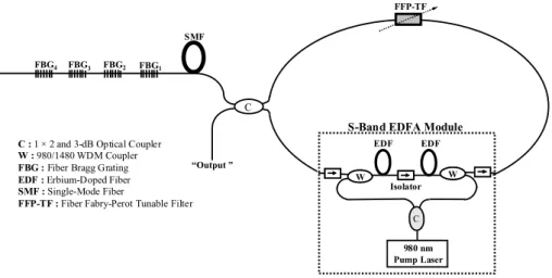
Figure 1 shows the experimental setup of the proposed 20-km long multiplexed FBG-based sensor system and EDF ring laser configuration. The proposed architecture composes of an S-band EDFA consists of two stage EDFA and a power-sharing 980 nm laser, a fiber Fabry–Perot tunable filter (FFP-TF), a 2× 2 optical coupler, and four FBGs with different central wavelength. These S-band FBGs were manufactured by sequential UV-writing method by using the interferomet-ric side-diffraction technique [1]. The central wavelengths and reflectivities of the FGB1 to FBG4 are 1511.4 nm and 92%, 1513.4 nm and 93%, 1515.7 nm and 96%, and 1517.4 nm and 83% at room temperature, respectively. The 3 dB bandwidth of those FBGs are nearly 0.4 nm.
The FFP-TF is an all-fiber device having a widely tunable range, low insertion loss (<0.5 dB), and low polarization-1068-5200/$ – see front matter © 2007 Elsevier Inc. All rights reserved.
C.-H. Yeh et al. / Optical Fiber Technology 13 (2007) 170–173 171
Fig. 1. Experimental setup of the proposed multiplexed FBG sensor system and S-band EDF ring laser configuration.
Fig. 2. Gain spectra of an S-band EDFA for 0 and−20 dB m input signal power over an effectively amplification bandwidth of 1480 to 1520 nm.
dependent loss (PDL) of∼0.1 dB. This FFP filter having the free spectral range (FSR) of 44 nm and 3 dB bandwidth of 0.4 nm can provide wavelength selection in the ring laser cavity by applying external voltage (<12 V) on the piezoelectric trans-ducer (PZT) of FFP filter. The optical outputs are observed by an optical spectrum analyzer (OSA) with a 0.05 nm resolution. Generally, the communicated wavelengths in fiber commu-nication were used at 1.3 or 1.5 µm bands. Moreover, the com-mon fiber sensors operated at 1.5 µm band. The proposed laser scheme can retrieve the larger output powers, and the entire lasing wavelengths are distributed over S-band. Therefore, the S-band bandwidth is a new operating band for the fiber grat-ing sensors. In other words, this proposed fiber laser scheme not only avoids covering the communication bands, but can be used to detect the long distance multi-point FBG sensor system. The S-band EDF inside EDFA module has a depressed cladding design in order to provide a sharp, high-attenuation, long-wavelength cutoff filter into active fibers. The erbium-doped fibers in the first and second stages have different charac-teristics. The fiber in the first stage has the fiber length of 20 m, and can provide low noise figure and medium gain by forward pumping. The fiber in the second stage has the fiber length of 30 m, and can produce large output power by backward pump-ing. In addition, the optical isolator between these two stages can reduce backward amplified spontaneous emission (ASE)
Fig. 3. Laser output at four different lasing wavelengths corresponding to the four FBG sensor wavelengths.
and improve noise figure performance. The total pump power of this amplifier module can be up to 280 mW while the bias current is operated at 356 mA. Figure 2 shows the gain spectra of an S-band EDFA for 0 and−20 dB m input signal power over an effectively amplification bandwidth of 1480 to 1520 nm. A peak gain can reach 35.7 dB at 1508 nm for input power of −20 dB m, and the saturated output power at 1496 nm can be up to 14.3 dB m for input power of 0 dB m, as shown in Fig. 2. The proposed fiber laser configuration containing the S-band erbium-doped gain section is a loop reflected which operates in a unidirectional manner due to the inclusion of an isolator. The other cavity reflection point provides by one of a series of FBG elements at nominally different wavelengths. The FBG el-ements serve as the sensors and can be connected as part of the cavity via a single mode fiber link of 20-km long. Due to the in-clusion of the wavelength filter within the loop reflector, lasing of the system occurs only when the filter transmission passband is aligned in wavelength with one of the Bragg elements.
Figure 3 shows the optical output spectra of the sensor sys-tem for the case where the FFP-TF is tuned to sequentially address each FBG. As can be seen, the fiber ring laser is forced to lase at a series of wavelengths: 1511.4, 1513.4, 1515.7, and 1517.4 nm, as determined by each central wavelength of the FBG. The signal-to-noise ratios (SNRs) of the four lasing wave-lengths is larger than 45 dB. From Fig. 3, the output powers of
172 C.-H. Yeh et al. / Optical Fiber Technology 13 (2007) 170–173
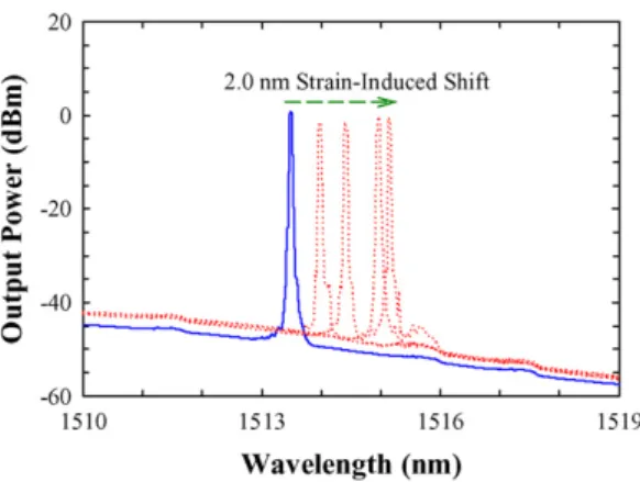
Fig. 4. The lasing wavelength spectra at the different strains (0–2000 µε) were applied on FBG2(λ2= 1513.4 nm).
Fig. 5. Strain versus the reflected wavelength observed at the output port, when the different strains (0–2000 µε) were applied on FBG2(λ2= 1513.4 nm). the four lasing wavelengths are 1.8, 0.3,−2.8, and −2.9 dB m, respectively.
When the external strain is applied on one FBG, then the las-ing central wavelength will begin to shift slightly. In the strain measurement, the tuning voltage of FFP-TF was manually ad-justed to optimize the output power, and thus tracked the FBG wavelength shift. Therefore, Fig. 4 shows the lasing wavelength spectra observed at the output port, when the different strains (0–2000 µε) were applied on the FBG2(λ2= 1513.4 nm). Fig-ure 5 also shows the strain versus reflected wavelength at 0– 2000 µε. The shift of the reflected wavelength is nearly 2 nm as the maximum strain is applied on the FBG, as shown in Fig. 5. Moreover, the reflected wavelength from FBG2 also shifts to 1514.62 nm when the temperature rises to∼90◦C.
The stability of proposed laser is with respect to the envi-ronmental parameters, such as the temperature, length of ring cavity, pressure, strain, etc. In our proposed ring laser scheme, the total cavity length was nearly 20-km long. The proposed laser scheme is operated at 25◦C to reduce the environmental variable. The lasing wavelength also has slightly drift due to the long cavity length and the FFP-TF. When a uniform lasing wavelength was observed, the maximal wavelength variation of nearly 0.08 nm was retrieved during a short-term observ-ing time of 100 s. However, the lasobserv-ing wavelength only was swept by the FFP-TP promptly to detect the wavelength drift when the strain or temperature on the FBG is changed.
There-fore, the stability of the laser is not key issues for fiber grating sensors.
Compared with the post study [11], the proposed sensor system can be used for long distance grating sensors and this proposed laser does not need the high power pump laser to pump Er3+ fiber. However, Ref. [11] cannot detect the long distance sensors. To achieve a long distance fiber sensor, the hybrid Raman laser and erbium laser were used to serve as a light source [12]. Nevertheless, the hybrid type needs to consume much cost. Therefore, the proposed laser scheme by wavelength-swept operation has the advantages of cost-effective, simply structure, S-band operating range, and high SNR for the long distance multi-point fiber grating sensors.
Due to the inhomogeneous effect of semiconductor optical amplifier (SOA), the entire lasing wavelengths by SOA-based multi-point fiber grating sensors [13] could be observed simul-taneously. That sensors detected in a short distance (∼1.5 km), and the lasing powers were small than that of EDFA-based [5].
3. Conclusion
In summary, we have proposed and investigated a novel and simply method for addressing a long distance FBG sensor sys-tem based on an S-band EDF ring laser scheme. The proposed S-band laser uses a unidirectional loop reflector, which contains a tunable wavelength selective filter. Tuning of this element pro-vide for selective operation of the laser at each of the Bragg wavelengths. Determination of the Bragg wavelengths can then be used to monitor the local condition, e.g., temperature or strain, at the FBG location. In our experiment, an S-band four-sensor system is proposed and investigated experimentally.
Acknowledgments
This work was supported in part by the National Science Council (NSC) of Taiwan, ROC, under grants NSC 95-2221-E-155-059 and NSC 95-2221-E-155-072. Authors thank K.-C. Hsu and Professor Y.-C. Lai for help with the experiments.
References
[1] G. Meltz, W.W. Morey, W.H. Glenn, Formation of Bragg gratings in op-tical fiber by a transverse holographic method, Opt. Lett. 14 (1989) 823– 825.
[2] C.G. Askins, I.E. Tsai, G.M. Williams, M.A. Puttman, M. Bashkansky, E.J. Friebele, Fiber Bragg reflectors prepared by a single exciter pulse, Opt. Lett. 17 (1992) 833–835.
[3] S.M. Melle, K. Liu, R.M. Measures, A passive wavelength demodulation system for guided-wave Bragg grating sensors, IEEE Photon. Technol. Lett. 4 (1992) 516–518.
[4] A.D. Kersey, T.A. Berkoff, W.W. Morey, High resolution fiber Bragg grat-ing based strain sensor with interferometric wavelength shift detection, Electron. Lett. 28 (1992) 236–238.
[5] A.D. Kersey, W.W. Morey, Multi-element Bragg-grating based fiber-laser strain sensor, Electron. Lett. 29 (11) (1993) 964–965.
[6] A.T. Alavie, S.E. Karr, A. Othonos, R.M. Measures, A multiplexed Bragg grating fiber laser sensor system, IEEE Photon. Technol. Lett. 5 (1993) 1112–1114.
[7] G.A. Ball, W.W. Morey, P.K. Cheo, Fiber laser source/analyzer for Bragg grating sensor array interrogation, J. Lightwave Technol. 12 (1994) 700– 703.
C.-H. Yeh et al. / Optical Fiber Technology 13 (2007) 170–173 173
[8] S. Kim, H. Yoon, S.B. Lee, S.S. Choi, B. Lee, Multiplexed strain sensor for long-distance remote sensing using fiber grating-tuned fiber laser scheme, in: CLEO Pacific Rim ’99 Tech. Dig., Seoul, Korea, 1999, pp. 324–325. [9] C.H. Yeh, C.C. Lee, C.Y. Chan, S. Chi, S-Band gain-clamped
erbium-doped fiber amplifier by using optical feedback method, IEEE Photon. Technol. Lett. 16 (2004) 90–92.
[10] K.C. Hsu, L.G. Sheu, K.P. Chuang, S.H. Chang, Y. Lai, Fiber Bragg grating sequential UV-writing method with real-time interferometric side-diffraction position monitoring, Opt. Express 13 (2005) 3795–3801.
[11] S.H. Yun, D.J. Richardson, B.Y. Kim, Interrogation of fiber grating sensor arrays with a wavelength-swept fiber laser, Opt. Lett. 23 (1998) 843– 845.
[12] Y.-J. Rao, Z.-L. Ran, R.-R. Chen, Long-distance fiber Bragg grating sensor system with a high optical signal-to-noise ratio based on a tunable fiber ring laser configuration, Opt. Lett. 31 (2006) 2684–2686.
[13] S. Kim, J. Kwon, S. Kim, B. Lee, Multiplexed strain sensor using fiber grating-tuned fiber laser with a semiconductor optical amplifier, IEEE Photon. Technol. Lett. 13 (2001) 350–351.
![[102-2] WNFA lab4 - A Tiny Wireless Sensor Network](data:image/gif;base64,R0lGODlhAQABAIAAAP///wAAACH5BAEAAAAALAAAAAABAAEAAAICRAEAOw==)