國 立 交 通 大 學
電子工程學系 電子研究所碩士班
碩 士 論 文
以 NafionTM/高分子材料為結構的感測層應用在
pH-ISFET 離子選擇場效電晶體之研究
The study of NafionTM/polymer structure based
sensing films on pH-ISFET applications
學生: 陳敬岦
Student: Jin-Li Chen
指導教授: 張國明 博士
Advisor: Dr. Kow-Ming Chang
以 NafionTM/高分子材料為結構的感測層應用在
pH-ISFET 離子選擇場效電晶體之研究
The study of NafionTM/polymer structure based
sensing films on pH-ISFET applications
研 究 生:陳敬岦 Student:Jin-Li Chen
指導教授:張國明 博士 Advisor:Kow-Ming Chang
國 立 交 通 大 學
電子工程學系 電子研究所碩士班
碩 士 論 文
A ThesisSubmitted to Department of Electronics Engineering & Institute of Electronics
College of Electrical and Computer Engineering
National Chiao Tung University
in Partial Fulfillment of the Requirements
for the Degree of
Master
in
Electronics Engineering June 2007
Hsinchu, Taiwan, Republic of China
以 NafionTM/高分子材料為結構的感測層
應用在 pH-ISFET 離子選擇場效電晶體之研究
學生:陳敬岦 指導教授:張國明 博士
國立交通大學
電子工程學系 電子研究所碩士班
摘 要
離子感測場效電晶體(Ion-sensitive Field Effect Transistor)是由 Bergveld 在 1970 年首先提出,由於它的尺寸小,反應速度快、可承受外部應力, 且與現今的 CMOS 製程相容,所以在現在的感測元件開發中具有相當大的潛力。 但是由於缺乏一個穩定的固態參考電極使得 ISFET 的應用受到很大的限制。 這個問題在藉由一個 ISFET/REFET 差動對的輸出後,固態參考電極因為金屬/溶 液接面產生的不穩定電壓會以共模訊號的形式而被消除掉。 在本篇論文中,我們首創以 Nafio 混合光阻(FH6400)的結構來修飾 ISFET 的 感測層,成功地使得原本對氫離子有高靈敏度的 ZrO2-pH-ISEFT 變成一個對氫離 子及鈉離子靈敏度極低的參考電晶體(REFET)。從實驗結果顯示原本氫離子靈敏 度有 57.89 mV/pH 的 ZrO2-pH-ISFET 經過 Nafion 與光阻混合物的修飾後可降低 到 5.8 mV/pH,而鈉離子的靈敏度也可從 15.88 mV/pNa 降低到 11.27 mV/pNa。 為了要實現一個最簡單且小型結構的 ISFET,也就是把一個固態電極整合到 單一 ISFET 晶片上,不需額外再使用到 REFET 或玻璃電極。我們也把 Nafion 與 光阻混合的結構應用到固態參考電極的表面修飾上。因為從前面的實驗結果可知
道,Nafion 混合 PR 的結構具有使 REFET 的感測層維持在一個固定的電位且保護 它不受離子的干擾的效果。由實驗結果可看出,令人困擾的電壓不穩問題,大幅 地獲得改善。一個單一的 ISFET 整合固態參考電極在不需搭配 REFET 或玻璃參考 電極的情況下,對氫離子的靈敏度在 60 秒的量測時間中仍然可達到 55.9 mV/pH 而且輸出電壓也相當的穩定。
The study of NafionTM/polymer structure based
sensing films on pH-ISFET applications
Student: Jin-Li Chen Advisor: Dr. Kow-Ming Chang
Department of Electronics Engineering & Institute of Electronics
National Chiao Tung University
ABSTRACT
ISFET( Ion-sensitive Field Effect Transistor ) was first developed by Bergveld in
1970s, and because of its small size, fast response, rigidity and compatibility with
standard CMOS process, ISFET is an attractive candidate of modern sensor device.
But the lack of a stable solid-state reference electrode is detrimental to the luring
properties of ISFET. One approach to solve this problem is to use a differential
measurement consisting of an ion-sensitive structure (ISFET) and an ion-insensitive
structure (REFET). With this arrangement, the common mode unstable voltage
generated from the thermodynamically undefined metal/ electrolyte interface can be
eliminated.
In this thesis, we first apply the Nafion mix PR(FH6400) structure to modify the
ISFET sensing layer and successfully make the high H+ sensitivity ZrO2-pH-ISFET
become a low H+ and Na+ sensitivity REFET. From the experimental results, the H+
sensitivity of ZrO2-pH-ISFET with the value of 57.89 mV/pH can be decreased to 5.8
mV/pH and Na+ sensitivity is also decreased from 15.88 mV/pNa to 11.27 mV/pNa.
sensitivity will be 52.09 mV/pH and 4.61 mV/pNa, respectively.
In order to realize the single ISFET integrated with a solid-state reference
electrode, the simple and compact structure of ISFET sensor without the additional
REFET or glass reference electrode, we also apply the Nafion mix PR structure for
the solid-reference electrode. From the previous experimental results, we can know
the Nafion mix PR structure can maintain a constant voltage for the sensing layer of
REFET and prevent it from the ions disturbing. The experimental results show the
troublesome and unstable problem can be greatly improved. Without REFET
arrangement in differential measurement or replaced by glass reference electrode, the
H+ sensitivity of single ZrO2-pH-ISFET integrated with solid-state reference
electrode still can reach to 55.9 mV/pH and the output voltage is also very stable
誌 謝
能夠完成此論文,首先要感謝張國明老師在我徬徨無助的時候給於我的幫 助,讓我能夠重新接觸到這多采多姿的碩士生活。老師那豁達開朗的個性,讓我 印象深刻,並且也教導了我許多待人處世的道理,讓我的想法觀念成長了不少。 要不是老師適時的提攜學生,我想我不會那麼快地從挫敗中站起來。 還有感謝龔正老師,王水進老師,鄧一中老師在口試中對我論文內容提出的 建議及看法,讓我對研究的題目有更進一步的想法,也讓我見識到了教授思考問 題的方法,確實是學生該去學習的。 其次我要感謝張知天學長及趙高毅學長,在我實驗過程中給於的建議及鼓 勵,使我對於實驗充滿了信心,而且在平常的交談中也傳受了我許多人生的經驗 談,讓我受益匪淺。還有感謝鄧至剛學長 Pt 鈀材的熱情贊助,使得本篇論文內 容更佳的完整。另外我要感謝佳鴻及其他實驗室同學在儀器考核及實驗上的幫 助,有了你們讓我可以很快地進行實驗,順利完成我的碩士論文。 最後要感謝我的父母,在我的求學生涯中,你們從不會給予我任何的壓力, 讓我可以自由自在的學習,在我遇到挫折失敗時,你們也都給予我極大的關心與 幫助,讓我覺得相當幸福及幸運。還有我的母親,這幾年的風風雨雨,辛苦妳了, 由於妳無怨無悔的付出,讓我可以無後顧之憂,順利完成我的學業,取得碩士學 位。 誌于 2007.07 陳敬岦Contents
Abstract
(in Chinese)
--- iAbstract
(in English)
--- iiiAcknowledgement
--- vContents
--- viTable Captions
--- viiiFigure Captions
--- ixChapter 1
Introduction
1.1 The Importance of pH Detection--- 11.2 The pH glass electrodes--- 1
1.3 The ISFET-base pH sensors--- 3
1.4 The all solid-state reference electrodes of ISFET--- 6
1.5 Motivation of this work and thesis organization--- 6
1.6 References--- 7
Chapter 2
Theory Description
2.1 What is pH? --- 92.2 Basic principles of ISFET--- 9
2.2.1 From MOSFET to ISFET--- 10
2.2.2 The oxide-electrolyte interface--- 11
2.2.3 The pH sensitivity of ISFET--- 16
2.3 Non-ideal phenomena of ISFET: Hysteresis and Drift --- 18
2.3.1 Hysteresis--- 18
2.3.2 Drift--- 18
2.4 Summary--- 21
2.5 References--- 21
Chapter 3
Experiment and Measurement
3.1 ISFET and REFET fabrication Process flow--- 253.2 Key steps illustration--- 26
3.3 Measurement system--- 28
3.3.1 Current-Voltage (I-V) measurement set-up--- 28
3.3.2 Current-Voltage (I-V) measurement set-up with solid reference electrode--- 29
3.4 References--- 29
Chapter 4
Results and Discussions
Part I: Polymer-based material applied as the sensing layer 314.1 H+ and Na+ Sensitivity of different polymer-based material-- 31
4.1.1 H+ and Na+ Sensitivity of ZrO2--- 32
4.1.2 H+ and Na+ Sensitivity of NF coated ZrO2--- 32
4.1.3 H+ and Na+ Sensitivity of NF-P3HT-ZrO2--- 33
4.1.4 H+ and Na+ Sensitivity of NF-P3HT-HMDS-ZrO2--- 33
4.1.5 H+ and Na+ Sensitivity of NF-PR-ZrO2--- 34
4.1.6 H+ and Na+ Sensitivity of NF-PR-HMDS-ZrO2--- 34
4.1.7 H+ and Na+ Sensitivity of NF-mix-PR-ZrO2--- 35
4.1.8 H+ and Na+ Sensitivity of NF-mix-PR-HMDS-ZrO2--- 35
4.1.9 Summary of Part I--- 36
Part II Solid-State Reference Electrode integrated with ISFET 36 4.2 Solid-State Reference Electrode--- 36
4.2.1 The glass reference electrode--- 37
4.2.2 The bare solid-state reference electrode--- 37
4.2.3 The NF coated solid-state reference electrode--- 38
4.2.4 The NF-PR coated solid-state reference electrode--- 38
4.2.5 The NF-mix-PR-HMDS coated solid-state reference electrode--- 38
4.2.6 Summary of Part II--- 39
4.3 Conclusion--- 39
4.4 References--- 40
Table Captions
Table 3-1 ZrO2 Sputtering parameters
Table 3-2
The test structures of REFET
Table 4-1 H+ sensitivity of NF-P3HT-ZrO2 Table 4-2 H+ sensitivity of NF-P3HT-HMDS-ZrO2 Table 4-3 H+ sensitivity of NF-PR-ZrO2 Table 4-4 H+ sensitivity of NF-PR-HMDS-ZrO2 Table 4-5 H+
sensitivity of NF-mix-PR ZrO2
Table 4-6 H+
sensitivity of NF-mix-PR-HMDS-ZrO2
Table 4-7 Summary of H+
and Na+ sensitivity in different test structures
Figure Captions
Fig 1-1
Conventional pH glass electrode
Fig 1-2
ISFET Cross-Section Structure
Fig 1-3 Encapsulation of the ISFET chip in the sensor for in vivo measurements in gynaecology
Fig. 1-4
Block diagram of a differential ISFET/REFET measuring system
Fig 2-1
MOSFET and ISFET cross-section structure
Fig 2-2
ID-VDS curve of an ISFET with Vgs(a), and pH (b) as a parameter
Fig 2-3 Site-binding model Fig. 2-4 Hemholtz model Fig. 2-4 Gouy-Chapman model Fig. 2-6 Gouy-Chapman-Stern model
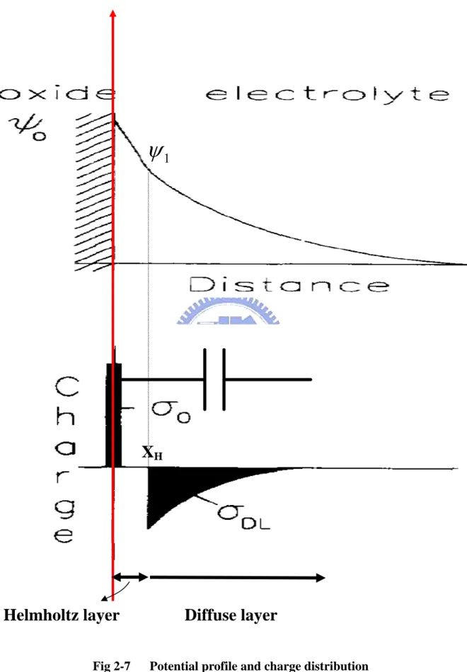
Fig 2-7 Potential profile and charge distribution
at an oxide electrolyte solution interface Fig 2-8
Electrode and electrolyte interface
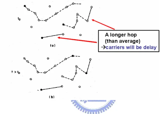
Fig 2-9 tSchematic representation of carriers hopping through a random array of sites
Fig. 3-1
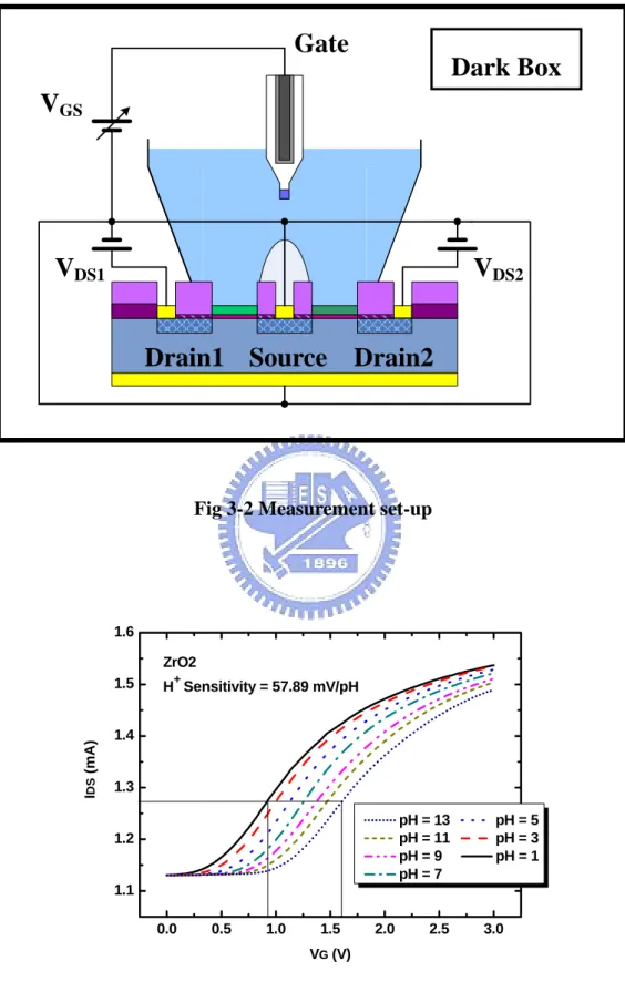
Fig 3-2
Measurement set-up
Fig 3-3
Extraction method of sensitivity
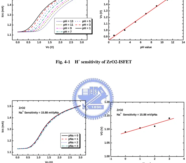
Fig. 4-1
H+ sensitivity of ZrO2-ISFET
Fig. 4-2
Na+ sensitivity of ZrO2-ISFET
Fig. 4-3 Nafion chemical structure and model
Fig. 4-4
H+ sensitivity of NF-ZrO2-ISFET
Fig. 4-5
Na+ sensitivity of NF-ZrO2-ISFET
Fig. 4-6
The chemical structure of P3HT
Fig. 4-7
H+ sensitivity error bar of NF-P3HT-ZrO2
Fig. 4-8
H+ sensitivity of NF-P3HT-ZrO2
Fig. 4-9
Na+ sensitivity of NF-P3HT-ZrO2
Fig. 4-10
H+ sensitivity error bar of NF-P3HT-HMDS-ZrO2
Fig. 4-11 H+
sensitivity of NF-P3HT-HMDS-ZrO2
Fig. 4-12 Na+
sensitivity of NF-P3HT-HMDS-ZrO2
Fig. 4-13 H+
Fig. 4-14 H+
sensitivity of NF-PR-ZrO2
Fig. 4-15 Na+
sensitivity of NF-PR-ZrO2
Fig. 4-16
H+ sensitivity error bar of NF-PR-HMDS-ZrO2
Fig. 4-17 H+
sensitivity of NF-PR-HMDS-ZrO2
Fig. 4-18 Na+
sensitivity of NF-PR-HMDS-ZrO2
Fig. 4-19 H+
sensitivity error bar of NF-mix-PR ZrO2
Fig. 4-20
H+ sensitivity of NF-mix-PR ZrO2
Fig. 4-21
Na+ sensitivity of NF-mix-PR ZrO2
Fig. 4-22 H+
sensitivity error bar of NF-mix-PR-HMDS- ZrO2
Fig. 4-23
H+ sensitivity of NF-mix-PR-HMDS- ZrO2
Fig. 4-24
Na+ sensitivity of NF-mix-PR-HMDS- ZrO2
Fig. 4-25
The summary of H+ and Na+ sensitivity in different test structures
Fig. 4-26 The sensitivity of ZrO2-pH-ISFET measure by glass reference electrode
Fig. 4-27 The long-term stability and sensitivity linearity of ZrO2-pH-ISFET measured by bare solid-state reference electrode
Fig. 4-28 The long-term stability and sensitivity linearity of ZrO2-pH-ISFET measured by NF coated solid-state reference electrode
Fig. 4-29 The long-term stability and sensitivity linearity of ZrO2-pH-ISFET
measured by NF-PR coated solid-state reference electrode
Fig. 4-30 The long-term stability and sensitivity linearity of ZrO2-pH-ISFET measured by NF-mix-PR-HMDS coated solid-state reference
electrode
Fig. 4-31 The long-term stability and sensitivity linearity of ZrO2-pH-ISFET
measured by NF-mix-PR-HMDS coated solid-state reference
Chapter 1
Introduction
1.1 The importance of pH detections
pH is an important parameter in many fields such as agricultural, chemistry, food chemistry, pharmaceutic industry and human health [1]. For example, the body fluid of living organisms usually has specific pH range. If the pH of the human blood changes by a little as 0.03pH units or less the functioning of the body will be greatly impaired [2]. In our surroundings, the pH values of rivers, waters and soils affect the livability of fishes, animals and plants. A little change of the pH value will result big impact to these organisms.
In order to detect the pH value, there are many methods for using such as (1) indicator reagents (2) pH test strips (3) metal electrode (4) glass electrode. The mentioned methods (1) and (2) are differentiated from colors and can not reach high accuracy. The method (3) is difficult for handling and reproducing. The method (4) glass electrode commonly is used and considered to be the standard measuring methods. Therefore in the next section we will have an introduction for the pH
glass electrode, which plays an important role in pH detections.
1.2 The pH glass electrodes
The first pH glass electrode is developed by Cremer in 1906 and after that many efforts have been devoted to improve its application. The glass electrode is composed of a bulb of glass membrane, which permits the passage of hydrogen ions, and a fixed
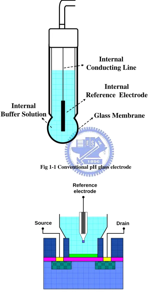
concentration of HCl or a buffered chloride solution inside in contact with an internal reference electrode, which use of Ag/AgCl, as shown in Fig. 1-1.
When the glass electrode is immersed in the solution, the outer bulb surface becomes hydrated (the thickness is about 0.3-0.6nm) and exchanges sodium ions for hydrogen ions to build up a surface layer of hydrogen ions [2]. For the purpose of good and stable sensing glass, the sensing glass often contained other component like Na2O-CaO-SiO2, Li2O-BaO-SiO2, Li2O-Cs2O-La2O3-SiO2, et al. [3]. For example, the
introducing of alkali (ex. Li) oxide will break the stable Si-O bond and result the change between Li+ and H+:
( _ ) ( )
SiO Li− + glass membrane +H+ solution
( _ ) ( )
SiO H hydrated layer Li solution+
→ − + +
The produced charges will transport by Li+, and build up surface potential. The potential difference between the outside and inside glasses will be delivered to the pH meter and exhibit the potential difference in pH value. The potential difference across the glass membrane can be derived from Nernst equation.
E Eo RT ln H
nF α +
= + where E=electrode potential, Eo=standard potential of the electrode, R=gas constant (8.31441JK-1mol-1), T=temperature (in Kelvin), n=valance (n=1 for hydrogen ions), F=Faraday constant and αH+=activity of hydrogen ions.
Nernst equation shows that, providing that at one side of the interface the activity of the ion of interest is kept constant, the electrode potential is a direct logarithmic function of the ion activity on the other side [4]. Because the glass electrode has the ideal Nernstian response, so it is most widely used for pH measurement. One more to be noted is for the purpose of stable and endurable property, the reference electrode material must use the noble metal like Ag, Pt, et al, it
is relatively expensive. Because of the internal liquid reference solutions, the traditional glass electrode must measure at vertical position for chemical stability, it is inconvenient in applications. Therefore in order to overcome these disadvantages, the all-solid-state pH glass electrode sensors have been investigated [1] [3] [5].
As mentioned before, the property of glass electrode has improved by many efforts, but due to its brittle nature and difficult to miniaturize, it is still hard to be used in food or in in vivo applications, especially for biomedical applications. There is an increasing need for alternative pH sensors.
According to Ref [2], there are some new techniques for pH detection: (1) Optical-fiber-based pH sensors (2) Mass-sensitive pH sensors (3) Metal oxide pH sensors (4) Conducting polymer pH sensors (5) Nano-constructed cantilever-based pH sensors
(6) ISFET-based pH sensors (7) pH-image sensors As shown above, the ISFET-based pH sensor is a new techniques for pH detection and because of the nowadays advanced IC fabrication techniques, it has a big potential for widely application.
1.3 The ISFET-based pH sensors
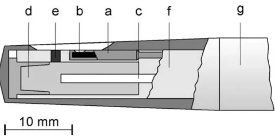
ISFET (Ion-Sensitive field effect transistor) was first developed in the 1970s as an alternative to the fragile glass electrode for the measurement of pH and concen- trations of ions (Na+, K+, Cl-, NH4+, Ca2+, etc.) [6]. The ISFET structure is similar to the MOSFET except that metal gate electrode is removed and deposit a sensing film on the gate oxide, as shown in Fig 1-2. The upmost sensing layer will have chemical reactions with the test solution and build up charges at the surface. Surface charges will induce surface potential and change the threshold voltage of the ISFET, hence the
operation current ID will also change. For instance, in linear region the operation current ID is given by 2 1 [( ) ] 2 d ox GS t SD DS W I C V V V V L μ = − −
Therefore, in order to be able to measure the threshold voltage of the ISFET- and hence the solution pH-it is necessary to bias it at constant drain current (ID) and
constant drain to source voltage(VDS). In such situation there will be only two
variables, VG and Vt. When Vt varies, the gate voltage must adjust by an equal
amount to compensate. The circuit to maintain constant ID and constant VDS can be
carrying out by using feedback OP amplifiers and current sources and sinks [7]. Different pH concentrations will induce different voltage variation, so we can determine the pH value of the test solution from the potential difference. The more detailed operation mechanisms and theories are presented in Chapter 2.
Because of removing the gate electrode, the input gate voltage will be applied through a reference electrode, which provides a stable potential in the electrochemical measuring system, as shown in Fig 1-2. We can see that the big glass electrode is in- convenient and easily broken in measurement, so the small and rigid solid state reference electrode is investigated.
One of the frustrations in the field of solid-state chemical potentiometric as well as amperometric sensors is the lack of a solid-state reference electrode [8], [9]. If the solid-state Ag/AgCl reference electrode is contacting directly with the electrolyte solution ( this often referred as ”quasi-reference electrodes ” ), then the chlorine ion will diffuse into the electrolyte solution and the electrode is susceptible to changing activity of its primary ion(e.g. a(Cl-) in Ag/AgCl system). Hence, the lifetime of this pH sensor is short and the stability of this pH sensor is bad [10], [11].One way to solve this unstable problem is encapsulating the separate reference electrode in a
separate compartment filled with internal reference electrolyte of constant Cl- activity like Fig. 1-3. Because due to out-diffusion of KCl and in-diffusion of ions frome the sample solution, the stable lifetime of these electrodes is limited and to seal a small volume of saturated KCl electrolyte is also a mass production fabrication challenge.
Another way to solve the unstable problem is using the REFET (Reference Field Effect Transistor). REFET is identical with ISFET except that REFET does not react on the ion concentration to be measured, i.e. REFET is insensitive to the test ion concentration [8]. By using differential ISFET/REFET measuring system, the unstable problem of quasi-reference electrode can be solved. As shown in Fig. 1-4, the unstable signal of the quasi-reference electrode (common mode signal) will be suppressed through the differential amplifier, and the output signal will only be a function of pH.
Most of the attempts to create a REFET are based on covering the gate oxide of an ISFET with an additional ion insensitive membrane, such as Teflon [8]. The key parameter for the choice of the membrane was initially the hydrophobicity, but later on one discovered that this is not the only criterion for chemical inertness as required for a REFET. According to the ISFET theory which will be discussed in Chapter 2, the sensitivity parameter (α ) has an important related factor, βint. The larger βint the larger sensitivity, and βint is correlated to the number of the surface sites. Therefore, the surface modification by chemical methods to reduce the numbers of the surface sites is also a way to diminish the sensitivity.
As mentioned above, there are two methods to reduce the unstable problem of the solid-state reference electrode. But method one, reference electrode with internal reference electrolyte, has its difficulty in package and miniaturization. Method two needs one more REFET and more circuits, so need more layout areas. Not only the mentioned disadvantages of using REFET but also the separated referenced electrode will restrict applicability. Hence to develop an all solid-state reference electrode
integrated with ISFET in one chip is desirable.
1.4 The all solid-state reference electrodes of ISFET
The most simple and compact structure of ISFET is the all solid-state reference electrode integrated with ISFET in a single chip. But the solid-reference electrode is a big problem to prevent from realizing.
Up to now, it is still a problem to create a long-term stable all solid- state reference electrodes. This is because the potential at the solid/liquid interface is thermodynamically undefined and will lead to significant errors in pH measurement. The unstable problem may come from the redox reaction or other chemical reactions at the metal reference electrode and the liquid interface, i.e. the solid/liquid interface. Hence, building up a stable potential at the interface is a way to realize the all solid-state references integrated with ISFET.
1.5 Motivation of this work and thesis organization
As mentioned before, the unstable problem of the quasi-reference electrodes can be solved by co-fabricated REFET. The destination of fabricating a REFET is insensitive to the pH concentration and other metal ions such as Na+, K+, Ca+, or chloride, Cl-. According to the reference literatures [8], [12], [13], the sensing layer of a REFET is nothing more than the macromolecule, i.e. high polymer-based materials. Therefore, in this thesis, we firstly fabricated an ISFET with zirconium oxide (ZrO2) as the sensing layer. The sensitivity of ZrO2-pH-ISFET is about 57.89 mV/pH, it is approximate to the Nernstian sensitivity of 59.2mV/pH , and Na+ sensitivity of the ZrO2- pH-ISFET is about 15.88mV/pH.
Secondly, variety of polymer-based material such as Nafion, P3HT, photo resister (PR-FH6400) were used as the sensing layer of REFET. We find out the pH sensi- tivity of the ZrO2- pH-ISFET could be greatly decreased by these polymer-based materials. In order to find a best REFET for ZrO2- pH-ISFET, we also measure the Na+ sensitivity of the REFET. We want in differential measurement, the REFET can eliminate the unstable voltage from the quasi-reference electrode and also decrease the other ions, especially the sodium and potassium ions, sensitivity of ZrO2-ISFET.
After the above study of low sensitivity REFET, we then coat the polymer-based materials at the solid-state reference electrode. According to our previous experiment shows that the polymer-based materials make REFET have low sensitivity, it means that the surface potential is a constant value, i.e. the surface potential will be stable. Based on this idea, we coat the polymer-based materials at the solid-state reference electrode. We find that it works at the solid-state reference electrode, the stability of the output voltage (VG) is greatly improved.
In chapter 2, the basic theory and non-ideal phenomenon of ISFET is introduced and the detail process flow of this experiment will be mentioned in chapter 3. In chapter 4, we will have some discussions about our experimental results and in chapter 5, the future work of this experiment is presented.
1.6 References
[1] H. Kaden, H. Jahn, M. Berthold, ”Study of the glass/polypyrrole interface in an all-solid-state pH sensors”, Solid State Ionics, vol. 169, pp. 129-133, 2004.
[2] Y. Q. Miao, J. R. Chen and K. M. Fang, “New technology for the detection of pH”, J. Biochem. Biophys. Methods, vol. 63, pp. 1-9, 2005.
vol. 32, No.2, pp.54-57, Feb., 2004.
[4] P. Bergveld, “ISFET, Theory and Practice”, in IEEE Sensor Conference, Toronto, Oct. 2003.
[5] A.Noll, V. Rudolf, E. W. Grabner, ”A glass electrode with solid internal contact based on Prussian blue”, Electrochemica Acta, vol. 44, pp.415-419, 1998
[6] Miao Yuqing , Guan Jianguo, Chen Jianrong, “Ion sensitive field transducer-based biosensors”, Biotechnology Advances, vol. 21, pp.527-534, 2003.
[7] Paul A. Hammond, Danish Ali, and David R. S. Cumming, ”Design of a Single-Chip pH Sensor Using a Conventional 0.6-μm CMOS Process.”, IEEE Sensors Journal, vol. 4, no. 6, Dec, 2004.
[8] P. Bergveld, “Thirty years of ISFETOLOGY What happened in the past 30 years and what happen in the next 30 years”, Sensors and Actuators B, vol. 88, pp. 1-20, 2003.
[9] W. Oelbner, et al., ”Encapsulation of ISFET sensor chips”, Sensors and Actuators B, vol. 105, pp.104-117, 2005.
[10] Chung-We Pan, Jung-Chuan Chou, I-Kone Kao, et al., ”Using Polypyrrole as the Contrast pH Detector to Fabricate a Whole Solid-State pH Sensing Device”, IEEE Sensors Journal, vol. 3, no. 2, pp.164-170, April, 2003.
[11] I-Yu Huang, Ruey-Shing Huang, Lieh-His Lo, ”Improvement of integrated Ag/AgCl thin-film electrodes by KCL-gel coating for ISFET applications”, Sensors and Actuators B, vol. 94, pp. 53-64, 2003.
[12] Michal Chudy, Wojciech Wroblewski, Zbigniew Brzozka, ”Towards REFET”, Sensors and actuators B, vol. 57, pp.47-50, 1999.
[13] A. Errachid, J. Bausells, N. Jaffrezic-Renault, ”A simple REFET for pH detection in differential mode”, Sensors and Actuators B, vol. 60, pp.43-48, 1999.
Chapter 2
Theory Description
2.1 What is pH?
The concept of pH was first introduced by Danish chemist S. P. L. Sørensen in 1909. pH is a measure of the acidity or basicity of a solution, solutions with pH more than 7 are considered basic, while those with pH less than 7 are considered acid. pH 7 is neutral because it is the pH of pure water at 25℃. The name, pH, can be derived from a combination of “p” the word power “H” for the symbol of the element hydrogen [1]. The formula for caluating pH value is defined as:
pH = −log10α[H+] (2-1) where α is the activity coefficient and [H+] is the molar concentration of solvated protonsin units of moles per liter. From equation (2-1) we can know that pH reflects the mount of available hydrogen ions not the concentration of hydrogen ions.
2.2 Basic principles of ISFET
Ion-selective field effect transistors (ISFETs) were first developed by P. Bergveld in the 1970s.The ISFET structure is similar to MOSFET (Metal Oxide Semiconductor Field Effect Transistor), besides the gate electrode is replaced by a reference electrode and inserted in an aqueous solution which is in contact with the gate sensing layer. Why we use a reference electrode is because that a capacitor (with the gate oxide as the dielectric) needs two connections, in this case respectively the silicon and the electrolyte [2]. Besides without the referenced electrode the electrolyte potential will
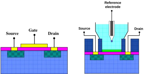
be unstable and is influenced by noise easily. A schematic structure of MOSFET and ISFET are shown in Fig. 2-1.
2.2.1 From MOSFET to ISFET
Because the structures are similar, the basic operational mechanisms are alike. For both MOSFET and ISFET, the drain current in the non-saturated region is
[( ) 1 2] 2 d ox gs t ds ds W I C V V V V L μ = − − (2-2) where Cox is the oxide capacity per unit area. W an L is the width and length of the
channel, respectively, and μis the electron mobility in the channel. We can see that if the fabrication process is controlled well and biased in well designed applied electronic circuits, the geometric parameter CoxW
L
β μ= , as well as the drain-source voltage Vds, and the threshold voltage Vt are constant, then the drain current Id will be
only the function of Vgs in MOSFET. But in the ISFET, because the oxide/electrolyte
interface will have a chemical reaction and build up charges at the interface which produce an electrostatic potential distribution, then it will have a modification at Vt. As well-known, the threshold voltage of MOSFET is
M Si ox ss B 2 t f ox Q Q Q V q C φ −φ + + φ = − + (2-3) where the first term reflects the difference in the workfunction between the gate metal(φM) and the silicon (φSi), the second term is due to accumulated charge in the oxide(Q ), at the oxide-silicon interface(ox Q )and the depletion charge in the ss silicon(Q ),whereas the last term determines the onset of inversion depending on the B doping level of silicon [2].
In the case of ISFET, two more difference has to be noted, the interfaces between the liquid and the gate oxide on the one side and the liquid and the reference
electrode at the other side [3]. The interface potential at the gate oxide-electrolyte interface is determined by the surface dipole potential of the solutionχsol, which is a constant, and the surface potential ψo which results from a chemical reaction, usually governed by the dissociation of oxide surface group. And then the interface potential between the liquid and the reference electrode is the reference electrode potential relative to vacuum Eref. Hence the ISFET threshold voltage becomes
si ox ss B 2 t ref o sol f ox Q Q Q V E q C φ ψ χ + + φ = − + − − + (2-4)
note that the work function of metal gate φM in equation (2.3) seems to be disappeared, but this is not true, because it is “burried” by the term Eerf [2]. Take a look at equation (2.4), we can find that all the term are constant exceptψo, it is the term which makes the ISFET sensitive to the electrolyte pH. The parameterϕo is a function of solution pH value and is determined by surface chemical reaction at the sensing layer (oxide layer).According to the above-mentioned, we can know that the ISFET drain current Id is a function of Vgs and Vt, i.e. (I Vd gs, )V ,and Vt t is a function of surface potential ψo, i.e. ( )V ψo ,whereψois a function of pH. From Fig. 2-2 we can see these results obviously [2].
An ISFET is electronically identical to a MOSFET, but with one more feature: the possibility to chemically modify the threshold voltage via the interfacial potential at the oxide/electrolyte interface, so in the next section we will have a statement at the oxide/electrolyte, that is the key point of ISFET.
2.2.2 The oxide-electrolyte interface
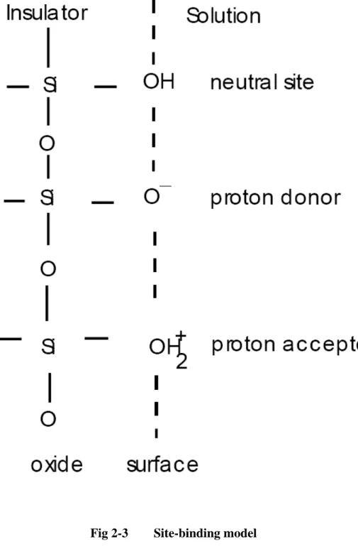
oxide/electrolyte interface will build up charges and develop an electrostatic potential. But what is the charging mechanism at the surface? The site-binding model introduced by Yate et al. is the most well-known approaches to describe the charging mechanism at the oxide/electrode interface as illustrated in Fig 2-3. The surface of any metal oxide (the sensing layer ) always contains hydroxyl groups, for instance, in the case of silicon dioxide is SiOH groups. The amphoteric sites may donate or accept a proton from the solution, leaving a negatively charged or positively charged surface group respectively. The surface reactions are:
AOH R AO−+HB+ (2-5) AOH+HB+ R AOH2+ (2-6) where A is the metal oxide component, such as Si, Al, Zr, Ta, and HB+ represents the
protons in the bulk of the solution. We also have to know that there are a fixed number of surface sites per unit area, Ns
2
S AOH AOH AO
N =ν +ν + +ν − (2-7)
Base on some electrochemical knowledge and math derivation, we can get the surface charge density [ / 2] o C m σ
(
)
2 o q AOH AO qB σ = ν + −ν − = − (2-8)where B is the number of negatively charged groups minus the number of positively charged groups in mole per unit area. We can see that when the number of positively and negatively charged groups on the surface is equal and consequently there will be no net charge on the surface. In this condition, we say the pH value at the point of zero charge is pHpzc. One more thing we have to know is that different operations of
ISFETs (flat band condition and linear region) will yield different value of pHpzc [7].
2 2 S S S a b H o a b b H H a K K qNs K K K a a σ + + + ⎛ − ⎞ ⎜ ⎟ = ⎜ + + ⎟ ⎝ ⎠ (2-9) where Ka and Kb are dissociation constant. A detailed derivation can see the Ref. [3] [4]. After we get the surface charge density, we can find the intrinsic buffer capacity
int
β ,the capability of the surface to store charge as result of a small change in the H+ concentration, defined as o int S S B q q pH pH σ β ∂ ∂ = − = − ∂ ∂ (2-10) from equation (2-9) and (2-10)
(
)
2 2 int 2 2 4 2.3 S S S S S b H a b H a b S H a b b H H K a K K a K K N a K K K a a β + + + + + + + = + + (2-11)It is called “intrinsic” buffer capacity, because it is only capable of buffering small changes in the surface pH (pHs) and not in the bulk pH (pHb). We can see that
the value of Ns, Ka and Kb are oxide dependent. More surface sites will have larger
int
β . According to Ref. [4], Hydrolysis of the surface will create more surface sites and thus a rise in the intrinsic buffer capacity and the sensitivity.
Not only the surface reaction will affect the surface charge density but also the background electrolyte will influence the surface charge [4]. This dependence is ascribed to variations in the double layer capacitance. For reasons of charge neutrality the surface charge σois balanced by an equal but opposite charge, σdl, in electrolyte. The two opposite charges, σoandσdl, parallel to each other form the electrical double layer structure, and the integral electrical double-layer capacitance is named Cdl i, . The relation between then is
,
dl o Cdl i o
σ = −σ = − ×ψ (2-12) where the potential difference ψo =ψ ψs− B, the surface potential subtracts the bulk potential of the electrolyte.
But what is the detailed mechanism for the electrical double layer? It needs a theory model to describe this. The first double layer model is proposed by Helmholtz in 1853. He regards the double layer as a parallel plate capacitance structure as shown in Fig. 2-4. The plate distance “r” is taken as the ion radius and the double layer capacitance Cdl Q
V
= will be a constant value, where Q is the surface charge and V is the potential difference of the double layer. But from the experiment, we can know the double layer capacitance is not a constant value, so the Hemholtz is not suitable to describe the exact double layer structure. The Hemholtz model is merely suitable for the high concentration electrolyte. Because the potential difference will be large in high concentration electrolyte and the double layer structure will be like the parallel plate capacitance.
Because the Helmholtz model only considers the electrostatic force, therefore it can not model the relation between the double layer capacitance and electrolyte concentration. In the begging of 20th century, Gouy and Chapman proposed the idea of a diffuse layer to interpret the capacitive behavior of an electrode/electrolyte as shown in Fig. 2-5. They think that the ions in the solution are not only electrostatically attracted to the electrode surface but also the attraction is counteracted by the random thermal motion which acts to equalize the concentration through the solution. The ions concentration in the electrolyte will obey the Boltzmann equation: ( ) oexp i x i z q C x Ci kT φ − ⎛ ⎞ = ⎜ ⎟ ⎝ ⎠ (2-13) where φx is the potential at any distance x with respect to the bulk of the solution,
( ) i
C x and Ci are the molar concentration od species i at a distance x and in the bulk o
of the solution respectively and Z is the magnitude of the charge on the ions. The i relation between ionic activity (a ) and ions concentration (i c ) is i ai = × , where fi ci
i
f is activity coefficient, in diluted electrolyte f will be approach unity. But the i
Gouy-Chapman model has one major drawback, the ions are considered as point charge that can approach the surface arbitrarily close. This will cause unrealistic high concentrations of ions near the surface at high values of ψo [4]. The Gouy-Chapman model can only suitable for low concentration electrolyte. This imply that the electrical double layer structure have to combine the Hemholtz and Gouy-Chapman model in certain way.
In 1924, Stern combined this two double layer model, named Gouy- Chapman- Stern model. The Gouy-Chapman-Stern model, which combines the Helmholtz single adsorbed layer with the Gouy-Chapman diffuse layer, is most widely used to describe the double layer structure in ISFET literature. The model describes that some of the ions in the electrolyte are next to the electrode surface and because of the finite ions size, the ions couldn’t approach the surface arbitrarily close. The other ions are distributed in the electrolyte according to the Boltzmann equation and form a charge diffuse layer in the electrolyte. There is a distance, xH , which is the closest plane for
the centers of the ions. Hence, the diffuse layer is starting from xH, and will possess
the same amount of charge σdl(of opposite sign) as oxide surface charge σo, because the Helmholtz layer is not containing any charge, as shown in Fig. 2-6 and Fig. 2-7. In Gouy-Chapman-Stern model, the double layer capacitance consists of a series network of a Hemholtz layer capacitance (Stern capacitance) and a diffuse layer capacitance. The difference between ψo and ψ1 is the potential difference across
the Stern capacitance. By the Gouy-Chapman-Stern model, we can get the critical parameter:differential double layer capacitance Cdif , the ability of the double layer to store charge in response to a small change in the potential, defined as
o dl dif o o C σ σ ψ ψ ∂ ∂ = = − ∂ ∂ (2-14)
According Ref. [3], the derived inverse Cdif is made up of two components in series: 2 2 0 1 1 1 1 2 cosh 2 o dif o Stern r o C C z q n zq kT kT ψ σ ε ε ψ ∂ = = + ∂ ⎛ ⎞ ⎜ ⎟ ⎝ ⎠ (2-15)
2.2.3 The pH sensitivity of ISFET
From above discussions, the sensitivity of pH ISFET is related to the intrinsic buffer capacity βint and the differential capacitance Cdif .By site-binding model and Gouy-Chapman-Stern model, we can get the values of βint and Cdif , respectively. The pH sensitivity is the change of the insulator-electrolyte potential,ψo, on a change of the bulk pH, o
B pH
ψ
∂
∂ .This expression is derived from a separate treatment of both sides of the double layer, i.e., the gate insulator and the electrolyte [8]. Therefore, from equation (2-10) and equation (2-14), we can get the effect of a small change in the surface pH (pHS) on the change in the surface potential ψo,
o o o int S o S dif q pH pH C ψ ψ σ β σ ∂ =∂ × ∂ =− ∂ ∂ ∂ (2-16)
Then by applying Boltzmann equation, the activity of the of the bulk protons B H
a +
can be related to the activity of the protons in the direct vicinity of the oxide surface S H a +, that is exp S B o H H q a a kT ψ + + − ⎛ ⎞ = ⎜ ⎟ ⎝ ⎠ (2-17) or in the from of pH 2.3 o S B q pH pH kT ψ = + (2-18) then equation (2-16) can be write in the form
int 2.3 o o dif B q q C pH kT ψ β ψ ∂ =− ⎛ ⎞ ∂⎜ + ⎟ ⎝ ⎠ (2-19)
rearrangement of equation (2-19), we can get a general expression for the sensitivity of the electrostatic potential to changes in the bulk pH,
o 2.3 B kT pH q ψ α ∂ = − ∂ (2-20) with 2 int 1 2.3 1 dif kTC q α β = + , 0< <α 1 (2-21)
the parameter α is a dimensionless sensitivity parameter that varies between 0 and 1 depending on βint and Cdif .When βintis high and Cdif is small enough, α will approaches 1. If α =1, the ISFET has a so-called Nernstain sensitivity of precisely -59.2 mV/pH at 298K, which is also the maximum achievable sensitivity.
The usual SiO2 from the MOSFET process does not fulfill the requirements of a
high valueβint. The pH sensitivity of SiO2 sensing film ISFET is only about 30mV/pH.
In order to find high sensitivity sensing film, many sensing layer have been investigated such as Si3N4 [9],[10], Al2O3 [9],[11], Ta2o5[9],[12], HfO2 [12], SnO2
[13].
The ISFET has many advantages over the conventional glass electrode, such as, small size, strong robustness, high input impedance, low output impedance, and rapid response [5][9].It seems to attractive for biomedical applications. But ISFET has two important time-dependent factors, drift and hysteresis, that will influence the output voltage accuracy and prevent the application. Therefore, it is importance to under- stand the mechanism of drift and hysteresis. In the next section, we will have some descriptions at these two unwanted mechanisms.
2.3 Non-ideal phenomena of ISFET: Hysteresis and Drift
The total response of pH-ISFET consists of three parts: fast response, slow response and drift. The response of an ISFET to a fast pH step is general characterized by a fast response, followed by a slow change in the same direction, i.e. slow response, and ultimately a drift which is linear or logarithmic with time [14].The fast response time is defined to be the time needed for the output to change from 10﹪to 90﹪of the total variation (at the order of ms or faster). The slow response is the extra time needed for the response to reach 100﹪. The drift is defined as the monotonic change of response after a proper time from the response (ex. 5 hours).
2.3.1 Hysteresis
The amplitude of the slow response is quite small ( 3﹪to 7﹪of the total pH response ) but will last for several hours[15]. This is because the slow response is correlated to the response of reactive sites in the bulk, i.e. buried sites, of the film, not like the fast response is related to the surface reaction [16],[17]. Because the ions have to diffuse to the buried sites for reaction, it will take a long time for response. The slow response will make small part of the pH response slowly, and occurs with a delay of the order of minutes to hours after the pH variation. There will have different output voltage, when the pH-ISFET was measured many times at the same pH value [18], and we call this phenomena is ” Hysteresis” or ”Memory effect”, still memory the original pH state.
When the intrinsic response (fast and slow response) is completed, the output voltage of the pH-ISFET still varies with time gradually and monotonically. This phenomenon is called ”Drift”. According to Ref [14], it is difficult to identify the cause of this phenomenon, which could be either a surface or a bulk effect, or both. Some possible causes of drift have been proposed [14]. In 1998, Jamasb proposed a physical model quantitatively explains drift in terms of hydration of the silicon nitride surface [19]. This is the first physical model that provides a quantitative description of the drift characteristics.
He proposed that the surface of a silicon nitride film is known to undergo a relatively slow conversion to a hydrated SiO2 layer or an oxynitride during contact with an aqueous solution. Since hydration alters the chemical composition of the nitride surface, then the dielectric constant of the overall insulator capacitance, i.e. the series combination capacitance of the superficial hydrated layer and that of the underlying silicon nitride, will exhibit a slow, temporal change. Consequently, the amount of the inversion charge stored in the semiconductor at a given gate bias slowly changes over time, giving rise to a monotonic temporal change in the threshold voltage [19]. The new idea sounds make sense for explaining drift mechanism. The author uses a new diffusion concept, dispersive transport, to model the transport mechanism.
Dispersive transport is proposed by Scher and Montroll in 1975 for explaining the phenomenon of the long tail photocurrent I(t) in photoconductor like As2Se3,which
can not be explained by traditional Gaussian diffusion theory [20] [21]. They use an stochastic transport model based on time-dependent continuous-time random walk to interpret dispersive transport. Dispersive transport does not depend on the details of any specific mechanisms, but characterizes the motion of a carrier subjected to a broad distribution of event times. The event times include 【1】 hopping times from
hopping transport 【2】 trap release times from multiple-trap transport 【3】 or both (1) and(2) that is from trap-controlled hopping transport. In ISFET, sites may be the buried sites beneath the sensing layer surface and traps may be the dangling bond in the sensing films.
The carriers transport in an amorphous insulating material, which considered as a network of localized sites, by a succession of hops from one site to another, as shown in Fig. 2-8. Because the distance between various neighboring sites have some variation than a mean value, the effective intersite transition rates
( )
r r/o /kTo
W rG =W e− e−Δ (2-22) where r is the difference in position, Δ is the energy level of the sites,r is the o radius of the local charge distribution. We can know that W r
( )
G is sensitive to the sites distance, and will suffer a wide statistical dispersion. This is turn yields a broad distribution of hopping times [20] [21]. The authors designate a hopping time distribution function ( )ψ t to describe the time distribution, the probability per unit time for a carrier to hop at a time t, at any sites when the previous hop occurred at t=0.( )t dt
ψ will be the probability that after a carrier arrives in a given cell.
And by Ref [22], Dispersive transport is characterized by a power-law time decay of the mobility or diffusivity of the form 1
tβ− , 0<β<1. Dispersive transport leads to a decay in the density of site/traps occupied by the species undergoing transport and the hydrated layer is essentially limited by dispersive transport in the presence of these sites/traps. The thickness of this hydrated layer will exhibit a stretched-exponential time dependence. That is
NS T/ ( )t NS T/ (0) exp
(
t/)
βτ
⎡ ⎤
Δ = Δ ⎣ − ⎦ (2-23) where ΔNS T/ ( )t is the area density (units of cm
-2) of sites/traps occupied,τ is the time
characterizing dispersive transport.
2.4 Summary
In this chapter, we have introduced the basic concepts and theories of ISFET. The ISFET operational mechanism is similar to the MOSFET. In a constant drain to source voltage VDS, the drain current will only controlled by VG, but in ISFET, the drain
current will also controlled by different pH values. Because there will be a chemical reaction at the oxide/electrolyte interface then build up charges and potential to change the drain current ID. We introduce the charging mechanism at the surface layer
by site- binding model introduced by Yate et al.. We also describe the background electrolyte will also influence the surface charge density, and we use the Gouy-Chapman-Stern model to describe this mechanism. By these two models, we can get the critical parameters βint, Cdif and derive the expression equation of
sensitivity o 2.3 B kT pH q ψ α ∂ = −
∂ . At the end of this chapter, we also mention the
non-ideal phenomena of ISFET, drift and hysteresis, which prevent the widespread application.
2.5 References
[1] Y. Q. Miao, J. R. Chen and K. M. Fang, “New technology for the detection of pH”, J. Biochem. Biophys. Methods, vol. 63, pp. 1-9, 2005.
[2] P. Bergveld, “Thirty years of ISFETOLOGY What happened in the past 30 years and what happen in the next 30 years”, Sensors and Actuators B, vol. 88, pp. 1-20, 2003.
[3] P. Bergveld, “ISFET, Theory and Practice”, in IEEE Sensor Conference, Toronto, Oct. 2003.
[4] R.E.G. van Hal et al. , “A general model to describe the electrostatic potential at electrolyte oxide interface”, Advance in Colloid and Interface Science, vol.69, pp.31-62, 1996.
[5] Miao Yuqing , Guan Jianguo, Chen Jianrong, “Ion sensitive field transducer-based biosensors”, Biotechnology Advances, vol. 21, pp.527-534, 2003.
[6] W. M. Siu, R. S. C. Cobbold, “Basic Properties of the Electrolyte-SiO2-Si System: Physical and Theoretical Aspects”, IEEE Transactions on Electron Device, vol. ED-26, NO. 11, Nov., 1979
[7] H.K. Liao, et al. ”Study on pHpzc and surface potential of tin oxide gate ISFET”, Materials Chemistry and Physics, vol. 59, pp.6-11, 1999
[8] R.E.G. van Hal, J.C.T. Eijkel, P.Bergveld, “A novel description of ISFET sensi- tivity with the buffer capacity and double layer capacitance as key parameters”, Sensors and Actuators B, vol. 24-25, pp.201-205, 1995.
[9] Tadayuki Matsuo, Masayoshi Esashi, ”Methods of ISFET Fabrication”, Sensors and Actuators, vol. 1, pp.77-96, 1981.
[10] Imants R. Lauks, Jay N. Zemel, “The Si3N4/Si Ion-Sensitive Semiconductor Electrode ”, IEEE Transactions on Electron Devices, vol. ED-26, no.12, pp. 1959- 1964, Dec., 1979.
[11] J.C. Chou, C.Y. Weng, “Sensitivity and hysteresis effect in AL2O3 gate pH- ISFET ”, Materials Chemistry and Physics, vol. 71, pp.120-124, 2001.
[12] P.D. van der Wal et al. ,”High-K Dielectrics for Use as ISFET Gate Oxide”, in Sensors, Proceedings of IEEE.2004.
[13] H.K.Liao et al.,” Study of amorphous tin oxide thin films for ISFET applications”, Sensors and Actuators B, vol.50, pp.104-109, 1998.
[14] Luc Bousse, Piet Bergveld, “The Role Of Buried OH Sites In The Response Mechanism Of Inorganic-Gate pH-Sensitive ISFETs”, Sensors and Actuators, vol. 6, pp.65-78, 1984.
[15] P. Woias, L.Meixner, P. Frostl, ”Slow pH response effects of silicon nitride ISFET sensors”, Sensors and Actuators B, vol. 48, pp.501-504, 1998.
[16] J.C. Chou, K.Y. Huang, J.S. Lin, ”Simulation of time-dependent effects of pH-ISFETs ” Sensors and Actuators B, vol. 62, pp.88-91, 2000.
[17] Luc Bousse et al. , ”Comparison of the hysteresis of Ta2O5 and Si3N4 pH-sensing
insulators”, Sensors and Actuators B, vol.17, pp. 157-164,1994.
[18] J.C. Chou, Y.F. Wang, ”Preparation and study on the drift and hysteresis properties of the tin oxide gate ISFET by the sol-gel method”, Sensors and Actuators B, vol.86, pp.58-62, 2002.
[19] S. Jamasb, S. D. Collins, R. L. Smith, ”A Physical Model for Threshold Voltage Instability in Si3N4-Gate H+-Sensitive FET’S ( pH ISFET’s )”, IEEE Transactions on Electron Devices, vol. 45, no. 6, pp.1239-1245, Jun, 1998. [20] H. Scher, Elliott W. Montroll, ”Anomalous transit-time dispersion in amorphous
solid”, Physical Review B, vol. 12, no.6, pp.2455-2477, Sep., 1975.
[21] G. Pfister, H. Scher, ” Time-dependent electrical transport in amorphous solid: As2Se3”, Physical Review B, vol. 15, no. 4, pp.2062-2082, Feb., 1977.
[22] J. Kakalios, R. A. Street, W. B. Jackson, ”Stretched-Exponential Relaxation Arising from Dispersive Diffusion of Hydrogen in Amorphous Sillicon”, Physical Review Letters, vol. 59, no.9, pp.1037-1040, Aug. 1987.
[24] S. Jamasb, S. D. Collins, R. L. Smith, ”A Physically-based Model for Drift in Al2O3-gate pH ISFETs ” in International Conference on Solid-State Sensors and Actuators Chicago, June, 1997.
[25] S. Jamasb, S. D. Collins, R. L. Smith, ”A physical model for drift in pH ISFET ”, Sensors and Actuators B, vol. 49, pp.146-155, 1998.
[26] George T. Yu, S.K. Yeh, ”Hydrogen ion diffusion coefficient of silicon nitride thin films”, Applied Surface Science, vol. 202, pp.68-72, 2002.
Chapter 3
Experiment and Measurement
3.1 ISFET and REFET fabrication Process flow
To investigate the properties of P3HT, PR, Nafion as the REFET up most sensing layers, the co-fabricated ISFET/REFET is presented. All processes were accomplished in Nano Facility Center. The fabrication procedures are listed as follows and the process is illustrated in Fig 3-1:
(a)
1. RCA clean.
2. Wet oxide growth 6000Ǻ, 1050°C, 65mins. (b)
3. Mask#1 to define Source/Drain region. 4. BOE wet etching of silicon dioxide.
5. Dry (Screening) oxide growth 300 Ǻ, 1050°C, 12mins.
6. Source/Drain implantation, Dose=5E15(1/cm2), Energy=25Kev. 7. Source/Drain annealing, 950°C, 30mins.
(c)
8. PECVD Oxide deposition 1μ m. (d)
9. Mask#2 to define contact hole and gate region. 10. BOE wet etching of silicon dioxide.
(e)
12. Mask#3 to define the sensing layer region.
13. Sensing layer (ZrO2) deposition by Sputtering.300 Ǻ.
14. ZrO2 sintering 600°C, 30mins. (f)
15. Mak#4 to define the contact and solid reference electrode region. 16. Ti/Pt deposition by Sputtering 150 Ǻ /350 Ǻ.
(g)
17. Backside Al evaporation 5000 Ǻ. 18. Pt and Al sintering 400°C, 30mins (h)
19. Coating the polymer-based material as REFET sensing layer.
3.2 Key steps illustration
In step 8, we deposit SiO2 film of 1μm thickness by PECVD, The 1μm SiO2 film can protect the structure of a pH-ISFET. During a long period of electrolyte immersing, ions may diffuse and affect the ISFET’s electrical characterization and a thick SiO2 can eliminate the effect.
In step 14, a ZrO2 sensing layer is deposited by sputtering. It has been proved the ZrO2 film deposited by sputtering has good characteristics as a pH-ISFET sensing layer in our lab. Therefore, in this study we still use ZrO2 as the sensing layer and research the the suitable REFET for it. Table 3-1 is the sputtering parameters. In step16, before depositing Pt we have to deposit Ti as the adhesion layer. The adhesion between Pt/SiO2 is very poor, so we have to deposit Ti to improve the adhesion.
REFET sensing layer. In this experiment, a three-layer structure is presented. Above the original sensing layer (ZrO2), a polymer-based material PR(FH6400) or P3HT is applied. After that, we coat Nafion above PR or P3HT as a passivation layer. In order to improve the adhesion of PR and P3HT with ZrO2, we apply HMDS before coating PR or P3HT. Besides the three-layer structure, a mix composition of Nafion and PR is also coating above the ZrO2 sening layer, we call this is an entrapment method. We think that this will reduce one coating time, and the interface induced uncertain problems of three-layer will also be reduced. The experiment test structures are listed in Table 3-2. Why we did not mix Nafion with P3HT is because they can not dissolve together.
According to the lectures, Nafon is extremely resistant to chemical attack and has relatively high working temperatures, so Nafion can protect the underlying polymer-based layer from damaging. There is also an additional advantage for using Nafion. That is Nafion is a cation exchange polymer, i.e. Nafion will not affect the hydrogen ions to pass and any sensitivity decreased will be from the contribution of polymer-based material. But, in our experimental experience, P3HT is very hydrophobic and PR(FH6400) is easy to dissolve in Nafion solutions, so the coating method and the quantity of liquid have to be controlled carefully, following is our process flow:
1. Dropping the PR or P3HT solution at the sensing layer region.
2. Dried in air for 6 hours, the solution becomes colloid with thickness of 5-10um.
3. Bake at 90°C for 5mins for the purpose of annealing and having a flat surface.
4. Dropping Nafion 2% solution above PR or P3HT with thickness of 2-3um. 5. Dried in air for 30mins
6. Baked at 90°C for 5mins to anneal Nafion film.
When dropping Nafion above PR(FH6400), we have to pay attention that Nafion solution must simultaneously cap the all parts of PR which coated at previous step, otherwise some part of PR will be etched entirely and cause damage to PR. This may be that PR is easy to dissolve in Nafion even PR become solid. If we cover all parts of PR, the dissolve stress will be equal at PR and PR film will be still fine, otherwise some parts of PR will against more stress and easy to break.
3.3 Measurement system
To investigate the characteristics of different polymer-based sensing layer, we measure the I-V curves for the pH-ISFET by using HP4156 as measurement tool and the system is shown in Fig 3-2. For preventing from light influence [2], the entire measurement procedures were executed in a dark box. The measured pH values are 1,3,5,7,9,11,13, and the pH buffer solution were supplied by Riedel-deHaen corp.
Preparation of NaCl solution is also needed in Na+ ions measurement. The NaCl salts are electronic grade and solutions are prepared in DI water with different mole concentrations, 10-3M, 10-2M, 10-1M, 1M .When preparation of NaCl solution, it have to know the solubility of Nacl at room temperature is about 37g Nacl per 100g water. In order to reduce the preparation error of mole concentration, we prepare 1M solution, and the other mole concentrations are diluted by DI water.
3.3.1 Current-Voltage (I-V) measurement set-up
A HP-4156 semiconductor parameter analyzer system were set up to measure the I-V characteristic curves, in which include IDS-VGS and IDS-VDS curves at controlled
temperature. It have to take care when dropping the pH-buffer solution at the sensing region. Because the sensing areas are small, prevention of air bubbles generated at the interface is needed to pay attention. In order to measure at more stable situation, every pH value is immersed for 30 seconds before measurement.
From IDS-VGS curves, we can extract the pH sensitivity (mV/pH) of ZrO2
pH-ISFET. At first, finding the point of maximum transconductance, i.e. the maximum slope of IDS-VGS curves, and getting the current value (IDS). At the constant
IDS of maximum transconductance, we can see that with different pH values the
reference electrode voltage (VG) is shifted and the shifted voltage per pH value is the
sensitivity, as illustrated in Fig. 3-3.
3.3.2 Current-Voltage (I-V) measurement set-up with solid reference
electrode
In this situation, we replace the glass reference electrode with solid reference electrode. The long-term stability of the output voltage (VG) is what we concern
about. Hence, as the same with measuring for sensitivity, ever pH value is immersed for 30 seconds before IDS-VGS measurement. Then the long-term stability of output
voltage is measured for 60 seconds with 15 seconds a measurement point.
3.4 References
[1]`K. M. Chang, K. Y. Chao, T. W. Chou, and C. T. Chang, ”Characteristics of Zirconium Oxide Gate Ion-sensitive Field-Effect Transistors” Japanese Journal of Applied Physics Vol. 46 No. 7A pp. 4334-4338 2007.
dioxide thin films deposited by MOCVD”, Applied Surface Science, vol. 214, pp.214-221, 2003
Chapter 4
Results and Discussions
Part I: Polymer-based material applied as the sensing layer of
REFET
4.1 H
+and Na
+Sensitivity of different polymer-based material
For solving the unstable voltage problem of solid-state reference electrode, a REFET (Reference ion-sensitive Field Effect Transistor) co-fabricated with ISFET is applied. The REFET is identical with ISFET but does not react on the ion concen- tration to be measured. By applying a differential measurement between ISFET and REFET, the unknown and unstable electrode potential manifests itself as common mode signal and is thus suppressed by the CMRR (common-mode-rejection-ratio) of the system.
According to Chapter 2, the sensitivity of ISFET is related to the numbers of surface sites, i.e., the more numbers of surface sites the larger sensitivity it has. For the sake of reducing sensitivity, we need to find an effective diffusion barrier for protons, thus reducing the pH sensitivity of the device. In this study, we want to build up a REFET which is suitable for the ZrO2-pH- ISFET, so to find a REFET with low H+ sensitivity is our main object. But a REFET must also insensitive to the other ion concentration, or else the H+ sensitivity of ISFET will be decreased by REFET in differential measurement. The alkali metal ions are easy to be found in electrolytes, so in this study, we also study the Na+ sensitivity of ISFET and REFET.
4.1.1 H
+and Na
+Sensitivity of ZrO
2Fig. 4-1 and Fig. 4-2 show theH+ and Na+ Sensitivity of ZrO2 is 57.89mV/pH and
15.88mV/pNa, respectively. It shows that the ZrO2 sensing film is more selective to H+ ions than Na+ ions. The results are agreed with Ref. [1]. The H+ sensitivity of ZrO2 sensing film will be a little decreased by Na+ ions in the electrolyte. So, if we find a REFET with Na+ sensitivity is similar to ZrO2, then the H+ sensitivity decreased by Na+ will also be eliminated in differential measurement.
4.1.2 H
+and Na
+Sensitivity of NF coated ZrO
2
In our experimental experience, the polymer-based material, PR and P3HT, are easy to damage in electrolyte, and the film properties will be unstable in measurement. In order to solve this problem, we apply Nafion developed by Dr. Walther Groot at DuPont in the late 1960’s.
Nafion is a perfluorinated polymer that contains small proportions of sulfonic or carboxy ionic functional groups and with this functional groups, Nafion has the feature of unique equilibrium ionic selectivities and the ionic transport properties. Fig. 4-3 shows the its chemical structure and model, we can see that Nafion can be divided into three parts: (A) a hydrophobic fluorocarbon backbone C-F (B) an interfacial region of relatively large fractional void volume (C) the clustered regions where the majority of the ionic exchange sites, counter ions, and absorbed water exists [2] [3] [4] [5].Because of the high concentration SO3-
ion clusters, Nafion exhibits a high cation conductivity, i.e., high cation exchange. And Nafion is modified from Teflon, so Nafion is extremely resistant to chemical attack and high working temperature.
coated above PR or P3HT. In order to see if the coated Nafion will influence any H+ sensitivity, we coated Nafion above ZrO2 sensing layer. Fig. 4-4 shows the NF-coated ZrO2 H+ sensitivity and Na+ sensitivity are 58.92mV/pH and 16.34mV/pNa, respectively. The sensitivity is a little increased by Nafion, because of its high cation conductivity property thus more cations will be easily trapped at the surface sites. This result means that Nafion will be exact a protective role, and will not decrease any sensitivity, so in the following experiment any decreased sensitivity will be from the contribution of PR or P3HT.
4.1.3 H
+and Na
+Sensitivity of NF-P3HT-ZrO
2
According to Ref. [6], deposition of hydrophobic ion-unblocking polymer layers is a way to design a REFET and such membranes exhibit slight conductivity. Based on this idea, we using the popular organic material, P3HT (poly (3-hexylthiophene) ) as the REFET sensing layer. P3HT is used as the semiconductor layer in FET, because it is easily processable and is compatible with plastic substrates. Fig. 4-6 shows the chemical structure of P3HT, we can see that P3HT is synthesized from polythiophene (PHT) with 3-alky substitutes in head to tail regioregular structure [7]. Because of ordering and crystallinity in its solid states, the mobility in P3HT will be improved. We think that the ordering structure of P3HT maybe an effective diffusion barrier for. protons. Table 4-1 and Fig. 4-7 ~ Fig. 4-9 is the H+ sensitivity and Na+ sensitivity of P3HT-ZrO2 structure. From Table 4-1, the sensitivity of P3HT is very unstable during measurement, it maybe come from the poor adhesion between P3HT and ZrO2. P3HT is very hydrophobic with contact angle more than 90°, and the original gate surface is hydrophilic, so the attachment will be weak. But we believe P3HT has the potential to reduce sensitivity because the once low sensitivity during measurement.
![Fig. 2-4 Hemholtz model [2-23].](https://thumb-ap.123doks.com/thumbv2/9libinfo/8104124.165304/61.892.144.751.119.393/fig-hemholtz-model.webp)