Time-multiplexed three-dimensional displays based
on directional backlights with fast-switching
liquid-crystal displays
Ko-Wei Chien and Han-Ping D. Shieh
An autostereoscopic display using a directional backlight with a fast-switching liquid-crystal (LC) display was designed and fabricated to obtain a better perception of 3D images by enhanced resolution and brightness. A grooved light guide in combination with an asymmetric focusing foil was utilized to redirect the emitting cones of light to the left and right eyes, respectively. By designing the groove structures of the focusing foil with rotation from⫺1.5° to 1.5° in the gradient and having the pitch ratio of the grooved light guide to the focusing foil of less than 3, the boundary angle then shifts from normal viewing and the moiré phenomenon can be suppressed. Cross talk of less than 6% and a LC response time of faster than 7.1 ms further improve the stereoscopic image perception. Additionally, 2D–3D compatibility is provided. © 2006 Optical Society of America
OCIS codes: 230.3720, 330.1400.
1. Introduction
As image display advances from monochromic to color, each development is driven by the pursuit of ever more natural visions. Therefore the stereoscopic display is seen to be a major advancement in providing human perception closer to reality. Autostereoscopic displays, which do not require a user to wear special glasses, are generally classified into the “holographic type,” the “volumetric type,” and the “stereo pairs’ type.” Never-theless, the holographic approach is usually con-strained in monochromic applications.1 Besides, the
volumetric type, which uses a laser beam to project the sketch of an object on a fast spinning plane, requires a bulky volume against the trend of thinness and light-weight of display technologies.2The stereo pairs’ type,
which can be further classified into the “spatial-multiplexed type” and the “time-“spatial-multiplexed type,” therefore becomes the most popular approach because of the compatibility with current LCD technologies.
For the spatial-multiplexed type, odd and even pixels of the panel control projected images to left and right eyes, respectively. Using a parallax barrier3and a
len-ticular lens4are the major approaches to obtain two
emitting cones of light to respective eyes, yet, resulting in resolution of one half or less and light efficiency degradation compared to the time-multiplexed ap-proach. Furthermore, critical alignment to LCD pixels is a serious concern. Among reported time-multiplexed methods, Travis and Lang5 used a fast-switching
liquid-crystal (LC) shutter and projection lens system to produce stereoscopic images. However, the huge vol-umes of the display system usually hinders its appli-cations. Recently, Sasagawa et al.,6 used a
double-sided prism sheet with two fast switching light sources. In the prism sheet, a lenticular lens is com-bined with line prisms and the focal plane of the lens is set to the ridge of the prism. However, the unavoidable displacement between lenticular lenses and prisms causes the boundary angle of separation shifted from the normal viewing. In order to simplify the design and fabrication and to nullify the boundary angle shift, a novel focusing foil with asymmetric grooves was pro-posed. The focusing foil was placed upon a grooved light guide with large vertex angles to form a direc-tional backlight. Using the novel direcdirec-tional backlight in combination with a fast switching LCD, two emit-ting cones of light were projected in our left and right eyes sequentially. Compared with the spatial-multiplexed approach, resolution and light efficiency of
K.-W. Chien ([email protected]) is with the Department of Photonics, Institute of Electro-Optical Engineering, National Chiao Tung University, Hsinchu 30010, Taiwan. H.-P. Shieh ([email protected]) is with the Display Institute, National Chiao Tung University, Hsinchu 30010, Taiwan.
Received 4 January 2005; revised 21 March 2005; accepted 26 September 2005.
0003-6935/06/133106-05$15.00/0 © 2006 Optical Society of America
display are not degraded due to no need of distinction of odd and even pixels. Additionally, critical alignment is not essential.
2. Theory
A switching, directional backlight composed of an asymmetric focusing foil, a grooved light guide, and a fast switching LCD was proposed to realize an au-tostereoscopic display. Two restricted viewing cones were sequentially emitted from switching backlights. As shown in Fig. 1, two states of an image were therefore obtained in our left and right eyes, respec-tively. The fast switching LCD was then utilized with the directionally switching backlight to achieve bin-ocular disparity.
As schematically shown in Fig. 2, a directional backlight consists of a microgrooved light guide in combination with a focusing foil. When the light source was switched on, a large inclined angle of viewing cone was emitted from a microgrooved light guide. A total internal reflection occurred at the in-terface of the focusing foil, which was followed by a refraction of the large inclined light. A focusing foil therefore redirected the light to the viewer’s eyes. According to the geometric calculations [Fig. 2(a)], the relationship among , ⬘, ⬙, and can be ob-tained from Eqs. (1), (2), and (3). Using Eq. (3) by replacing ⬘ and ⬙ in Eqs. (1) and (2), the emitted angle of directional backlight was derived as Eq (4). n sin⬘ ⫽ sin关 ⫺ 共␣ ⫺ 1兲兴, (1) ⬙ ⫽ 1⫹ 2⫺ ⬘, (2) 2⫺ ⫽ 90° ⫺⬙, (3) ⫽ 2 ⫻ 2⫹ 1 ⫺ 90° ⫺sin⫺1
冋
sin共 ⫺ ␣ ⫹ 1兲 n册
, (4)where is the emitted angle from the grooved light guide,⬘ is the refracted angle at the left-side inter-face of grooves,⬙ is the incident angle at the
right-side interface of grooves, is the emitted angle of the directional backlight,1and 2depict the composed
vertex angles of asymmetric focusing foil,␣ is the half vertex angle of grooved light guide, and n is the re-fractive index of the focusing foil. From Eqs. (1) and (4), it is clear that the emitted angle from the grooved light guide increases when the vertex angle 共2␣兲 of the grooved light guide becomes larger. Hence, the emitted angle from the backlight becomes larger as well. In addition, increases when the vertex angle 共1 ⫹ 2兲 of the grooved light guide becomes
larger. Consequently, the emitted angle of directional backlight can be determined by the vertex angles of asymmetric focusing foil and grooved light guide. The desired angular distributions to the left and right eyes were therefore achieved by modifying a grooved light guide with a focusing foil. Figure 3 illustrates an overview schematic of the observer’s relative position and viewing angle to the display. A backlight of size 35 mm共l兲 ⫻ 28 mm 共w兲 was placed at a viewing dis-tance of 185 mm. The disdis-tance between the left and
Fig. 1. (Color online) Schematics of a directional backlight with a switching LCD. Two restricted viewing cones were sequentially observed by the viewer’s left and right eyes, respectively.
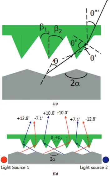
Fig. 2. (Color online) (a) Schematics of a directional backlight. (b) A large inclined angle of viewing cone was emitted from a micro-grooved lightguide. An asymmetric focusing foil was then utilized to redirect light to the eyes.
the right eyes was estimated around 65 mm. The viewer’s left and right eyes were located around⫺10° and 10° to the normal viewing direction, respectively. Mobile applications are the first target application due to the ease of prediction of the viewer’s position without using head tracking systems. Two sets of light sources were switched on sequentially to emit light to the left and the right eyes, respectively. In order to focus the light by different indicated viewing angles in their respective regions, asymmetrical mi-crogrooves were used to redirect light propagation. A slant of grooves becomes steeper while the other slant is gentler. For example, assuming the vertex angle of a grooved light guide is 165°, the emitted angle of 67.5° from the grooved light guide was obtained by ray tracing. The refractive index of the focusing foil is set to be 1.49. For the middle region of the backlight, 1 ⫽ 2 and ⫽ ⫺10° were assumed. As a result,
1⫽ 2⫽ 30° can be obtained according to Eq. (4). In
consideration of the ease of fabrication, 60° of the top angles of asymmetrical grooves remain constant. Nevertheless, the emitted angle of the directional backlight will be shifted due to the rotation of the groove’s slant by a factor of 2. Therefore, in order to satisfy the defined angles ⫺7.1° and ⫺12.8° for the left-handed and the right-handed regions,共1,2兲 are
designed to be共31.5°, 28.5°兲 and 共28.5°, 31.5°兲 due to the shift of the emitted angle of approximately 3°. In other words, from the left-handed to the right-handed regions, the symmetric axis of grooves rotates from 1.5° to⫺1.5° in the gradient. When the display is scaled up, the shift of the emitted angle of the directional backlight and the rotation of the symmet-ric axis of grooves become larger from the central to the edge regions. Furthermore, as in the example we demonstrated, the top angle of the focusing foil needs
to be redesigned and optimized for different viewing distances.
3. Numerical Results and Measurement
In fabrication of the grooved light guide, micro-grooves of a vertex angle of 165° at a groove pitch of 100m were directly cut into the mold by diamond turning. Injection molding was then utilized to fabri-cate the light guide. Additionally, a focusing foil of 60° vertex at a groove pitch of 30m was micromach-ined. The pitch ratio of a grooved light guide to a focusing foil was designed to be less than 3, so that the moiré phenomenon caused by the overlapping of periodic structures could be suppressed and invisible to human eyes. Using white light LEDs with light bars as side-illuminated light sources, angular distri-butions of emitting light from the backlight module were measured by EZcontrast 160. Using backlight brightness intensity of 2100 cd兾m2, Figs. 4(a) and
4(b) depict the measured angular distributions of a directional backlight with a LC panel by sequentially switching the left- and right-side LEDs, plotted as a function of azimuth angle⬘ and inclination angle ⬘.
Fig. 3. (Color online) Schematic of the observer’s relative position and the viewing angle to the display. A backlight of size 35 mm (l) ⫻ 28 mm (w) was placed at a viewing distance of 185 mm. The observer’s left and right eyes are located around⫺10° and 10° to the normal viewing direction.
Fig. 4. (Color online) Using backlight brightness intensity of 2100 cd兾m2, angular distributions of the backlight module with a LC
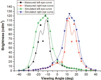
The azimuthal angle defined the rotation of the de-tecting plane of inclination ranges from 0° to 360°. In contrast, the inclination angle defined the radial po-sition of the detecting plane, ranges from 0° to 80°. According to the measurement of Fig. 4(a), most of the light was distributed between the inclination an-gle of⫺30° and 0° when left-side LEDs were switched on. For the⬘ ⫽ 90° cross section shown in Fig. 5, the curves depict the dependence of luminance on differ-ent viewing angles of simulation and measuremdiffer-ent, respectively. The measured curve closely agrees with the simulated curve. However, some issues need to be further considered. Ideally, when left-side LEDs are switched on, only the left eye can observe the image. Practically, after propagating in the light guide, some rays are reflected by the end surface of the light guide, thus, causing cross talk to the other eye.7The
measured luminous intensity is 109 cd兾m2at a view-ing angle of⫺10° (left eye) while 7 cd兾m2at viewing
angle of 10° (right eye), thus resulted in a cross talk of approximately 6%.
4. Discussion
For conventional 3D displays, the viewer is usually limited to some special viewing positions. Inconve-nient feelings hinder our natural vision. From the angular measurement shown in Fig. 5, when our left eye is located at a viewing angle between⫺7.5° and ⫺20° while our right eye is at a viewing angle be-tween 7.5° and 20°, cross talk is less than 10%, which is the minimum criterion to produce stereoscopic im-age perception in our brains.8 The position of the
viewer can be moved within the range of a viewing angle between⫺7.5° and ⫺20°. Therefore, the view-ing distance can be adjusted to within 90 and 250 mm. In addition, cross talk was caused by the reflected rays at the end surface of the light guide. Cross talk can be further improved by increasing light utilization efficiency. If light is fully utilized, there is no light reflecting, thus reducing cross talk.
Besides, by reducing the thickness of the grooved light guide from 1 to 0.8 mm the light utilization efficiency can be further enhanced by 20% because of the increasing opportunities of light hitting on the grooves of the light guide.
Additionally, a fast-switching LC panel is essential to sequentially obtain images in our left and right eyes. If the two field sequential images are displayed with the frame frequency faster than 60 Hz, the flicker is undistinguishable by human eyes. In this case sequentially switching two images, the response time of the LCD needs to be less than 8 ms. A 90° twisted nematic LC panel of an ultrathin cell gap 共2 m兲 was therefore fabricated to achieve a fast re-sponse time. As shown in Fig. 6, the rise and fall times of the LCD are defined as the duration between the 10% and the 90% transmittance. Rise and fall times were measured to be 4.7 and 2.4 ms, respec-tively. Total response time, which is the sum of rise and fall times, can reach 7.1 ms. In addition, to avoid cross talk while refreshing the images of the previous frame, a black image is hence inserted between the left and the right eye image by inputting a black image on the LC panel or switching off the backlight. The former approach needs doubling the frequency of the LC panel. The latter approach, which is the so-called blinking backlight, was used because it made less demands on LC response time. The photographs of a directional backlight with a LCD panel are dem-onstrated in Fig. 7. By switching on light source 1, an image on the LCD is clearly visible at the left eye’s position. At the same time, an image is hardly visible at the right eye’s position. Therefore, it is confirmed that the directional backlight can meet the required properties of time-multiplexed 3D displays.
Furthermore, 2D–3D compatibility is provided by switching on two sets of light sources simultaneously or sequentially, respectively. Two-dimensional image perception is achieved when there is no binocular disparity while simultaneously observing the same image. In contrast, 3D image perception is obtained
Fig. 5. (Color online) For the= ⫽ 90° cross section, the simulated and measured brightness intensity dependences on viewing an-gles.
Fig. 6. (Color online) Rising and falling times measured as the duration between 10% and 90% transmittance.
by combining sequentially switching images in our brain.
5. Conclusion
A directional backlight with a fast switching LCD was designed and fabricated to realize a 3D mobile display. A grooved light guide in combination with an
asymmetric focusing foil was utilized to redirect light to our eyes. The groove structures of the focusing foil with rotation from ⫺1.5° and 1.5° in the gradient were designed to simplify double-sided prism struc-tures, thus avoiding the boundary angle shifted from the normal viewing. Additionally, the pitch ratio of the grooved light guide to the focusing foil is less than 3 to suppress the moiré phenomenon. The measured cross talk of the backlight module with a LC panel is less than 6%. In addition, the blinking backlight was applied on the module to reduce the cross talk while refreshing the image. The response time of the LC can reach 7.1 ms, so that the two field sequential images are displayed without the flicker. The photo-graphs of the directional backlight with a LCD panel are also included to demonstrate the functioning of the devices. By switching on light source 1, an image on the LCD is clearly visible at the left eye’s position while hardly visible at the right eye’s position. Hence, the directional backlight is confirmed to meet the required properties of time-multiplexed 3D displays. Furthermore, the proposed autostereoscopic display module provides 2D–3D compatibility without de-grading display resolution and efficiency in switching mode.
This work was partially supported by National Sci-ence Council, the Republic of China under contract NSC92-2215-E009-053, and AU Optronics Corpora-tion. We express our appreciation to Hugo Cornelissen, Philips Research Laboratories; Jim-Min Chang, Aaron Hu, and Vincent Yang, AU Optronics Corporation, for valuable discussions and technical support.
References
1. P. St-Hilaire, S. A. Benton, M. Lucente, J. D. Sutter, and W. J. Plesniak, “Advances in holographic video,” in Practical
Holog-raphy VII: Imaging and Materials, Proc. SPIE 1914, 188 –196
(1993).
2. P. Soltan, J. A. Trias, W. J. Dahlke, R. V. Belfatto, and F. Sanzone, “Laser-based 3D volumetric display system,” U.S. patent 5,854,613 (29 December 1998).
3. I. Sexton, “Parallax barrier 3-D TV,” in Three-Dimensional
Vi-sualization and Display Technologies, Proc. SPIE 1083, 84 –92
(1989).
4. H. Morishama, H. Nose, N. Taniguchi, K. Inoguchi, and S. Matsumura, “An eyeglass-free rear-cross-lenticular 3D dis-play,” in Society for Information Display (SID) International
Symposium Digest (Society for Information Display, 1998),
pp. 923–926.
5. A. R. L. Travis and S. R. Lang, “The design and evaluation of a CRT-based autostereoscopic display,” in Proceedings of Society
Information Display (SID) (Society for Information Display,
1991), Vol. 32, pp. 279 –282.
6. T. Sasagawa, A. Yuuki, S. Tahata, O. Murakami, and K. Oda, “Dual directional backlight for stereoscopic LCD,” in Society for
Information Display (SID) International Symposium Digest
(So-ciety for Information Display, 2003), pp. 399 – 402.
7. Y. Yeh and L. Silverstein, “Human factors for stereoscopic color displays,” Society for Information Display (SID) International
Symposium Digest (Society for Information Display, 1991), pp.
826 – 829.
8. A. Lit, “The magnitude of the Pulfrich stereo-phenomenon as a function of binocular differences of intensity at various levels of illumination,” Am. J. Psychology, 62, 159 –165 (1949). Fig. 7. (Color online) Demonstrated photographs of a directional
backlight with a LCD panel at the positions of (a) left and (b) right eyes.