Contributed Paper
Manuscript received July 29, 2004 0098 3063/04/$20.00 © 2004 IEEE
An Efficient Architecture for JPEG2000 Coprocessor
Bing-Fei Wu and Chung-Fu Lin
Abstract — JPEG2000 is a new international standard for
still image compression. It provides various functions in one single coding stream and the better compression quality than the traditional JPEG, especially in the high compression ratio. However, the heavy computation and large internal memory requirement still restrict the consumer electronics applications. In this paper, we propose a QCB (quad code block)-based DWT method to achieve the higher parallelism than the traditional DWT approach of JPEG2000 coding process. Based on the QCB-based DWT engine, three code blocks can be completely generated after every fixed time slice recursively. Thus, the DWT and EBCOT processors can process simultaneously and the high computational EBCOT then has the higher parallelism of the JPEG2000 encoding system. By changing the output timing of the DWT process and parallelizing with EBCOT, the internal tile memory size can be reduced by a factor of 4. The memory access cycles between the internal tile memory and the code block memory also decrease with the smooth encoding flow. 1
Index Terms — JPEG2000, DWT, EBCOT, code block,
quad code block.
I. INTRODUCTION
JPEG2000 provides higher quality and more functions than traditional JPEG. Moreover, JPEG2000 takes various functions (i.e. lossless, lossy, progressive, error resilience, ROI etc.) in one single coding stream and has an extensive set of features for diverse imagery systems [1-3]. This superior compression standard can be applied to many consumer electronics applications, such as high-quality digital cameras, surveillance systems, personal mobile devices, and medical images etc. In general, the main coding stream has to be performed by DWT, EBCOT, and MQ blocks, which can be regarded as the core algorithms of JPEG2000 standard. That is, after the process of these three coding blocks, the main coding stream can be generated to produce a JPEG2000 file. However, the complex encoding process requires much execution time. In the hardware implementation, the issues of high computation blocks and effective integration demand still restrict the wide applications of JPEG2000.
Considering these three core blocks individually, the performance of DWT, EBCOT, and MQ processors are intensive with its throughput and memory requirement. Many studies are devoted to the optimization of the specific component. Generally, DWT needs a tile buffer to perform the subband transform [4]. Then, EBCOT divides each subband into several code blocks and performs the bit-plane coding
1 All authors are with the Electrical and Control Engineering Department,
National Chiao Tung University (e-mail: {bwu, cflin}@cssp.cn.nctu.edu.tw).
algorithm [5-7]. The MQ coder is a lossless compression, followed by EBCOT to generate the main compression data [8].
Although the dedicated components can be optimized individually, the overall encoding system may suffer performance degradations and need more hardware resources since different components require different I/O bandwidth and buffers [9,10]. In this paper, we propose a QCB-based DWT engine to ease the performance degradation of integration. Based on the changed output timing of the DWT process, three code blocks are iteratively generated every fixed execution time slice and the DWT and EBCOT processes can reach higher parallelism than the traditional DWT method. Moreover, the overall performance can preserve the high performance of the individual component and the internal memory size is also reduced.
The paper is organized as follows. In Section II, the brief concept and the timing analysis of the basic JPEG2000 blocks is addressed. In Section III, the proposed QCB-based DWT method will be discussed and the architecture of the JPEG2000 coprocessor are emphasized. In Section IV, the overall performance is evaluated under the different bus architectures. In Section V, we compare the proposed architecture design with other related works [9,10]. Finally, a brief summary is given in Section VI.
II. JPEG2000BASIC BLOCKS
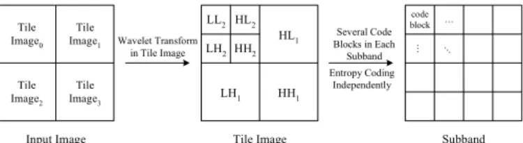
The basic blocks of JPEG2000 algorithm can be described in Fig.1. During the coding process, an image is split into several rectangular tiles. Then each tile can be coded independently. In general, the entire tile image needs to be buffered to perform the subband transformation. That is, the 2-D 2-DWT decomposes a tile image into LL, LH, HL, and HH subbands. The LL band can be decomposed into next resolution recursively. After the wavelet transform, coefficients in each subband are partitioned into several code blocks and performed independently by the EC (Entropy Coder) algorithm. The EC process carries out EBCOT and MQ algorithms. First, the EBCOT processes each code block bit-plane by bit-plane, and generates the context-based information. Then, the context data outputs are lossless coded by MQ coder to generate the main coding stream.
Input Image Tile Image0 Tile Image1 Tile Image2 Tile Image3 Tile Image Wavelet Transform in Tile Image Several Code Blocks in Each Subband Subband HL1 HH1 LH1 HL2 HH2 LH2 LL2 Entropy Coding Independently code block … … …
Several studies have been focused on the dedicated hardware design for the individual components of JPEG2000 [9,10]. However, the different coding flows and memory requirement are still crucial factors of integrating of overall JPEG2000 architecture. In this paper, we focus on the overall performance and memory reduction of JPEG2000 coprocessor architecture.
To achieve the high throughput of the overall JPEG2000 process, the parallel process between DWT and EBCOT is needed. Based on the pipelined DWT architecture [4,9,11,12], the throughput of DWT is dominated by the number of memory accesses and hardware resources. In the single DWT-processor design, it needs N2 clock cycles to read row images
for an N x N image to perform row-wise transform, and HL and HH bands are then generated with additional N2/2 clock
cycles. After extra N2/2 clock cycles, the LH and LL bands are available and the LL band can be decomposed into next resolution recursively. The detailed analysis is listed in TABLE I. Since the dyadic decomposition of DWT, the output numbers of code blocks in each subband decrease dependent on the higher DWT resolution.
TABLEI
THE RELATION OF DWT OUTPUT TIMING AND OUTPUT NUMBER OF CODE
BLOCKS (IMAGE SIZE=N X N, CODE BLOCK SIZE=N/8 X N/8, MEMORY
PORT: A READ PORT AND A WRITE PORT,3 LEVEL DECOMPOSITION). Clock cycle N+ 2 N+ 2/2 N+ 2/2 N+ 2/4 N+ 2/8 N+ 2/8 N2+ /16 N2+ /32 N2+ /32
DWT decompositi
on
Resolution 1 Resolution 2 Resolution 3 Number of code blocks produced row-data proce ssing 32 16 Row-data proce ssing 8 4 row-data proce ssing 2 2
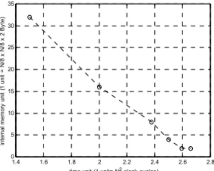
To parallelize with the DWT and EBCOT processors, internal memory and multiple EBCOTs are used to process the output code blocks. As listed in TABLE I., there should be 32 code-block size memories to buffer the HL and HH subband coefficients after 3/2N2 clock cycles, but the memory
requirement decreases as the execution time increasing due to the dyadic property of DWT decomposition, shown in Fig.2.
1.4 1.6 1.8 2 2.2 2.4 2.6 2.8 0 5 10 15 20 25 30 35
time unit (1 unit= N2 clock cycles)
in te rn al m e m ory uni t ( 1 u ni t = N /8 x N /8 x 2 B y te )
Fig. 2. Memory requirements v.s. execution time (i.e. image size= NxN, 3 DWT decomposition).
Moreover, several EBCOT architectures are proposed to speed up the high computational bit-plane coding algorithm
[5-7]. These speed-up methods can be classified into three main ways: sample skip, pass parallel, and bit-plane parallel processes. The architectural models of these methods are listed in TABLE II. Considering the hardware cost and flexibility, we choose the pass parallel architecture in the overall encoding system [6]. Based on the architectural model, it requires 8 EBCOT processors to carry out 32 code blocks within N2/2 clock cycles (i.e. assume 8 coding bit-plane,
L=N/8, 3 level decomposition). Thus, the large internal memory requirement and hardware cost cause EBCOT become the bottleneck of overall JPEG2000 encoding flow.
TABLEII
THE ARCHITECTURAL MODEL OF DIFFERENT METHODS
(L: THE WIDTH OF CODE BLOCK).
Number of Processors Architecture Processing Time Average EBCOT
processor MQ processor Sample Skip [5] 1.3 x n x L2 1 1 Pass parallel [6] n x L2 1 3 Bit-plane parallel [7] (1+δ ) x L2 10 5
III. PROPOSED JPEG2000ARCHITECTURE
A. QCB-based Architecture for JPEG2000 Coprocessor
To reduce the memory size and hardware cost, we propose a novel method for DWT process --- QCB (quad code block)- based DWT. The basic idea of the QCB- based DWT is to produce complete code blocks as soon as possible and performed by the EBCOT processor directly.
Based on the approach, a tile image is divided into several QCB blocks in advance of the DWT procedure, as shown in Fig.3. The QCB block0 then carries out the QCB-DWT
process and generates four code blocks --- three for EBCOT encoding, and one for the next DWT decomposition, recursively. Based on the pipelined DWT architecture, the QCB-DWT throughput is approximately N2/8, dominated by
the number of memory accesses (i.e. 2 x N /4 x N /4, twice memory access for row and column processing). Thus, the QCB-DWT can recursively generate three complete code blocks for EBCOT processors every N2/8 clock cycles.
LL band
QCB block0
DWT transform
3 code blocks in HL, LH, HH subband and 1 code block in LL subband
HL band LH band HH band Contributed from QCB block0 QCB block1 QCB block2 QCB block3 QCB block4 QCB block5 QCB block6 QCB block7 QCB block8 QCB block9 QCB block10 QCB block11 QCB block12 QCB block13 QCB block14 QCB block15 QCB block0 Tile Image N 4 N 8 N … … … … … … … … … … … …
Fig. 3. The QCB-DWT process in a tile image (Assume tile size= NxN, code block size= N/8 x N/8).
Under the same assumptions of 8 coding bit-planes and pass-parallel architecture of EBCOT, we only need three
EBCOT processors to encode these three code blocks independently within N2/8 clock cycles, and achieve the same
throughput of DWT. Also, the code block of LL band can be decomposed into next resolution. Based on the parallel processing, the ping-pong buffer CBM is required for DWT and EBCOT switching. The overall JPEG2000 coprocessor architecture is shown in Fig.4 and the memory requirements are listed in TABLE III. Based on the QCB-based DWT engine, the DWT and EBCOT processes can achieve higher parallelism. Thus, the internal tile memory size can be reduced by a factor of 4, i.e. only LL1 subband is needed to buffer. The
hardware cost of EC is also decreased.
CBM0 -- ping pong buffer CBM1 -- ping pong buffer CBM2 -- ping pong buffer QCB-DWT Controller Main coding stream buffer LL LH HL HH Tile image Rate-Distortion controller File formatting EBCOT0 MQ0 EBCOT1 MQ1 EBCOT2 MQ2 EC2 EC1 EC0
Fig. 4. Architecture of JPEG2000 Coprocessor. TABLEIII
THE MEMORY REQUIREMENT OF THE PROPOSED ARCHITECTURE.
Assume: tile size= 256x256, code block size= 32x32 Memory Type Memory Requirement
(K Bytes) Tile Memory
(QCB-DWT) 1/4 x (256x256x16) = 32 Code block Memory
(CBM0 ~ CBM3) 2x3x32x32x16 = 12
B. QCB-based DWT Method
The basic idea of QCB-DWT is to divide a tile image into several QCB size images to perform the DWT process. Thus, the EBCOT can execute the bit-plane coding immediately after three code blocks are produced. Since the code block size is determined by the user or system demand (i.e. 32x32 or 64x64 in general), it is reasonable to define the QCB block size before actually performing the QCB-DWT procedure. That is, the QCB block size is double width and height of one code block size.
However, the QCB-DWT breaks the data path of each row and column image, some modifications should be applied to preserve the primitive algorithms. The lifting-based DWT algorithm is suitable for pipeline design method [4,11,12]. Since the data path is broken due to the boundary between two neighbor QCB blocks, it is necessary to store the pipeline registers for each QCB block boundaries to preserve the original data path by using internal or external memories.
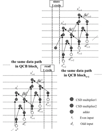
Considering the fast pipeline data path proposed in [12], there are 2 additional cycles--- “read” and “store” cycles which are needed to preserve the original data path in 5/3 filters, as shown in Fig.5. A quantitative analysis of additional memory access cycles are formulated in Eq(1)- Eq(3). The penalty of memory
accesses in 5/3 filters and 9/7 filters are 2 and 5, since there are only one lifting step in 5/3 case but two steps in 9/7 filters. The detailed analyses of memory access increasing rate are listed in TABLE IV. With a little increasing of memory accesses than traditional DWT, QCB-DWT provides higher parallelism with EBCOT and less memory requirement in the overall JPEG2000 encoding system. read 1 cycle 0 i s 0 i d 0 1 + i s 0 1 + i d 0 2 + i s 1 i s 1 i d β 1 1 + i s 1 1 + i d β 0 2 + i s 0 2 + i d 0 3 + i s 0 3 + i d 1 2 + i s 1 2 + i d β 1 3 + i s 1 3 + i d β store 1 cycle
the same data path in QCB blocki
the same data path in QCB blocki+1 …… …… adder CSD multiplier1 CSD multiplier2 i s i d Even input Odd input …… ……
Fig. 5. Additional cycles to preserve the same data path between different QCB blocks.
Assume image size= NxN,
access memory original of Number cycles Additional rate increasing access Memory = (1)
∑
= × = J i 1 * registers) pipeline restoring for {(penalty 2 cycles Additional )} resolution in boundary of (number * ) resolution of (height i i (2)∑
= − × = J i i N 1 2 1 4 1 2 access memory original of Number (3) TABLEIVTHE INCREASING RATE OF MEMORY ACCESS FOR
DIFFERENT DWT DECOMPOSITION LEVELS.
Memory access increasing rate (Tile size= 256x256, code block size= 32x32) Filters
1 level 2 level 3 level 4 level 5 level 5/3 2.3 % 2.1 % 2.2 % 2.3 % 2.3 % 9/7 5.9 % 5.5 % 5.6 % 5.7 % 5.8 %
C. JPEG2000 Coprocessor Design
Considering the hardware implementation of JPEG2000 coprocessor shown in Fig.4, one needs to define the basic handshaking for each component to control the DWT, CBM and EC components correctly. Since a tile image is divided into several QCB images, we use “Tile_INIT” and “TILE_INIT_ACK” signals to complete the tile initialization and use the “QCB_INIT” and “QCB_INIT_ACK” signals to achieve the QCB initialization. As shown in Fig.6, each component can be initialized via the proper configuration data. In general cases, several QCB processes are carried out in a tile procedure. The “QCB_Done” and “QCB_Done_ACK” signals indicate the end of each QCB process and can be used to synchronize the QCB process.
Tile_En (I) Tile_INIT (I) Tile_INIT_DATA (I) Tile_INIT_ACK (O) QCB_INIT_DATA (I) QCB_INIT (I) QCB_INIT_ACK (O) QCB_Done (O) QCB_Done_ACK (I)
Repeat this process
Processing ... Reset (I)
Data
Data
Fig. 6. The basic handshaking of each component.
Based on the basic handshaking, the main controller is designed to control the overall data flow. As shown in Fig.7, the “Tile_setteing” and “QCB_setting” states can be synchronized by checking the “Tile_INIT_ACK” and “QCB_INIT_ACK” signals from each component. Similarly, the “QCB_process” state can be synchronized through the inspection of each “QCB_Done” signals. The detailed descriptions of each state are depicted in TABLE V.
idle Done RSTn = 0 QCB_finished INIT_controller Tile_setting QCB_process QCB_setting All image finished? Reset_components
Until all component Tile_INIT_ACK =‘ 1’
Until all component QCB_Done =‘ 1’
Several QCB-processes in a tile
Next QCB block Next tile
image
Until all component QCB_INIT_ACK =‘ 1’
Fig. 7. Finite state machine of the main controller.
TABLEV
DESCRIPTION OF THE MAIN FINITE STATE MACHINE.
State Description Idle Coprocessor in the idle state
Reset_components Reset all components (contained: DWT, CBM, EC) INIT_controller Calculate the initial data of each component
Tile_setting Initialization for tile process QCB_setting Initialization for QCB process
QCB_process DWT, CBM, EC process the data concurrently QCB_finished Go to the next QCB process, or process the new tile
image, or finish the overall coding process Done Coprocessor done
Finally, since the input image size is different, the initial data for each component have to be calculated for the various image size. TABLE VI describes the algorithm to calculate the initial data of each component. Since the tile memory size may be restricted by the hardware cost, the “Tile_sizeY” and “Tile_sizeX” are set to programmable variables. The output parameters are then used to initialize the DWT, CBM, and EC components. The algorithm can be realized by the software or hardware optimized through the look-up table under the specific parameters.
TABLEVI
THE QCB INITIALIZATION ALGORITHM.
/* Controller initialization */
/* Calculate the number of tiles in the input image */ Input:
//input image size
Image_sizeY, Image_sizeX,
//user-defined tile size (i.e.128x128 or 256x256) Tile_sizeY, Tile_sizeX,
Output:
//number of tiles in an image Tile_numberY, Tile_number_X, /* Declare */ Tile_numY =0; Tile_numX =0; Ts_X=0; Ts_Y=0; /* Calculate */
//Calculate the X-axis tile number in an image while (Ts_X=< Image_sizeX){
Ts_X=Ts_X + Tile_sizeX; Tile_numX ++;
}
//Calculate the Y-axis tile number in an image while (Ts_Y=< Image_sizeY){
Ts_Y=Ts_Y + Tile_sizeY; Tile_numY ++; } /* output */ Tile_numberX= Tile_numX; Tile_numberY= Tile_numY;
TABLEVI
THE QCB INITIALIZATION ALGORITHM (CONT’D).
/* Controller initialization */
/* Calculate the QCB initialization data for each component */
Input:
Image_sizeY, Image_sizeX, // input image size Tile_sizeY, Tile_sizeX, // user-defined tile size
Tile_index_Y,Tile_index_X, // input the tile index number //of an image Output:
CB_sizeY, CB_sizeX, QCB_sizeY, QCB_sizeX, Dwt_level /* Declare */
Dwt_num=0;
CBS=32; //code block size is 32x32 ist_Y=Tile_sizeY; //default size: tile size ist_X=Tile_sizeX; //default size: tile size /* Calculate */
//calculate the corner size in the tile image if (Image_sizeY < Tile_sizeY*Tile_index_Y)
ist_Y= Image_sizeY – Tile_sizeY*(Tile_index_Y-1); if (Image_sizeX < Tile_sizeX*Tile_index_X)
ist_X= Image_sizeX - Tile_sizeX*(Tile_index_X-1); //LL band size must less then code block size
while (ist_X>=CBS or ist_Y>=CBS) { ist_Y=ist_Y>>1; ist_X=ist_X>>1; Dwt_num++; } /* output */
Dwt_level=Dwt_num ; // Number of DWT decomposition CB_Y=ist_Y; // Code block height
CB_X=ist_X; // Code block width QCB_Y=ist_Y>>1; // Quad Code block height QCB_X=ist_X>>1; // Quad Code block width
IV. OVERALL SYSTEM PERFORMANCE
Based on the QCB-based DWT engine, the proposed JPEG2000 coprocessor achieves higher parallelism and requires less hardware resources than the traditional DWT method. However, the overall performance could be still restricted by the I/O bandwidth. Thus, the overall hardware cost can be optimized for the different bus architectures. In the bus issue, we consider the split bus and single bus architectures. In the split bus, since there are separate I/O ports, the QCB-DWT and EC can execute concurrently by using CBM (ping-pong buffer) to execute each QCB process, as shown in Fig.8. Since every time slice delay is determined by the QCB-DWT throughput and the coding bit plane number processed by EBCOT, it is reasonable to design both components with the same throughput. Based on the pass-parallel [6] architecture of EBCOT and the single
DWT-processor design, three EBCOT DWT-processors can reach to the QCB-DWT throughput under the 8-coding bit plane assumption.
In the single bus architecture, the bus timing is shown in Fig.5. Since the QCB-DWT and EC use the same I/O bus, the two components can be optimized individually to increase the overall throughput and CBM can be reduced to the single buffer. However, since the QCB-DWT and EC cannot process simultaneously under the single bus condition, the main advantage of the QCB-based method is the less internal tile memory requirement. QCB_DWT QCB_DWT QCB_DWT QCB_DWT QCB_DWT QCB_DWT EC EC EC EC Input : Output : CBM CBM
( DWT_QCB_Done = ‘‘‘‘ 1’’’’ & EC_QCB_Done = ‘‘‘‘ 1’’’’ )
CBM CBM
CBM CBM
EC
……
Fig. 8. The I/O timing of the spilt bus architecture.
QCB_DWT QCB_DWT QCB_DWT EC EC Input : Output : CBM CBM ( DWT_QCB_Done =‘‘‘‘ 1’’’’ ) CBM CBM CBM EC CBM ( EC_QCB_Done = ‘‘‘‘ 1’’’’ ) ……
Fig. 9. The I/O timing of the single bus architecture.
Moreover, we evaluate the overall performance of JPEG2000 coprocessor in the split bus architecture in TABLE VII. Several 256x256 size images are chosen as the test benches to assess the performance of the proposed architecture performing 3-level DWT decomposition and EC process (i.e. code block size is 32x32). The pipelined QCB-DWT and three pass-parallel EC architectures are applied to the coprocessor. TABLE VII lists the detailed clock cycles of each component and overall performance. Under the real test pattern, the clock cycle of EBCOT in each QCB process is determined by the maximal coding bit plane number of the three code blocks. Since the coding bit plane number is not larger than eight, the QCB process is restricted by the throughput of QCB-based DWT (i.e. 66x66x2=8712, (64+2) for the worst case of 5/3 filters). In comparison of the QCB-based and the traditional DWT based JPEG2000 coprocessor architecture, the proposed architecture needs less clock cycles to process the same testing image since it has the higher parallelism between the DWT and EC processes.
TABLEVII
THE PERFORMANCE OF THE QCB-BASED JPEG2000 COPROCESSOR.
Average 64 code block Overall performance (clock cycle) Testing image QCB process of 5/3 DWT (clock cycle) QCB process (clock cycle) Number of coding bit plane QCB-based DWT method Traditional DWT method Lenna256 8712 7168 6.51 207024 256000 Baboon256 8712 6981.81 6.73 207024 251904 Pepper256 8712 7028.36 6.54 208048 252920 Airplane256 8712 6888.72 6.17 207024 249840 V. COMPARISON
The traditional DWT process requires a large tile buffer to perform the wavelet transformation and the parallelism between DWT and EBCOT processors is also decreased. Based on the proposed QCB-DWT engine, the original tile image is divided into several QCB blocks in advance of the DWT process. By recursively generating three code blocks, it gains higher parallelism in DWT and EBCOT processes and increase the overall throughput. In comparison with related work for JPEG2000 coprocessor based on the traditional DWT method [9,10], the proposed architecture requires less internal tile memory by a factor of 4 through the QCB-based DWT engine. As shown in TABLE VIII, the proposed architecture requires only 1/4 tile memory to save the LL band coefficients and the three EC processors can execute the bit plane coding algorithm after the first QCB process is finished. The high parallelism between DWT and EC increases the overall performance and the efficient data-reuse also decreases the number of internal memory access. Finally, the QCB-based architecture can support larger tile size without degrading the throughput since the DWT and EBCOT processors execute concurrently in each QCB process.
TABLEVIII
COMPARISONS OF THE MEMORY REQUIREMENT AND THE NUMBER OF EC
PAIRS (ASSUME TILE SIZE=128X128, FOR COMPARISONS).
JPEG2000 coprocessor Hardware cost
AMPHION [10] ANDRA et.al. [9] architecture Proposed Tile memory 4096x16x4= 32 128x128x16= 32 1/4x128x128x16 = 8 Memory Requirem ent
(K bytes) Code block memory 1024x16x6= 12 32x8x64x3= 6
2x3x32x32x16= 12
Entropy Coder pairs 3 3 3
VI. CONCLUSION
In this paper, we propose a QCB-based DWT method to raise the parallelism of JPEG2000 encoding flow and to decrease the internal memory requirement. In the hardware implementation, the performance degradation and hardware cost are two main issues of the integration of JPEG2000 coprocessor. Based on the QCB-DWT engine, three code blocks can be produced in each fixed time slice, the Entropy Coder architecture then can be designed in accordance with the QCB-DWT throughput to achieve the high parallelism of
JPEG2000 coding process. The proposed architecture not only raises the overall throughput but also decreases the on-chip memory requirement by a factor of 4. The proposed JPEG2000 coprocessor can be optimized under different bus architecture. Thus, the proposed architecture can be applied to the JPEG2000-based imagery system for many image applications.
REFERENCES
[1] ISO/IEC. ISO/IEC 15444-1. Information technology – JPEG 2000 image coding system, 2000.
[2] F. Frescura, M. Giorni, C. Feci, and S. Cacopardi, “JPEG2000 and MJPEG2000 transmission in 802.11 wireless local area networks,” IEEE Transactions on Consumer Electronics, Vol. 49, No. 4, pp. 861– 871, Nov, 2003.
[3] A. Signoroni, F. Lazzaroni, and R. Leonardi, “Exploitation and extension of the region-of-interest coding functionalities in JPEG2000,” IEEE Transactions on Consumer Electronics, Vol. 49, No. 4, pp. 818– 823, Nov. 2003.
[4] K. Andra, C. Chakrabati, and T. Acharya, “A VLSI Architecture for Lifting-Based Forward and Inverse Wavelet Transform,” IEEE TRANSACTIONS ON SIGNAL PROCESSING, VOL.50, NO.4, pp. 966-977, APRIL 2002.
[5] C.J. Lian, K.F. Chen, H.H. Chen, and L.G. Chen, “Analysis and Architecture Design of Block-Coding Engine for EBCOT in JPEG2000, ” IEEE TRANSACTIONS ON CIRCUIT And SYSTEMS FOR VEDIO TECHNOLOGY, VOL.13, NO.3, pp. 219-230, MARCH 2003. [6] J.S. Chiang, Y.S Lin, and C.Y. Hsieh, “Efficient Pass-Parallel
Architecture For EBCOT in JPEG2000, ” THE 2002 IEEE International Symposium on Circuits and Systems, VOL. 1, pp. 773-776, MAY 2002. [7] H.C. Fang, T.C Wang, C.J. Lian, T.H. Chang, and L.G. Chen, “High
Speed Memory Efficient EBCOT Architecture for JPEG2000,” THE 2003 IEEE International Symposium on Circuits and Systems, Vol. 2, Thailand, pp. 736-739, MAY 2003.
[8] K.K. Ong, W.H. Chang, Y.C. Tseng, Y.S. Lee, and C.Y. Lee, “A high throughput low cost context-based adaptive arithmetic codec for multiple standards,” The 2002 IEEE International Symposium on Image Processing, VOL.1, pp. 872-875, Sept. 2002
[9] K. Andra, C. Chakrabati, and T. Acharya, “A High-Performance JPEG2000 Architecture,” IEEE TRANSACTIONS ON CIRCUIT And SYSTEMS FOR VEDIO TECHNOLOGY, VOL.13, NO.3, pp. 209-218, MARCH 2003.
[10] AMPHION Products ---CS6510 JPEG2000 Encoder [Online].Available: http://www.amphion.com/cs6510.html
[11] J.M. Jou, Y.H. Shiau, and C.C. Liu, “Efficient VLSI Architectures for the Biorthogonal Wavelet Transform by Filter Bank and Lifting Scheme,” The 2001 IEEE International Symposium on Circuits and Systems, vol. 2, pp. 529 –532, 2001.
[12] B.F Wu and C.F. Lin, “A Rescheduling and Fast Pipeline VLSI Architecture for Lifting-based Discrete Wavelet Transform,” The 2003 IEEE International Symposium on Circuits and Systems, VOL. 2, pp. 732–735, May, 2003.
Bing-Fei Wu (S’89-M’92-SM’02) was born in Taipei, Taiwan in 1959. He received the B.S. and M.S. degrees in control engineering from National Chiao Tung University (NCTU), Hsinchu, Taiwan, in 1981 and 1983, respectively, and the Ph.D. degree in electrical engineering from the University of Southern California, Los Angeles, in 1992.
From 1983 to 1984, he was with the Institute of Control Engineering, NCTU as an Assistant Researcher. From 1985 to 1988, he was with the Department of Communication Engineering at the same university as a Lecturer. Since 1992,
he has been with the Department of Electrical Engineering and Control Engineering, where he currently is Professor. As an active industry consultant, he was also involved in the chip design and applications of the flash memory controller and 3C consumer electronics in multimedia. The research has been awarded by the Ministry of Education (MOE) as the Best Industry-Academics Research Cooperation in Universities. His research interests include chaotic systems, fractal signal analysis, multimedia coding, wavelet analysis and applications.
Prof. Wu is a Senior Member of IEEE. He also holds the memberships of the Chinese Automatic Control Society, Chinese Institute of Electrical and Electronic Engineers and Chinese Institute of Engineers (CIE). He founded and served as the Chair of the IEEE Systems, Man and Cybernetics Society Taipei Chapter in Taiwan, 2003. He has been the Director of The Research Group of Control Technology of Consumer Electronics in the Automatic Control Section of National Science Council (NSC), Taiwan, from 1999 to 2000. Prof. Wu received the Research Awards from NSC in the years of 1992, 1994, 1996-2000; the Long-Term Dragon Golden Thesis Award sponsored by the Acer Foundation in 2003; the First Prize Award of the We Win (Win by Entrepreneurship and Work with Innovation & Networking) Competition hosted by Industrial Bank of Taiwan in 2003; the Silver Award of Technology
Innovation Competition sponsored by the AdvanTech in 2003; the Third Winner Award in the Hewlett-Packard Information Appliance Competition in 2000; The first Runner-Up Macronix Golden Silicon Award and the Best Originality Award in the 1st and 2nd Semiconductor and Application
Competition sponsored by Macronix International Co., Ltd., in 2001-2002; the Distinguished Engineering Professor Award from CIE in 2002; and the Outstanding Information Technology Elite Award in 2003.
Chung-Fu Lin (S’02) was born in Taipei, Taiwan in 1977. He received the B.S. degree in mechanical engineering from National Central University in 1999 and M.S. degree in mechanical engineering from National Chiao Tung University. He is a Ph.D student in the electrical and control engineering from National Chiao Tung University. He received the Macronix Golden Silicon Honorable Mention in the 3rd
Semiconductor and Application Competition sponsored by Macronix International Co., Ltd., in 2003. His research interests include multimedia application, VLSI design and implementation.