Mingsian R. Bai
Yujeng Lin
Department of Mechanical Engineering, National Chiao-Tung University, 1001 Ta-Hsueh Road, Hsin-Chu 300, Taiwan, Republic of ChinaJian-Da Wu
Department of Vehicle Engineering & Technology, Da-Yeh University, 112 Shan-Jeau Road, Da-Tsuen, Chang-Hwa 515, Taiwan, Republic of ChinaAnalysis and DSP Implementation
of a Broadband Duct ANC System
Using Spatially Feedforward
Structure
The active control technique for broadband attenuation of noise in ducts, using spatially feedforward structure, is investigated from the viewpoints of both acoustic analysis and control engineering. According to the previous work by Munjal and Eriksson [1], there exists an ideal controller for this problem. The ideal controller is a function of the finite source impedance and is thus independent of the boundary conditions. Despite the sim-plicity, the ideal controller cannot be practically implemented due to the difficulty of calibration of electro-mechanical parameters. To overcome the problem, the controller is implemented via an equivalent formulation modified from the controller originally pro-posed by Roure [2]. The modified controller is implemented on a DSP platform, using a FIR filter, an IIR filter and a hybrid filter. The experimental results showed that the system achieved 17.2 dB maximal attenuation in the frequency band 300⬃600 Hz. Physical insights and design considerations in implementation phase are also discussed in the paper. 关DOI: 10.1115/1.1355031兴
1 Introduction
Active noise control 共ANC兲 techniques have attracted much research attention because they provide numerous advantages over conventional passive methods in attenuating low frequency noises关3兴. In the ANC applications to date, feedforward control has been widely used whenever nonacoustical reference is avail-able关4兴. However, if nonacoustical reference is not available but the order of the system is small, e.g., the headset problem, feed-back control should be a feasible approach关5兴. Feedback control by colocated sensors and actuators results in a passive, positive real and thus minimum phase plant关6,7兴. The phase response of such a system always alternates between ⫾90 deg. Stability is guaranteed because of the passivity关8兴. In practical implementa-tion, however, the positive real共PR兲 property may no longer exist due to in-band transducer dynamics. As a crucial step in the feed-back design, certain phase compensation schemes may be needed to alleviate this nonpositive real problem关9兴.
In the other extreme of high-order systems, conventional feed-back control generally achieves only narrowband attenuation due to spillover effect关7,10兴. In this paper, a more preferable structure, the spatially feedforward structure 共Fig. 1共a兲兲 is exploited for high-order systems, where nonacoustical reference is unavailable and broadband attenuation is desired. It has been demonstrated in Hong and Bernstein’s paper 关7兴 that the spatially feedforward structure suffers less from the spillover problem than the colo-cated feedback structure.
In the spatially feedforward control structure, a measurement sensor is placed near the noise source but far away from the con-trol source. The measurement sensor measures the sound from not only the noise source but also the control source 共the latter is called acoustic feedback path that generally causes undesirable effects兲. From the viewpoint of control theory, the structure per se is not feedforward since nonacoustic disturbance is not accessible. This is hence the reason why we use the term ‘‘spatially feedfor-ward.’’ It shares the same design constraints on performance, sta-bility and robustness as the other classical feedback systems.
For the spatially feedforward structure, Munjal and Eriksson关1兴 derived an ideal ANC controller based on acoustic filter theory. The ideal controller is a function of the finite source impedance only and is thus independent of the upstream and downstream conditions. This paper seeks to provide an in-depth acoustic analysis of an ideal controller for ducts and details of how to implement it. Using electro-mechanical analogy, the ideal control-ler is extended to incorporate the transducer dynamics. However, after several attempts, the ideal controller still cannot be imple-mented due to the errors in calibrating electro-mechanical param-eters. To overcome the difficulty, the controller is implemented
Contributed by the Technical Committee on Vibration and Sound for publication in the JOURNAL OFVIBRATION ANDACOUSTICS. Manuscript received July 1999; revised Oct. 2000. Associate Editor: R. L. Clark.
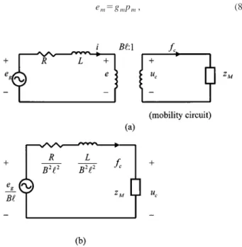
Fig. 1 Spatially feedforward structure „a… schematic of the duct ANC system„b…equivalent circuit
via an equivalent formulation modified from the original control-ler proposed by Roure 关2兴. The modified controller is imple-mented on a DSP platform, using a FIR filter, an IIR filter and a hybrid filter. The experimental results showed that the proposed system achieved broadband attenuation of the noise in a duct. The design considerations in practical implementations are also dis-cussed in the paper.
2 Analysis of the Ideal Controller for Ducts
The spatially feedforward ANC system for a duct and its equivalent circuit are shown in Fig. 1. Based on the concept of acoustic short-circuit, Munjal and Eriksson关1兴 derived an ideal controller capable of achieving global noise cancellation down-stream the control source in a finite-length duct:
Cideal⫽⫺ Zsa
Y0
冉
e⫺ jkl1
1⫺e⫺2 jkli
冊
⫽CE M•CR P, (1) where Zsa is the acoustic impedance of the control source, Y0 ⫽c/S is the characteristic impedance of the duct, c is the soundspeed, S is the cross sectional area of the duct, k is wavenumber, and liis the distance between the upstream measurement micro-phone and the control source. This ideal controller is an infinite-dimensional controller and no modal truncation was made. In Eq.共1兲,
CE M⬅⫺ Zsa
Y0
(2) is a function of the finite impedance Zsawhich depends only on the electro-mechanical constants of the control source. On the other hand,
CR P⬅ e⫺ jkli
1⫺e⫺2 jkli (3)
exhibits an interesting form of a repetitive controller关11兴 which periodically reproduces any finite duration input signal. Its fre-quency response and impulse response both show equally spaced peaks共⌬ f ⫽c/2li, ⌬t⫽2li/c兲. If the system contains no damp-ing, the poles will be on the imaginary axis and the repetitive controller is unstable. These unstable poles are introduced due to acoustic feedback. At the pole frequencies, the controller exerts high gain because the measurement sensor is at the pressure node. In reality, absorption effect of ducts is always present共such as the wooden duct in our case兲 and the wave number k becomes com-plex. The poles of repetitive controller will be in the open left-half space and the controller is stable. However, for lightly damped duct and omni-directional transducers, the controller can be mar-ginally stable and the impulse response can be unacceptably long. To avoid the adverse effect of acoustic feedback, directional trans-ducers or arrays can be used关12,13兴.
From Eq. 共1兲, some interesting features are noted. For a feed-back structure (li⫽0), Cideal→⬁, which implies colocated feed-back control is an impractical approach for global attenuation. Secondly, the controller is applicable to all frequencies and is thus a broadband controller. In particular, the controller produces maximal attenuation at the resonances of the duct field. Third, the ideal controller is independent of the conditions upstream the ref-erence microphone and downstream the control source such as the primary source impedance and radiation impedance. This provides an advantage in practical applications in which a universal, de-tachable ANC module can be developed for various kinds of op-erational conditions. It is also noted that the performance of at-tenuation still depends on boundary conditions, although the form of ideal controller remains unique.
3 Implementation of Practical Controllers
3.1 Method of Electro-mechanical Constants. From Eq.
共1兲, the implementation of the ideal controller requires the
knowl-edge of the control source impedance Zsa. In what follows, Zsa will be expressed explicitly in terms of speaker parameters.
Figure 2共a兲 shows an electro-mechanical equivalent circuit of a moving-coil loudspeaker关14兴. In the figure, egis the open-circuit voltage of the generator; R is the total equivalent resistance of the coil; L is the equivalent inductance of the coil; Bl is the coil constant; uc is the cone velocity; fc is the force produced by the coil; zMis the mechanical mobility. Reflecting all elements, eg, R and L, to the mechanical side yields Fig. 2共b兲. Let ⍀ be the analog frequency. The ‘‘blocked’’ (uc⫽0) force is
fc兩uc⫽0⫽ eg/Bl R B2l2⫹ j⍀ L B2l2 ⫽ egBl R⫹ j⍀L, (4)
whereas the ‘‘free’’ ( fc⫽0) velocity is uc兩fc⫽0⫽ eg Bl zM R B2l2⫹ j⍀ L B2l2⫹zM . (5)
Thus, Zsa can be expressed as Zsa⫽ 1 S2 fc兩uc⫽0 uc兩fc⫽0⫽ 1 S2
冉
1 zM⫹ B2l2 R⫹ j⍀L冊
. (6) As expected, Zsadepends solely on speaker parameters R, L and Bl which can be identified in advance by some existing共but often not trivial兲 procedures, e.g., Bai and Wu 关15兴.In addition to the speaker dynamics, the characteristics of the microphone and the power amplifier must be taken into account such that the input and output of the controller involve only elec-trical voltages. Referring to Fig. 3, the controller to implement is defined as
Cideal⬘ ⬅ es em
, (7)
where em is the output voltage of the measurement microphone and es is the input voltage of the power amplifier. The loading effect in the microphone is negligible because the input imped-ance of the pre-amp is generally very large. Thus the microphone is assumed to have a constant gain gmthat can be obtained from the microphone vendor. Hence,
em⫽gmpm, (8)
Fig. 2 Electro-mechanical analysis of a moving coil speaker „a… equivalent circuit with an ideal transformer„b… circuit re-flected to the mechanical side
where pmis the input acoustic pressure of the microphone. From Eq.共4兲, it can be shown that speaker frequency response function
Gs⬅ ps eg⫽
Bl
S共R⫹ j⍀L兲, (9)
where ps is the output acoustic pressure of the speaker. On the other hand, the power amplifier also has a constant gain gp that can be determined by direct measurement
eg⫽gpes. (10)
Combining Eq.共1兲, 共7兲–共10兲 yields Cideal⬘ ⫽⫺ 1 GXDCR
冉
e⫺ jkli 1⫺e⫺2 jkli冊
, (11) where GXDCR⫽共gpgmGs兲 Y0 Zsa (12) represents the overall transducer dynamics. Observation of Eq.共11兲 reveals an important fact: the transducer response must
com-pete with the propagation delay e⫺ jkli, of the acoustic path. More precisely, the condition under which the resulting controller is causal is that the term e⫺ jkli/G
XDCR must be causal. This is an important causality constraint one must observe when the spatially feedforward structure is used.
The ideal controller of Eq.共11兲 was digitally implemented in an experiment. Unfortunately, the controller results in unstable re-sponse. The possible explanation of the outcome could be two-folded. First, the ideal controller is essentially of infinite band and excessive control output may saturate the system. Second, the error of identifying the electro-mechanical-acoustical parameters caused significant deviation of the system from the nominal plant. Therefore, we chose an equivalent but simpler approach originally proposed by Roure关2兴 to implement the ideal controller.
3.2 Roure’s Controller. The spatially feedforward control can be represented by a block diagram in Fig. 4共a兲, where w, y, z and u are exogenous noise, measurement, performance variable and control input, respectively; the transfer functions G’s are self-explanatory from the subscripts. A so-called zero spillover con-troller关7兴 can be obtained by imposing the condition of perfect cancellation (z⫽0):
CZS P共 j⍀兲⫽
Gzw共 j⍀兲
Gzw共 j⍀兲Gy u共 j⍀兲⫺Gzu共 j⍀兲Gy w共 j⍀兲 . (13) A critical limitation of this controller is that it requires the knowl-edge of the disturbance-related transfer functions Gzw and Gy w which are generally unavailable in practice. To circumvent the
problem, a more practical but equivalent controller proposed by Roure can be used. This is done by dividing the numerator and the denominator of Eq.共13兲 by Gy w( j⍀): CZS P共 j⍀兲⫽ ⫺Gzw共 j⍀兲 Gy w共 j⍀兲 Gzu共 j⍀兲⫺Gy u共 j⍀兲 Gzw共 j⍀兲 Gy w共 j⍀兲 ⫽ ⫺H0共 j⍀兲 H2共 j⍀兲⫺H1共 j⍀兲H0共 j⍀兲⬅CRoure共 j⍀兲, (14) where H0共 j⍀兲⬅Gzw共 j⍀兲 Gy w共 j⍀兲 , (15)
is the frequency response function between the performance mi-crophone and the measurement mimi-crophone,
H1共 j⍀兲⬅Gy u共 j⍀兲 (16) is the frequency response function between the measurement mi-crophone and the control speaker and
H2共 j⍀兲⬅Gzu共 j⍀兲 (17) is the frequency response function between the performance mi-crophone and the control speaker. All of these functions are mea-surable. In particular, H0( j⍀) can be experimentally obtained by
calculating the frequency response between the pressures mea-sured at the performance microphone and the measurement micro-phone when the duct is excited by an upstream broadband random noise source. The block diagram of the Roure’s controller is shown in Fig. 4共b兲.
Next, we will prove the equivalence between the zero spillover controller and the ideal controller. Using Munjal and Eriksson’s
关1兴 notations, the transfer functions, Gy w, Gzw, Gy u, and Gzucan be identified as
Fig. 3 The implementable controller involving only electrical voltages
Fig. 4 Equivalent formulations of ideal controller„a…zero sp-illover controller„b…Roure’s controller
Gy w⫽ p5 p ps pi , Gzw⫽ p3 p ps pi , Gy u⫽ p5a psa , Gzu⫽ p3a psa , (18)
Using Munjal and Eriksson’s关1兴 results and the definitions of Eq. 共18兲, one can manipulate the zero spillover controller of Eq. 共13兲 as follows: CZS P共 j⍀兲⫽ Gzw共 j⍀兲 Gzw共 j⍀兲Gy u共 j⍀兲⫺Gzu共 j⍀兲Gy w共 j⍀兲 ⫽
冋
p3 p ps pi册
冋
p3 p ps pi册冋
p5a psa册
⫺冋
p3a psa册冋
p5 p ps pi册
⫽冋
e Zs piVR册
冋
e Zs piVR册冋
e ZsaVR册
⫺冋
e Zsa Ci⫹ jY0Si/Zs pi VR册冋
eCi⫹ jY0Si⫹ jY0Sie/Zsa Zs piVR册
⫽ ZsaVR e⫺共Ci⫹ jY0Si/Zs pi兲共eCi⫹ jY0Si⫹ jY0Sie/Zsa兲 ⫽ ZsaVR ⫺ jY0SiVR ⫽ jZsa Y0Si⫽⫺ Zsa Y0冉
e⫺ jk0li 1⫺e⫺2 jk0li冊
⫽Cideal共 j⍀兲 (19)In light of the equivalence of the ideal controllers, one may thus conclude that the ideal controller for global attenuation down-stream the control source can be replaced by Roure’s controller which relies on only a single performance microphone.
It should be mentioned that the ideal controller could be non-causal and an approximate zero spillover controller must be implemented关7兴.
3.3 Implementation of the Roure’s Controller. In the pa-per, digital implementation was employed. Every input-output re-lationship is expressed as a z-domain transfer function with its frequency response expressed as G(ej)⫽G(z)兩z⫽ej, ⫽⍀T being the digital frequency with sampling period T.
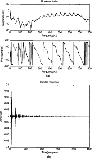
First, we use Roure’s original approach to implement the con-troller by a FIR filter. A sample frequency response of C(ej) in Eq. 共15兲 obtained from experiments is shown in Fig. 5共a兲. To prevent the system from saturation, we multiply the frequency response function by a bandpass filter W(ej) whose pass band is our desired control bandwidth共300⬃600 in our case兲
C⬘共ej兲⫽W共ej兲C共ej兲, (20) where C⬘(ej) represents Roure’s controller filtered by the band-pass filter W(ej). Then the impulse response of Roure’s control-ler, the coefficients of the FIR filter, can be obtained by taking inverse Fourier transform of Eq.共20兲 and then truncating the non-causal part, as shown in Fig. 5共b兲. It is noted that the filter W(z) corrupts the phase of the ideal controller, which could cause per-formance degradation, and even instability. In reality, the effec-tive bandwidth is somewhat less than expected, while instability rarely occurs because the controller gain is considerably attenu-ated outside control bandwidth and sufficient phase margin is preserved.
From the frequency response and the impulse response, the important features of the repetitive controller such as periodic peaks are readily observed. The equivalence of Roure’s controller and Munjal’s ideal controller is evidenced. Because the poles of
the controller are lightly damped, the length of the resulting FIR filter is excessively large. This motivates the use of the following IIR implementation of the Roure’s controller. Similar to the FIR implementation, we filter the frequency response function of Roure’s controller by using a bandpass filter W(ej). Then we apply a frequency domain identification procedure关16兴 to obtain the transfer function Cˆ⬘(z) of the filtered controller which can be implemented by an IIR filter.
As the third approach of implementation, a hybrid structure is proposed in light of the physical structure revealed by the ideal controller. The main idea is to decompose Roure’s controller C(ej) into a FIR part C
FIR(ej) and an IIR part CIIR(ej)
C共ej兲⫽CFIR共ej兲CIIR共ej兲. (21) The IIR part CIIR(ej) should display the pattern of a repetitive
controller: periodic peaks in both frequency domain and time do-main. On the other hand, CFIR(ej) represents transducer
dynam-ics that is generally of low order and can be implemented by a FIR filter.
How can we find the IIR part of Roure’s controller? A straight-forward method is to match the frequency response of the control-ler with the repetitive controlcontrol-ler. However, this proved to be an unsuccessful attempt because of the errors at the resonances. Al-ternatively, we chose to find second order systems, C1(ej) ⬃Cn(ej), to match peaks within the control bandwidth共Fig. 6兲. Then, we cascade these second order systems to get CIIR(ej)
CIIR共ej兲⫽C1共ej兲C2共ej兲¯Cn共e
j兲 (22)
which can be implemented by an IIR filter. Care should be taken to choose the gain level of each stage of second-order system such that no overflow or underflow problem would occur. Hence, the remaining part of Roure’s controller, CFIR(ej), can be expressed
as
CFIR共ej兲⫽ C共e j兲
CIIR共ej兲. (23) Figure 7 shows the frequency response functions of CFIR(ej) and
CIIR(ej). Clearly, we can see that the gain of CFIR(ej) within
control bandwidth is almost a constant, but otherwise is very high. It is then necessary to filter CFIR(ej) with a bandpass filter
W(ej):
CFIR⬘ 共e
j兲⫽W共ej兲CFIR共ej兲. (24)
Inverse Fourier transform of CFIR⬘ (e j
) gives the coefficients of the FIR filter. Finally, we form the controller C⬘(ej) by cascad-ing CFIR⬘ (e
j) and C IIR(ej)
C⬘共ej兲⫽CFIR⬘ 共ej兲CIIR共ej兲. (25) Figure 8 shows the impulse responses of CFIR⬘ (ej), CIIR(ej) and
C⬘(ej). As expected, the length of the impulse response CFIR⬘ (e
j
) is much shorter than the pure FIR implementation of Fig. 5共b兲.
Fig. 5 Roure’s controller„a…frequency response function„b…
impulse response function
Fig. 6 Second order filters of hybrid implementation —: Roure’s controller - -: second order filters
Fig. 7 Frequency response functions of CIIR„j… and
CFIR„j…; - -:CFIR„j…; —:CIIR„j…
Fig. 8 Impulse response functions of hybrid implementation „a…CFIR⬘ „j…, „b…CIIR„j… „c…C⬘„j…
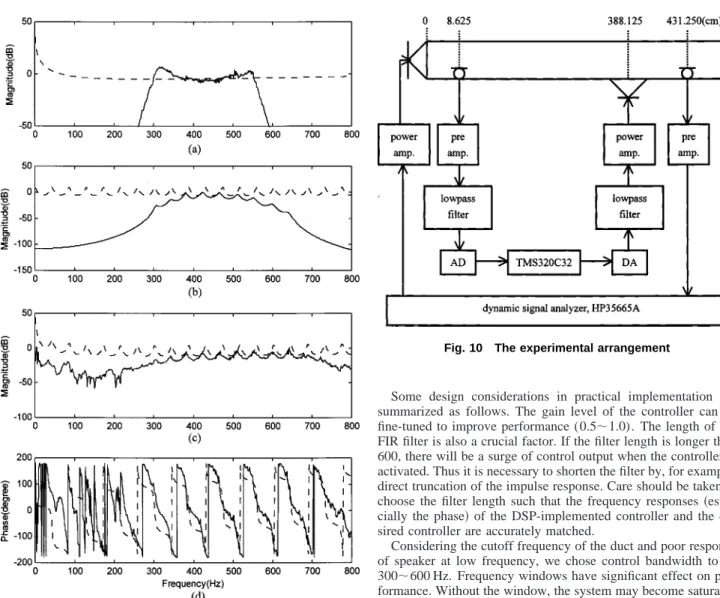
For reference, the frequency response functions between the method of electromechanical constants and the hybrid implemen-tation are as we compared in Fig. 9. The FIR part and the IIR part indeed qualitatively reflect the characteristics of the transducer dynamics and the repetitive controller in the ideal controller. This result manifests the significance of finite source impedance that has been pointed out by Munjal and Eriksson关1兴 but overlooked by many other ANC researchers. Nevertheless, some errors can still be observed in both the magnitude and phase responses, which results in the failure of the method of electromechanical constants.
4 Experimental Verification
The experimental setup is shown in Fig. 10. A duct made of plywood共damping 0.04兲 is used for verifying the proposed ANC controllers. The dimensions of the duct and the locations of trans-ducer are shown in the figure. The length of the duct is 440 cm, and the cross section is 25 cm⫻25 cm. The distance between measurement microphone and control speaker is set to be 379.5 cm such that the causality constraint can be met. The controllers are implemented on a TMS320C32 DSP. The sampling frequency is chosen to be 2k Hz.
Some design considerations in practical implementation are summarized as follows. The gain level of the controller can be fine-tuned to improve performance (0.5⬃1.0). The length of the FIR filter is also a crucial factor. If the filter length is longer than 600, there will be a surge of control output when the controller is activated. Thus it is necessary to shorten the filter by, for example, direct truncation of the impulse response. Care should be taken to choose the filter length such that the frequency responses 共espe-cially the phase兲 of the DSP-implemented controller and the de-sired controller are accurately matched.
Considering the cutoff frequency of the duct and poor response of speaker at low frequency, we chose control bandwidth to be 300⬃600 Hz. Frequency windows have significant effect on per-formance. Without the window, the system may become saturated because of excessive control output. Two types of frequency win-dows are employed in the paper: a bandpass filter (300
⬃600 Hz) and Wiener filter
CFIR⬘ 共e j兲⫽C FIR共e j兲 1 1⫹0.9兩CFIR共ej兲兩2 . (26)
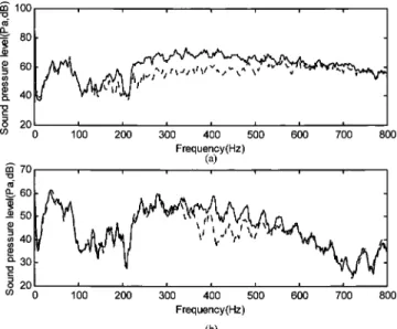
The experimental results obtained from three approaches of filter implementation are summarized in Fig. 11 and Table 1. Total attenuation is the attenuation within the band 300⬃600 Hz. The hybrid implementation shows remarkable performance over the other two approaches: shorter FIR filter than the pure FIR imple-mentation, smaller IIR filter order than the pure IIR implementa-tion and the largest maximum attenuaimplementa-tion 共17.2 dB兲 and total attenuation共4.4 dB兲 among all implementations.
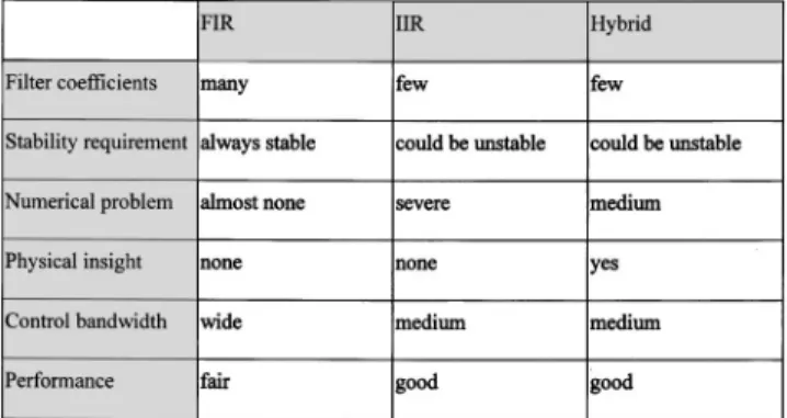
As mentioned previously, the ideal controller is robust in that it is independent of boundary conditions. We shall validate this point by closing the end of the duct by a rigid cap. Figure 12 shows the performance before and after closing the end. The sys-tem remains stable and noise attenuation can still be achieved by using the same controller after closing the end. Note, however, the amount of attenuation is different for two different end conditions. The paper is not intended to overemphasize the superiority of any method over the others. Three approaches of implementing the ideal controller merely have different characteristics, as sum-marized in Table 2. The FIR implementation is straightforward and numerically stable, but often results in excessively long fil-ters. IIR implementation requires only moderate order filter, pro-vided finite word-length effects are properly taken care of. Hybrid implementation bears most physical insight of the ideal controller. Only a low order FIR filter pertaining to the transducer
character-Fig. 9 Frequency response functions of hybrid implementa-tion„a…magnitude of FIR part„b…magnitude of the IIR part„c…
magnitude of the cascaded controller„d… phase of cascaded controller —: hybrid implementation of Roure’s controller; - -: method of electro-mechanical constants of ideal controller
Fig. 10 The experimental arrangement
istics and a low order IIR filter pertaining to the duct characteris-tics are needed in realizing the controller. This feature is particu-larly useful for applications where the system is lightly damped and transducers are omni-directional. It may appear from the com-parison in Table 1 that hybrid implementation outperforms the other methods. As pointed out by the reviewer, the IIR filter should perform better than the hybrid filter if great care was taken to identify the filter coefficients. The experimental results did not
Fig. 11 Experimental results of active attenuation„a…FIR implementation„b…IIR implementation„c…hybrid implementation using bandpass filter„d…hybrid implementation using Wiener filter —: control off, - -: control on
Fig. 12 Experimental results of active attenuation „a… open end„b…closed end —: control off - -: control on
Table 1 Comparison of different implementations of the ideal controller
agree well with the reviewer’s comment which could be due to numerical difficulties in implementing the high order IIR filter
共with 30 lightly damped poles兲. 5 Concluding Remarks
The ideal controller for broadband attenuation of noise in ducts, using spatially feedforward structure, is investigated on the basis of in-depth acoustic analysis and control engineering. The contri-bution of the paper is to unify the acoustic analysis of the ideal controller proposed by Munjal and Eriksson关1兴, and the system theoretic analysis of Hong and Bernstein关7兴 of the zero spillover controller first proposed by Roure关2兴. The ideal controller is ex-tended to a realizable controller in considering the transducer dy-namics and design constraints involved in implementation. The modified controller is then implemented on a DSP platform, using a FIR filter, an IIR filter and a hybrid filter. Three approaches of implementing the ideal controller are verified and compared by experiments. The experimental results showed that the system achieved 17.2 dB maximal attenuation in the frequency band 300–600 Hz.
Along the same line of the preliminary results, future research will be focused on the following aspects. The method of electro-mechanical constants will be revisited such that digital implemen-tation can be further simplified. Actions should be taken to shorten the impulse response of the controller. This can be done by two ways: lining the duct by absorbing materials 共damping increased兲 and using directional transducer arrangement 共acoustic feedback reduced兲. The robustness should be optimally accounted for by using more sophisticated algorithms, e.g., H⬁ instead of direct truncation of filters. For time-varying spatially feedforward
problems, it is well known that the adaptive FIR filter共FXLMS兲 is ineffective and the adaptive IIR filter IIR共FULMS兲 occasionally has convergence problems关4兴. This sheds some light on the hy-brid implementation which requires only a low order FIR filter pertaining to the transducer characteristics and a low order IIR filter pertaining to the duct characteristics. In the future, the sepa-rablility of controller structure could possibly be exploited in adaptive implementation of the duct ANC system.
Acknowledgment
The work was supported by the National Science Council
共NSC兲 in Taiwan, Republic of China, under the project number
NSC 87-2212-E009-022. References
关1兴 Munjal, M. L., and Eriksson, L. J., 1988, ‘‘An Analytical, One-dimensional, Standing-Wave Model of a Linear Active Noise Control System in a Duct,’’ J. Acoust. Soc. Am., 84, pp. 1086–1093.
关2兴 Roure, A., 1985, ‘‘Self-adaptive Broadband Active Sound Control System,’’ J. Sound Vib., 101, pp. 429–441.
关3兴 Elliott, S. J., and Nelson, P. A., 1993, ‘‘Active Noise Control’’ IEEE Signal Process. Mag., 10, No. 4, pp. 12–35.
关4兴 Kuo, S. M., and Morgan, D. R., 1995, Active Noise Control Systems:
Algo-rithms and DSP Implementations, Wiley, New York.
关5兴 Bai, M. R., and Lee, D. J., 1997, ‘‘Implementation of an Active Headset by using the H⬁Robust Control Theory,’’ J. Acoust. Soc. Am., 102, No. 4, pp. 2184–2190.
关6兴 MacMartin, D. G., and Hall, S. R., 1991, ‘‘Structural Control Experiments Using and H⬁Power Flow Approach,’’ J. Sound Vib., 148, No. 2, pp. 223– 241.
关7兴 Hong, J., and Bernstein, D. S., 1998, ‘‘Bode Integral Constraints, Colocation, and Spillover in Active Noise and Vibration Control,’’ IEEE Control Syst. Tech., 6, pp. 111–120.
关8兴 Desoer, C. A., and Kuh, E. S., 1969, Basic Circuit Theory, McGraw-Hill, New York.
关9兴 Clark, R. L., and Bernstein, D. S., 1996, ‘‘Hybrid Control: Separation in De-sign,’’ J. Sound Vib., 214, No. 4, pp. 784–791.
关10兴 Bai, M. R., and Lin, Z., 1998, ‘‘Active Noise Cancellation for a Three-dimensional Enclosure by Using Multiple-Channel Adaptive Control and H⬁ Control,’’ ASME J. Vibr. Acoust., 120, pp. 958–964.
关11兴 Tomizuka, M., Tsao, T. S., and Chew, K. K., 1989, ‘‘Analysis and Synthesis of Discrete-time Repetitive Controllers,’’ ASME J. Dyn. Syst., Meas., Control, 111, pp. 353–358.
关12兴 Swinbanks, M. A., 1973, ‘‘The Active Control of Sound Propagation in Long Ducts,’’ J. Sound Vib., 27, pp. 411–436.
关13兴 La Fontaine, R. F., and Shepherd, I. C., 1983, ‘‘An Experimental Study of a Broadband Active Attenuator for Cancellation of Random Noise in Ducts,’’ J. Sound Vib., 91, No. 3, pp. 351–362.
关14兴 Beranek, L. L., 1996, Acoustics, Acoustical Society of America, Woodbury, NY.
关15兴 Bai, M. R., and Wu, H. P., 1998, ‘‘Robust Control Design of a Sensorless Bass-enhanced Moving-Coil Loudspeaker System,’’ J. Acoust. Soc. Am., 105, pp. 3283–3289.
关16兴 Juang, J. N., 1994, Applied System Identification, Prentice-Hall, Englewood Cliffs, NJ.
Table 2 Summary of implementation methods of the spatially feedforward controller