Rational harmonic mode-locking pulse quality of
the dark-optical-comb injected semiconductor
optical amplifier fiber ring laser
Gong-Ru Lina, Chao-Kuei Leeb, and Jung-Jui Kangb
aGraduate Institute of Photonics and Optoelectronics, and Department of Electrical Engineering,
National Taiwan University
No.1 Roosevelt Rd. Sec. 4, Taipei 10617, Taiwan R. O. C.
bInstitute of Electro-Optical Engineering and Semiconductor Research and Development Center,
National Sun Yat-sen University, 70 Lien-Hai Rd., Kaohsiung 804, Taiwan R. O. C.
Corresponding and Reprint E-mail: [email protected]; [email protected]
Abstract: We study the rational harmonic mode-locking (RHML) order
dependent pulse shortening force and dynamic chirp characteristics of a gain-saturated semiconductor optical amplifier fiber laser (SOAFL) under dark-optical-comb injection, and discuss the competition between mode-locking mechanisms in the SOAFL at high-gain and strong optical injection condition at higher RHML orders. The evolutions of spectra, mode-locking and continuous lasing powers by measuring the ratio of DC/pulse amplitude and the pulse shortening force (Ipulse/Pavg2) are performed to determine the RHML capability of SOAFL. As the rational harmonic order increases up to 20, the spectral linewidth shrinks from 12 to 3 nm, the ratio of DC/pulse amplitude enlarges from 0.025 to 2.4, and the pulse-shortening force reduces from 0.9 to 0.05. At fundamental and highest RHML condition, we characterize the frequency detuning range to realize the mode-locking quality, and measure the dynamic frequency chirp of the RHML-SOAFL to distinguish the linear and nonlinear chirp after dispersion compensation. With increasing RHML order, the pulsewidth is broadened from 4.2 to 26.4 ps with corresponding chirp reducing from 0.7 to 0.2 GHz and linear/nonlinear chirp ratio changes from 4.3 to 1.3, which interprets the high-order chirp becomes dominates at higher RHML orders.
©2008 Optical Society of America
OCIS codes: (060.2310) Fiber optics; (060.4370) Nonlinear optics, fibers; (140.3510) Laser,
fiber; (250.5980) Semiconductor optical amplifiers.
References
1. Z. Li, C. Lou, K. T. Chan, Y. Li, and Y. Gao, “Theoretical and Experimental Study of Pulse-Amplitude-Equalization in a Rational Harmonic Mode-Locked Fiber Ring Laser,” IEEE J. Quantum Electron. 37, 33–37 (2001)
2. H. J. Lee, K. Kim, and H. G. Kim, “Pulse-amplitude equalization of rational harmonic mode-locked fiber laser using a semiconductor optical amplifier loop mirror,” Opt. Commun. 160, 51–56 (1999).
3. Y. J. Kim, C. G. Lee, Y. Y. Chun, and C. -S. Park, “Pulse-amplitude equalization in a rational harmonic mode-locked semiconductor fiber ring laser using a dual-drive Mach-Zehnder modulator,” Opt. Express 12, 907 (2004).
4. C. G. Lee, Y. J. Kim, H. K. Choi, and C. -S. Park, “Pulse-amplitude equalization in a rational harmonic mode-locked semiconductor ring laser using optical feedback,” Opt. Commun. 209, 417–425 (2002). 5. S. Yang, J. Cameron, and X. Bao, “Stabilized Phase-Modulated Rational Harmonic Mode-Locking Soliton
Fiber Laser,” IEEE Photon. Technol. Lett. 19, 393-395 (2007).
6. J. He and K. T. Chan, “All-optical actively modelocked fibre ring laser based on cross-gain modulation in SOA,” Electron. Lett. 38, 1504–1505 (2002).
7. W. Zhang, J. Sun, J. Wang, and L. Liu, “Multiwavelength Mode-Locked Fiber-Ring Laser Based on Reflective Semiconductor Optical Amplifiers,” IEEE Photon. Technol. Lett. 19, 1418-1420 (2007).
8. G.-R. Lin, Y.-S. Liao, and G.-Q Xia, “Dynamics of optical backward-injection-induced gain-depletion modulation and mode locking in semiconductor optical amplifier fiber lasers,” Opt. Express 12, 2017 (2004). 9. G. -R. Lin, I.-H. Chiu, and M.-C. Wu, “1.2-ps mode-locked semiconductor optical amplifier fiber laser
pulses generated by 60-ps backward dark-optical comb injection and soliton compression,” Opt. Express 13, 1008 (2005).
10. G.-R. Lin and I.-H. Chiu, “Femtosecond wavelength tunable semiconductor optical amplifier fiber laser mode-locked by backward dark-optical-comb injection at 10 GHz,” Opt. Express 13, 8772 (2005).
11. W. Rudolph and B. Wilhelmi, Light Pulse Compression (Harwood Academic Publishers, New York), Chap. 3 (1989).
1. Introduction
Rational harmonic mode-locking is one of the promising methods to generate frequency-multiplied optical pulse-train from fiber ring lasers. In general, RHML can be obtained as the modulation frequency of RF synthesizer is detuned to match the condition which satisfies the equation of fm=(n±1/p)fo,where fm, f0, n, p denote the modulation frequency of RF synthesizer, the longitudinal mode spacing in cavity of laser, the HML and RHML orders, respectively. Under RHML operation, the modulation frequency is not equivalent to the cavity round trip frequency fo or its multiples, which is detuned by fo/p (p is an integer number) from the nth harmonic of the RHML regime. In principle, the frequency of RF synthesizer must be detuned very precise to coincide with the RHML frequency of the fiber laser for achieving high-order RHML condition, and the output pulse-train will be repeated at frequency of p*fm. With such an operation, versatile fiber ring laser systems using either the Erbium-doped fiber amplifier (EDFA) or the semiconductor optical amplifier (SOA) as the gain medium were comprehensively investigated. Under high-order RHML operation, the pulse amplitude unequalization and the DC pedestal of pulse becomes significant to degrade the quality of pulses. To overcome these drawbacks, several configurations have been proposed, such as nonlinear polarization rotation (NPR) [1], SOA fiber loop mirror [2], dual-drive Mach-Zehnder modulator [3], and optical feedback [4] based on SOA or EDFA fiber ring laser. For the application of RHML pulse stream, Yang, et al. have shown 10-GHz RHML pulse in a phase-modulated soliton fiber laser and achieved an excellent stabilization performance in a long-term bit-error-rate test [5]. The optical injection induced harmonic mode-locking has emerged as an alternative technique to overcome the traditional limitation on the modulation bandwidth of the SOA contact electrode [6, 7]. Recently, by using a dark-optical-comb as an external injection source, we have also demonstrated the harmonic mode-locked SOAFL with sub-picosecond pulsed output successfully [8-10]. The dark-optical-comb injection is a temporally and spectrally gain-slicing process for reshaping the gain of SOA, such a unique optical cross-gain modulation scheme overcomes the intrinsic drawback of directly modulated SOA, which limits not only the electrical modulation bandwidth but also the modulation waveform. This would greatly facilitate HML or RHML of the SOAFL system as it usually requires unusual modulation waveform to improve the on/off modulation depth and to reshape the gain-window. In this work, we discuss the physical aspects related to the degradation on mode-locked mechanism of the dark-optical-comb injection mode-locked SOAFL at higher RHML orders. At fundamental and high RHML condition, we characterize the frequency detuning range and pulse shortening force to realize the mode-locking quality. The dynamic frequency chirp of the RHML-SOAFL at fundamental and highest RHML order is characterized to distinguish the linear and nonlinear chirp after dispersion compensation. This helps to understand the competition of RHML and continuous wave (CW) lasing of such a SOAFL at high-gain and strong optical injection mode.
2. Experimental setup
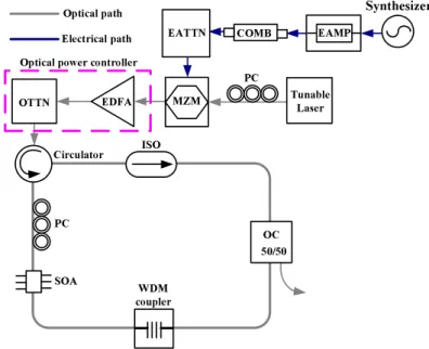
The SOAFL setup shown in Fig. 1 employs the anti-reflection coated SOA (QPhotonics, QSOA-1550) as gain medium, providing a gain spectrum with linewidth of 30-50 nm centered at 1535 nm. The SOA is highly biased at current of 350 mA with its gain strongly modulated by an external dark-optical-comb injection. The dark-optical-comb pulse-train is implemented by nonlinearly driving the external Mach-Zehnder intensity modulator (MZM) with an electrical comb generator at 1GHz. The electrical comb seeded with an 40dB-gain amplified, RF synthesized sinusoidal wave is slightly power-attenuated to match the Vπof 4.5 V found from the transfer function of the MZM, while the MZM and the tunable laser were set at VDC = 1.8 V and 1555.8 nm, respectively. The dark-optical-comb formed and be connected a set of optical intensity controller, consisting of erbium-doped fiber amplifier (EDFA) and optical attenuator (OTTN), and the suitable injection power of dark-optical-comb is 5 dBm. A polarization controller (PC) was required at the input port of SOA to release its polarization dependent gain difference of 3 dB. By detuning the polarization state and the repetition frequency of the dark-optical-comb for optimized gain-modulation depth and mode-locking power, the different RHML condition up to 20th order can be achieved. The Faraday isolator (ISO) is used to ensure the unidirectional propagation and prevent the intra-cavity power dissipation from the injected dark-optical-comb circulated in the SOAFL ring. An output coupler (OC) with power-splitting ratio of 50% is introduced to obtain shortest pulsewidth and pedestal-free RHML pulse-train from SOAFL, and an additional fiber-grating based wavelength-division multiplexing (WDM) filter was used to avoid the regenerative amplification of dark-optical-comb in the SOAFL. The Oscilloscope (Agilent 86100A), dispersion-free auto-correlator (FR-103XL), and optical spectrum analyzer (Advantest Q8384) with resolution bandwidth of 0.01 nm are used to monitor and characterize the mode-locked pulse stream. PC SOA WDM coupler OC 50/50 Synthesizer ISO Circulator EDFA PC MZM COMB EAMP EATTN OTTN Optical path Electrical path Tunable Laser Optical power controller
Fig. 1. Experimental setup. EAMP; electrical power amplifier; COMB: comb generator; EATTN: electrical attenuator; MZM: Mach-Zehnder modulator; EDFA: Erbium-doped fiber amplifier; OC: optical coupler; ISO: optical isolator; WDM: wavelength-division multiplexing; SOA: semiconductor optical amplifier; PC: polarization controller.
3. Results and discussions
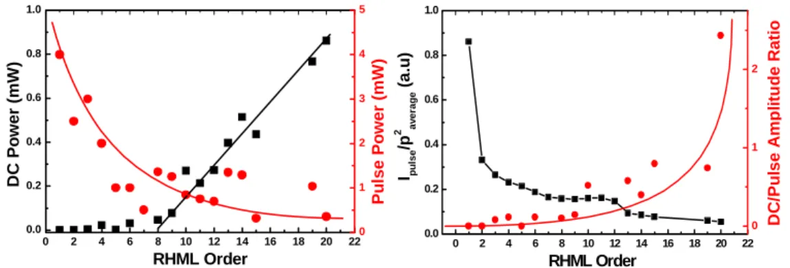
By optoelectronic converting the RHML-SOAFL pulse with an ultrafast photodetector (New Focus 1014 with f3dB= 45 GHz), we observed an increasing tendency of the DC level due to the continuous-wave (CW) lasing added on the RHML-SOAFL pulse-train with increasing RHML orders. It is a direct evidence of the degradation on the RHML mechanism of the SOAFL, which leads us to analyze the power of pulse amplitude and DC level at the difference RHML orders. With these data, we therefore can explain if the higher order RHML really produces bad quality of mode locking associated with an extremely large DC level on the SOAFL pulse-train. As a result, the DC level abruptly enlarges at RHML order large than 7, whereas the pulse amplitude exponentially attenuates with increasing RHML order, as shown in Fig. 2. The SOA gain cannot be completely depleted if the “on” level of the dark-optical-comb injection is insufficiently high, such that the residual gain exists at “off” state of the SOA within one injection modulation period and inevitably leads to continuous-wave lasing of SOAFL with an increasing DC/pulse amplitude ratio. In our case, the best operation relies on increasing the “on” state dark-optical-comb injection power until the SOA gain can be fully depleted, which introduces a largest on/off modulation depth for achieving the best HML. However, the condition is slightly different for the RHML case as the nth RHML pulse can only experiences the SOA gain deviating from its peak value after circulating several round-trips. The RHML pulse-train will inevitably suffer a decreased modulation depth and result in broadened pulsewidth with increasing RHML order. To clarify the evolution of the RHML mechanism in the SOAFL without the effect of detecting bandwidth limit, the contributions of CW lasing and RHML component are further compared by calculating the ratio of CW lasing to mode-locked pulse power from photodetector current, as shown in Fig. 3. It is clearly indicated that the SOAFL gradually transfers from RHML to CW lasing regime with increasing RHML order. The contribution of CW lasing power can remain within 20% at RHML order of less than 12, however, which become greater than 50% as the RHML order goes up to 20. The existence of such a large DC component with the evidence of CW lasing mode obtained from the optical spectrum has elucidated the dominated contribution of CW lading in the SOAFL at RHML order as high as 20.
0 2 4 6 8 10 12 14 16 18 20 22 0.0 0.2 0.4 0.6 0.8 1.0 RHML Order D C Po wer (mW ) 0 1 2 3 4 5 Pu lse Po wer (mW ) 0 2 4 6 8 10 12 14 16 18 20 22 0.0 0.2 0.4 0.6 0.8 1.0 Ipul s e /p 2 av er ag e ( a .u) RHML Order 0 1 2 D C /P u lse A m p li tu d e R a ti o
Fig. 2. The DC and pulse amplitude as a function of RHML order.
Fig. 3. The ratio of DC and pulse amplitude with increasing RHML orders.
Moreover, we have compared the mode-locking strength as a function of RHML order by calculating the pulse shortening force, which is defined as the ratio of peak second-harmonic generation (SHG) signal of autocorrelation trace to the square of fundamental average power (i.e. Ipulse/Pavg2). Such a pulse shortening force is treated as a figure of merit for discriminate the RHML capability of SOAFL, which is a generally used tool to monitor and investigate the build-up dynamics of mode-locking mechanism. For example, the Ipulse/Pavg2 ratio of the SOAFL shown in right part of Fig. 3 is greatly reduces from 0.9 to 0.05 as the rational
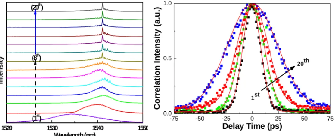
harmonic mode-locking order increases to 20, which interprets that the rational harmonic mode-locking is likely degraded into a small-signal modulation carried on the envelope of a fundamental frequency pulse-strain at the SOAFL output. A higher Ipulse/Pavg2 ratio as well as a more complete mode-locking is thus expectable with a better SHG efficiency, essentially demonstrating competitive nature between RHML and gain switching mechanisms in SOAFL. Furthermore, the phenomenon of a weak gain depletion in the RHML-SOAFL will result in a large residual SOA gain and a high level DC amount at time domain for >7th order RHML conditions, and the 7th order RHML will be the threshold for the transfer of a broadband gain spectra into a narrow CW lasing linewidth. Figure 4 illustrates the RHML-SOAFL spectra corresponding to the harmonic mode locking (HML) and RHML conditions. In comparison, the HML case has a more broadened spectrum with its 3dB linewidth of 12 nm, whereas the spectral linewidth gradually shrinks to 5 nm at 7th RHML order and further decreases to below 3 nm as the RHML order increases up to 20. In the analysis of gain peak at different RHML orders, the gain peak position of RHML-SOAFL is strongly dependent on the amount of the optical feedback in the cavity. Operating the SOAFL at higher RHML orders removes the gain peak and compresses the gain profile of the RHML-SOAFL associated with its wavelength slightly red-shifted to the CW lasing condition. Our experimental observation supports that the ambit of SOAFL red-shifted wavelength from 1535.5 to 1541.5 nm. For these reasons, we conclude and ensure that the RHML mechanism of the SOAFL at high-gain modulation condition will be gradually switched into strong CW lasing and weak mode-locking as the RHML order increases from 7th to 20th order, and the CW lasing mechanism benefits more advantage than RHML mechanism from increasing RHML orders, and the spectra of RHML-SOAFL were fixed at 1541 nm (coincident with that obtained at CW lasing condition). The evolution will reveal the degradation of the mode-locked mechanism at higher RHML orders. 1520 1530 1540 1550 (20th) (8th ) Wavelength (nm) (1st) In te ns it y -75 -50 -25 0 25 50 75 0.0 0.5 1.0 20th C o rr el atio n Inte ns ity (a.u .) Delay Time (ps) 1st
Fig. 4. The development of SOAFL spectra at different RHML order
Fig. 5. The auto-correlation trace of SOAFL at 1st, 5th, 10th, and 20th RHML orders.
To realize the evolution of the pulse waveform with increasing RHML order, the auto-correlation traces of the RHML-SOAFL at different RHML orders are characterized. Figure 5 illustrates that the normalized auto-correlation traces of the SOAFL at 1st, 5th, 10th, and 20th RHML orders gradually changes the pulsewidth from 13.5 to 35 ps after fitting with standard Gaussian profile. In fact, the RHML pulse is still resolvable, however, the peak intensity of the auto-correlation trace is significantly attenuated and its shape is greatly broadened at RHML order of higher than 10. The broadening tendency of the RHML pulsewidth with increasing RHML order correlates well with the behavior of linewidth shrinkage, as shown in Fig. 4. As the RHML order increases beyond 10, the DC/pulse amplitude ratio become
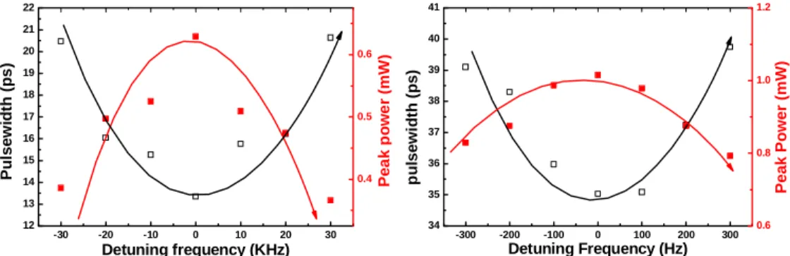
greater than 1 and approach almost 2.4 at 20th RHML order. The detuning ranges of modulating frequency for fundamental HML and 20th-order RHML conditions are shown in Fig. 6 and 7, and it is a useful method to gauge the ability of HML and 20th RHML in the SOAFL. Both of the mode-locked pulsewidth and peak power of the SOAFL at HML and RHML conditions are similar hyperbolic function of detuning frequency. The mode-locking condition with detuning range of ±30 kHz and ±0.3 kHz for the RHML-SOAFL are observed at harmonic and 20th-order RHML, respectively. Apparently, the decreasing detuning capability of 20th-order RHML case exhibits larger collapse than that of fundamental HML case. Nevertheless, the existence of detuning curve has also elucidated that the RHML at higher orders is less contributed to the lasing of SOAFL in comparison with fundamental HML in the SOAFL cavity.
-30 -20 -10 0 10 20 30 12 13 14 15 16 17 18 19 20 21 22 Detuning frequency (KHz) Pu ls e w id th (p s ) 0.4 0.5 0.6 Pe a k p o w e r (m W ) -300 -200 -100 0 100 200 300 34 35 36 37 38 39 40 41 Detuning Frequency (Hz) p u lsewi d th ( p s) 0.6 0.8 1.0 1.2 P eak P o wer ( m W)
Fig. 6. The variation of 1 GHz mode-locked pulse by detuning RF frequency and the detuning range is from -30 kHz to -30 kHz.
Fig. 7. The alterations of 20th order RHML from -300 Hz to 300 Hz.
In particular, a tremendous chirp was raised with the mode-locking of the SOAFL due to the operation of SOA at such high biased condition. Since the extremely high gain of the SOA is depleted by the injected dark-optical comb at a very large duty cycle within one period, only a narrow gain window is left for locking and the frequency chirp of the mode-locked SOAFL pulse becomes extremely large in this condition. Such a chirp cannot be treated as a figure-of-merit for the mode-locking since the mode-locking quality is decided by the phase synchronization among all lasing longitudinal modes in the SOAFL, which can be characterized by the phase noise as well as the timing jitter of the mode-locked SOAFL but not concerned with the dispersion nature (linear and nonlinear dispersion characteristics) of the SOAFL itself. Consequently, the chirp characteristics of the fundamental HML and even the RHML cases in SOAFL were observed and analyzed. First of all, positive chirp for fundamental HML and various order of RHML. For this reason, the dispersion compensation fiber (DCF) is useful for overcoming the linear chirp of SOAFL at HML and RHML cases. Second, we compared the variations on the peak-to-peak frequency chirp value and the pulsewidth at fundamental HML and 20th RHML with difference DCF lengths. In the case of fundamental HML condition, Figure 8 shows the best DCF length is about 65 m and the corresponded pulsewidth is 4.2 ps for the chirp decayed from 3.6 to 0.7 GHz and rising to 1.5 GHz at the variation range of DCF lengths from 10 to 75 m, and it was effectively resisted linear chirp component, and demonstrated 2.8 GHz linear chirp could be compensated at this strong injection and SOA was operated at such high biased condition. Figure 9 emerged 20th RHML order about the evolutions of chirp and pulsewidth at different DCF lengths, the development is more symmetry than harmonic mode locking curves, and the lowest frequency chirp and pulsewidth is 0.2 GHz and 26.4 ps, individually. By analyzing the linear chirp value between the HML and 20th RHML, the efficaciously reduced DCF length from 65 to 10 m is introduced as the RHML increases to 20th order. Such a compensating fiber length reduction
is reasonable and inevitable since the linear chirp effect is greatly attenuated when mode-locking mechanism becomes incomplete due to the decreasing modulation depth at such high RHML orders. Meanwhile, decreasing chirp as increasing order of RHML indicates that the strong gain modulation for SOA within a unit time will form immense chirp value and result in the broader pulsewidth than one with weak gain modulation at higher order RHML. Moreover, the weak gain modulation at higher RHML order operation, the SOA will remain more gain when the RHML order is increasing, while the linear/nonlinear chirp is collapsed and the DC level is concurrently enhanced at time domain.
0 20 40 60 80 4 5 6 7 8 9 10 11 12 13 14 DCF Length (m) P u lsew id th (p s) 0.0 0.5 1.0 1.5 2.0 2.5 3.0 3.5 4.0 Ch ir ppe a k t o pe a k (GHz ) 0 5 10 15 20 25 30 26 28 30 32 34 DCF Length (m) P u ls e w id th ( p s ) 0.0 0.1 0.2 0.3 0.4 0.5 Ch ir ppe a k t o p e a k (G H z )
Fig. 8. The tendencies of pulsewidth and frequency chirp peakto peak in HML.
Fig. 9. The 20th order RHML shows the alterations of pulsewidth and frequency chirp peakto peak.
In principle, the dynamic frequency chirp (Δω=-dφ/dτ) imposed on the output of SOAFL can be derived from the phase modulation, which is proportional to the carrier-induced transient variation on refractive index and gain of the SOA. In our work, the transient gain of the SOA under dark-optical-comb can be described as
2 0 2 0 exp c c g L dg g d τ τ τ τ τ ⎛ ⎞ = ⎜− ⎟− ⎝ ⎠ ,
where g0, L, τc and τ0 denote the gain coefficient, length of SOA, carrier life time, and pulsewith of dark-optical-comb, respectively. In this case, the chirp of the RZ data stream added by the SOA under the backward inverse-optical-comb injection is
e e 2 e e 0 2 0 ( ) 1 = 2 4 4 ( ) ( ) 1 1 exp 4 4 g sp c c c c d dt dP t g R P t dt L dg t L d g L t dt dt α α φ ν ν π π π τ α α π τ π τ τ τ ⎡ ⎤ ⎡ ⎤ Δ = = ⎣Γ − ⎦ ⎢ − ⎥ ⎣ ⎦ ⎧ ⎡ ⎛ ⎞⎤ ⎫ ⎡ ⎤ ⎪ ⎪ = ⎢ − ⎥≅ ⎨ ⎢ ⎜− ⎟⎥− ⎬ ⎢ ⎥ ⎣ ⎦ ⎪⎩ ⎣ ⎝ ⎠⎦ ⎪⎭ ,
where αe, Γ, νg, Rsp and P(t) denote the linewidth enhancement factor, waveguide confinement factor, group velocity, and spontaneous emission rate, respectively. The above function can easily be separated into linear and nonlinear parts by expanding it into a Taylor series with
terms of 0 1 k i i i t ν β =
Δ +
∑
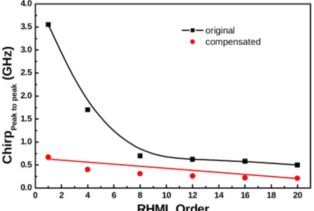
. As a result, the nonlinear chirp will be inevitably occurred in the dark-optical-comb injected SOA since the gain g(t) is a complex profile. Meanwhile, the chirp is a time-derivative Gaussian function under the dark-optical-comb injection. The variation on mode-locking spectral linewidth is also included in the term g0 as described by g0(λ)∝[1+(λ-λ0)2/(Δλg)2], where Δλg is the mode-locking spectral linewidth gradually decreasing with the increasing RHML order due to the incomplete mode-locking procedure athigher RHML orders. In order to demonstrate the relationship of RHML order and frequency chirp, we also analyze the difference between linear and nonlinear chirps of the RHML-SOAFL at original and DCF compensated conditions, as shown in Fig. 10. It is observed that the linear/nonlinear chirp difference for both the original and DCF compensated RHML-SOAFL is rapidly reduced as the RHML increases from 8th to 20th order, such a variation on the decreased ratio of linear and nonlinear chirp is treated as a direct evidence to prove the degradation of intra-cavity gain modulation as well as mode-locking mechanism with increasing RHML order. Only a tiny high-order chirp component is left after DCF based dispersion compensation of the RHML-SOAFL under a weak gain modulation condition at RHML order >8th. For the dark-optical-comb injected SOAFL system operated at either the fundamental HML or the RHML mode, the second-order chirp can be effectively suppressed after linear dispersion compensation with DCF, whereas there is still a part of nonlinear chirp of about 0.3 GHz left in the pulse belonging to the high-order dispersion feature of the SOAFL. The high-order dispersion could be attributing to complex index of refractive change within the gain spectrum of the SOAFL system when driven at high-gain modulation, which cannot be eliminated by simply adding a segment of optical fiber with opposite dispersion nature. A nonlinear dispersion compensation employed by such as soliton compression could thus be mandatory for such a dark-optical-comb injection induced RHML-SOAFL at high-gain condition and high RHML orders.
0 2 4 6 8 10 12 14 16 18 20 0.0 0.5 1.0 1.5 2.0 2.5 3.0 3.5 4.0 Ch ir pP e ak t o p eak (G H z ) RHML Order original compensated
Fig. 10. Variation of the chirp difference as a function of RHML order.
For a mode-locked pulse with a Gaussian profile and a time-bandwidth product (TBP) τ0Δν of 0.44, the relationship between the pulse duration τ with chirp (d2Ψ Ωd 2) and the chirp-free pulse duration τ0 can be expressed as [11]:
2 / 1 2 2 0 2 2 0 1 4ln2 ⎥ ⎥ ⎦ ⎤ ⎢ ⎢ ⎣ ⎡ ⎟⎟ ⎠ ⎞ ⎜⎜ ⎝ ⎛ Ω Ψ + =τ τ τ d d ,
where Ψ and Ω denote as the phase and angular frequency of the RHML SOAFL pulse. For pulses with same spectral bandwidth, a larger chirp indicates broader pulse duration with larger TBP value. The dark-optical-comb injected RHML-SOAFL system with a broader spectral bandwidth will definitely result in larger TBP value rather than a smaller TBP value, unless the dispersion property of the RHML-SOAFL pulse is carefully managed. Therefore, one can estimate the chirp value in unit of fs2 rather than GHz, such that the decreasing chirp with increasing RHML order will be obtained. This also interprets well the reducing chirp behavior of the high-order RHML-SOAFL system shown in Fig. 10. That is, the SOAFL is perfectly mode-locking with a broadband spectrum and largely chirped pulse at fundamental HML condition. However, the evolution on mechanism of such a system from RHML to CW
lasing at higher RHML orders not only shrinks the spectral bandwidth, but also leads to a chirp reduction with increasing RHML order.
5. Conclusion
In summary, the variation on mode-locking parameters such as pulse shortening force, dynamic frequency chirp, and CW to mode-locking power ratio of the SOAFL from fundamental HML to 20th-order RHML conditions by using a dark-optical-comb injection and detuning its repetition frequency are demonstrated. The evolution of the SOAFL from 1st to 20th-order RHML inevitably leads to a continuous-wave lasing, associated with degrading parameters such as reducing spectral linewidth from 12 to 3 nm, increasing DC/pulse amplitude ratio from 0.025 to 2.4, and degraded pulse-shortening-force from 0.9 to 0.05. Furthermore, at fundamental and highest RHML condition, we measure the dynamic frequency chirp of the RHML-SOAFL to distinguish the linear and nonlinear chirp after dispersion compensation. The chirp varies from 3.5 to 0.7 GHz with linear dispersion compensation and the residual chirp of compressed pulses are reduced from 0.7 to 0.2 GHz with corresponding RHML order from 1st to 20th. Meanwhile, the observed pulsewidths are
4.2 and 26.4 ps at harmonic mode locking and 20th RHML orders, respectively. We
discovered there is still a part of nonlinear chirp component which cannot be removed after linear compensation, and the high-order dispersion almost dominates the whole alterations of chirp after RHML order >8th.
Acknowledgments
The authors thank the National Science Council of Republic of China for financially supporting this research under grants NSC 96-2221-E-002-099 and NSC 97-ET-7-002-007-ET.