2130 IEEE TRANSACTIONS ON MAGNETICS, VOL. 43, NO. 6, JUNE 2007
Magnetic Properties of Percolated Perpendicular FePt–MgO Films
An-Cheng Sun
1, Jen-Hwa Hsu
1, P. C. Kuo
2, and H. L. Huang
1Department of Physics and Center for Nanostorage Research, National Taiwan University, Taipei 106, Taiwan Institute of Materials Science and Engineering, National Taiwan University, Taipei 106, Taiwan
Percolated perpendicular FePt–MgO films with a (Fe48Pt52)100 –(MgO) /Pt(001)/Cr(002) structure were prepared by conventional dc magnetron sputtering(x = 0 6 13). Magnetic measurements demonstrate that the coercivity of the magnetic film drastically in-creases from 169 to 285 kA/m as the MgO content is increased from 0 to 0.15 vol.%. However, the grain sizes of the FePt phase do not significantly varying upon doping with MgO. MgO does not appear at the grain boundaries of the FePt phase, but is present as crystalline dots that are uniformly precipitated in the FePt matrix. The MFM images revealed that the domain structure transformed from extending to isolate when the MgO dots precipitated into the FePt grains. Consequently, the MgO dots serve as pinning sites of the domain wall and enhance perpendicular coercivity. Percolated perpendicular magnetic recording is thus regarded as a solution to the problem of thermal instability in ultrasmall grains.
Index Terms—Coercive force, FePt alloy, percolated meida, perpendicular magnetic recording, precipitation.
I. INTRODUCTION
T
HE granular perpendicular medium (GPM) can provide improved recording density with higher thermal stability and better recording resolution [1]–[3]. However, in GPM, the issue of medium noise still critically limits the recording density when the dominant source of medium noise is transition jitter noise [2], [3]. The magnetic grain size must be further scaled down into the nanoscaled range to reduce transition jitter noise while simultaneously maintaining a sufficient medium signal-to-noise ratio (SNR) in an ultra-high density magnetic recording medium [2]–[5]. However, as the magnetic grain size decreases, the thermal magnetic stability is normally degraded. Therefore, the idea of the percolated perpendicular medium (PPM) was recently proposed to solve this issue [6]. The PPM comprises closely packed grains with relatively strong intergranular exchange coupling and well-separated nanometer-sized nonmagnetic columns, or dots, referred to as pinning sites. In this study, perpendicular magnetic FePt media, consisting of well-separated insulating nonmagnetic MgO nanoparticles, were prepared to test this idea. Incorporating MgO nanoparticles into the FePt matrix increases its coercivity. The magnetic hardness mechanism involves switching from domain wall motion in a FePt(001) film to domain wall pinning in percolated FePt–MgO films. Similar investigations have been reported by Suzuki et al. [7], [8]. However, in their study, MgO of 30 vol.% was doped in the FePt phase and the network structure consisting of rectangular MgO and faceted FePt grains was formed. This type of structure is not exactly identical to PPM as proposed previously. Moreover, in our investigation, when a small amount of MgO is incorporated into FePt film, MgO dots behave similar to the nanoinclusions and precipitated in the inner FePt grain. Consequently, the PPM microstructure with randomly distributed nonmagnetic MgO pinning sites inDigital Object Identifier 10.1109/TMAG.2007.892999
Color versions of one or more of the figures in this paper are available online at http://ieeexplore.ieee.org.
our investigation thus effectively enables reduction of transition noise without downgrading the thermal stability.
II. EXPERIMENT
Percolated (Fe Pt ) –(MgO) film (where
vol.%) was deposited on a textured Pt(001)/ Cr(002) bilayer film with 7059 glass substrate in an ultra-high vacuum sputtering chamber. Before the percolated FePt-MgO films were deposited, the substrate was heated to C to prepare the Cr(002) underlayer and the Pt(001) buffer layer, and then to C to deposit FePt–MgO films. The thicknesses of the FePt–MgO film, the Pt buffer layer, and the Cr underlayer were set to 20, 3, and 70 nm, respectively. Various rf sputtering powers of MgO were used to vary the MgO content. The crystalline phases and microstructures of the films were iden-tified by X-ray diffraction (XRD) using Cu–K radiation and high-resolution transmission electron microscopy (HRTEM), respectively. The chemical composition of the magnetic FePt layer was determined by energy dispersive spectroscopy (EDS), and the composition of the FePt was Fe Pt . Since MgO does not alloy with the magnetic FePt phase, the MgO content of the magnetic FePt matrix was determined by calculating vol.%, where denotes the sputtering rate. The thicknesses of the film were measured by atomic force microscopy (AFM). Magnetic properties were measured using a vibrating sample magnetometer (VSM) at room temperature with a maximum applied field of kA/m. Domain structures were observed using a magnetic force microscopy (MFM) in an ac-demagnetized state.
III. RESULTS ANDDISCUSSION
Fig. 1(a) displays the X-ray diffraction patterns of (Fe Pt ) -(MgO) /Pt/Cr trilayer films with various MgO con-tents. Except for the peak of the Cr(002) underlayer, all visible peaks are attributed to the fcc or the FePt phase, indicating that no new phase was formed. Since the MgO content is low, the peaks that correspond to MgO were not observed. Addition-ally, an excellent ordered FePt(001) texture without FePt(111) and (200) peaks is present when MgO is absent, revealing that a pure FePt(001) film with good perpendicular magnetic anisotropy property was obtained [9]. In Fig. 1(a), the intensity 0018-9464/$25.00 © 2007 IEEE
SUN et al.: MAGNETIC PROPERTIES OF PERCOLATED PERPENDICULAR FePt–MgO FILMS 2131
Fig. 1. (a) X-ray diffraction patterns and (b) out-of-plane coercivity(H ?) and long-range ordering parameter(S) of (Fe Pt ) –(MgO) /Pt/Cr tri-layer films with various amounts of MgO contents.
of the FePt-ordered peaks was predominant, and then fell as the MgO content increased. The ordered FePt(002) peak transformed into the disordered fcc FePt(200) peak and the ordered FePt(001) peak disappeared when MgO reached 6.13 vol.%. The appearance of the disordered FePt(200) peak sug-gests a degraded (001) texture of the FePt phase. Fig. 1(b) plots the out-of-plane coercivity and long-range ordering pa-rameter versus MgO content. first increased markedly as the MgO content increased from 0 to 0.15 vol.%, and then declined significantly as the amount of MgO increased. A peak
value of 285 kA/m was found at MgO vol.%.
However, remained the same, at approximately 0.74, at a MgO content of between 0 and 0.15 vol.%; it then decreases rapidly as the MgO content increases. Therefore, the drop in when MgO vol.% is primarily associated with the decline in the ordering parameter . However, the dependences of and on MgO content between 0 and 0.15 vol.% are not similar. This finding is rather unexpected. The enhancement in hysteresis coercivity is typically caused by an improvement in ordering [10], [11]. Thus, the large increase of with the incorporation of a small amount of MgO should have another origin, which will be discussed later.
Comparing the integrated intensities and positions of FePt(001) and (002) peaks from FePt film with those from the composite (FePt) –(MgO) film, as displayed in Fig. 1(a), reveals no detectable difference between the film structures, suggesting that both had similar alignments. How-ever, a large difference between values was discovered, implying that the microstructure and magnetization behavior of both films may differ [12]. The microstructure of the com-posite (FePt) –(MgO) film was examined to elucidate the role of MgO in the FePt matrix. For comparison, the microstructure of FePt film was also studied. Fig. 2(a) and (b) presents plane-view TEM bright field images. The images revealed that doping with MgO does not significantly change the grain sizes of the FePt phase. The plane-view TEM bright field images reveal that many white MgO dots (identified with TEM-EDS) were well separated throughout the FePt matrix in (FePt) –(MgO) /Pt/Cr trilayer films. The inset in Fig. 2(a) presents the lattice structure of MgO dots of the dotted circle in Fig. 2(a). Undoubtedly, the MgO dots are crystalline with a diameter of about 3 nm. A better lattice matching at the FePt/MgO interface was also observed; MgO may be precipitated inside the FePt grains, unlike in GPM films, in
Fig. 2. Plane view TEM images of (a) (FePt) –(MgO) /Pt/Cr and (b) FePt/Pt/Cr trilayer films, respectively. The inset in Fig. 3(a) is the lattice struc-ture of the MgO dot located within the dotted circle of Fig. 3(a).
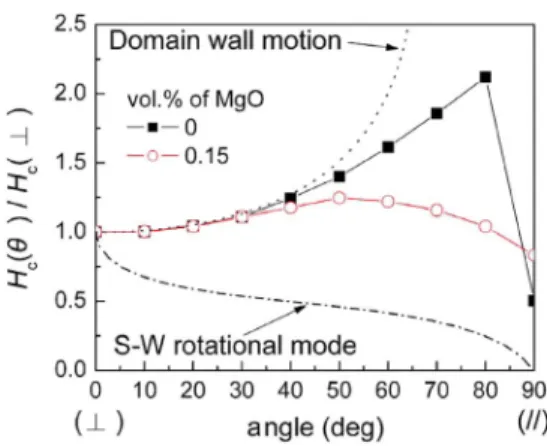
Fig. 3. Angular variation of the coercivity of FePt/Pt/Cr and (FePt) –MgO /Pt/Cr trilayer films.
which nonmagnetic insulator material, such as Al O [13] or SiO [14], [15], is preferred to segregate at magnetic grain boundaries. However, in the case of the FePt–MgO film, MgO dots were surrounded by the FePt phase, as in the percolated film. As shown in Fig. 2(b), white dots were absent from the image of the FePt/Pt/Cr trilayer film.
The angular variation of the coercivity was determined to understand the magnetization reversal process. The results are plotted in Fig. 3. The coercivities at and are related to applied field normal and parallel to the film plane, respec-tively. Generally, for domain wall motion mechanism, the coer-civity at should be proportional to /cos , where is the angle between the applied field and the easy axis of the uni-axial anisotropy and is the coercivity when the applied field is in the direction of the easy axis. For comparison, the varia-tion of coercivity with the angle for the rotation mechanism derived from the Stoner–Wohlfarth model was also illustrated in Fig. 3. As shown in Fig. 3, the magnetization reversal behavior of the FePt/Pt/Cr trilayer film is close to the domain wall motion over a wide-angle region, suggesting a strong coupling between magnetic domains [16]. The domain wall moves progressively through the magnetic grains. However, when the MgO dots were segregated into inner FePt grains, the domain wall motion was impeded by MgO dots and became discontinuously propagated. The MgO dots play a role of pinning sites to retard the domain wall motion. As a result, the magnetization reversal tends to be closer to the rotation mode as indicated in Fig. 3.
2132 IEEE TRANSACTIONS ON MAGNETICS, VOL. 43, NO. 6, JUNE 2007
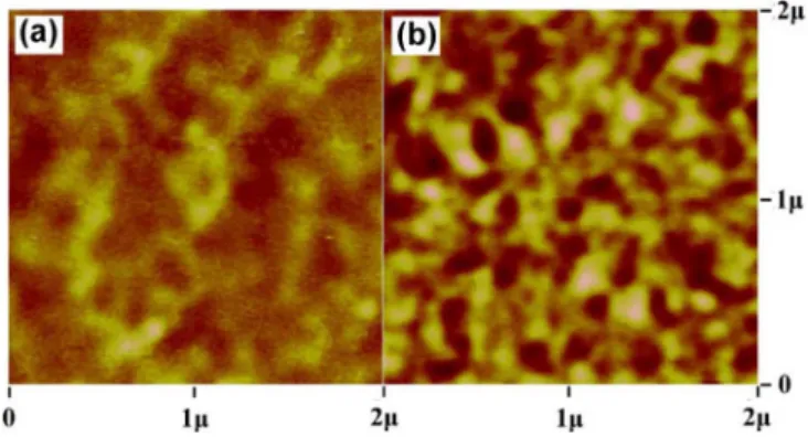
Fig. 4. Domain structures of (a) FePt/Pt/Cr and (b) (FePt) –(MgO) /Pt/Cr trilayer films.
Fig. 4(a) and (b) illustrated the magnetic domain structures of FePt and (FePt) -(MgO) films in an ac-demagnetized state, respectively. In Fig. 4(a), the extending domains were found. The average domain size was 250–300 nm, and the boundaries were blurred. However, when MgO precipitated in the FePt grains, the domain size was reduced to 150–200 nm as shown in Fig. 4(b) and the boundaries were easily observable, revealing the existence of pinning sites introduced by MgO dots because the domain walls are located at the energy barrier (MgO dots herein) during demagnetization [17]. The situation is the opposite of that in FePt film, in which the domain wall moves a long distance with few hindrances during the demag-netization process. Consequently, the extending domain was formed with a blurred boundary. This fact strongly indicates that the domain wall pinning effect occurs in MgO-doped FePt thin film.
Since MgO dots are embedded in FePt matrix, these nano-size inclusions will act as major hindering sites to the domain wall motion and, consequently, enhances the coercivity . On the other hand, microstress caused by the lattice mismatch be-tween FePt(001) and MgO(002), which is roughly around 9.0 % [7], also existing around MgO dots, may cause an additional hindrance and further increase coercivity. However, further in-creasing the MgO content to more than 0.31 vol.% converts PPM into GPM, since the excess MgO is segregated at FePt grain boundaries. Furthermore, increasing the MgO content will raise the ordering temperature, inhibiting the formation of or-dered FePt(001) phase [18], as shown in Fig. 1.
IV. CONCLUSION
Percolated FePt–MgO films were prepared on a textured Pt(001)/Cr(002) bilayer film using the 7059 glass substrate. MgO dots were uniformly precipitated in the FePt matrix and acted as pinning sites to the domain wall motion, causing an enhancement of when a small amount of MgO was doped into FePt grains. This fact demonstrates the benefits of using the percolated perpendicular medium to further increase the storage density of magnetic recording.
ACKNOWLEDGMENT
This work was supported by the Ministry of Economic Affairs of Taiwan under Contract 95-EC-17-A-08-S1-0006.
REFERENCES
[1] W. H. Jiang, H. Muraoka, Y. Sugita, and Y. Nakamura, “Thermal re-laxation in perpendicular double-layered media,” IEEE Trans. Magn., vol. 34, no. 4, pp. 1645–1647, Jul. 1998.
[2] A. Takeo, Y. Takahashi, Y. Tanaka, K. Miura, H. Muraoka, and Y. Nakamura, “Precise noise characterization of perpendicular recording media,” J. Appl. Phys., vol. 87, pp. 4987–4989, May 2000.
[3] M. Hashimoto, K. Miura, H. Muraoka, H. Aoi, and Y. Nakamura, “In-fluence of magnetic cluster size distribution on SNR and bit error rate in perpendicular magnetic recording,” J. Magn. Magn. Mater, vol. 287, pp. 123–127, Feb. 2005.
[4] S. Ishio, T. Wasiya, H. Saito, J. Bai, and W. Pei, “Magnetic reversal field map combined with medium noise analysis in CoCrPt-SiO granular perpendicular recording medium,” J. Appl. Phys., vol. 99, p. 093907, May 2006.
[5] S. J. Greaves, H. Muraoka, and Y. Kanai, “Discrete track media for 600 Gbits/in recording,” J. Appl. Phys., vol. 99, p. 08F903, Apr. 2006. [6] J.-G. Zhu and Y. Tang, “A medium microstructure for high area density
perpendicular recording,” J. Appl. Phys., vol. 99, p. 08Q903, Apr. 2006. [7] T. Suzuki and K. Ouchi, “Sputter-deposited (Fe—Pt)—MgO com-posite films for perpendicular recording media,” IEEE Trans. Magn., vol. 37, no. 4, pp. 1283–1285, Jul. 2001.
[8] T. Suzuki, H. Muraoka, Y. Nakamura, and K. Ouchi, “Design and recording properties of Fe—Pt perpendicular media,” IEEE Trans. Magn., vol. 39, no. 2, pp. 691–696, Mar. 2003.
[9] A.-C. Sun, P. C. Kuo, J.-H. Hsu, H. L. Huang, and J.-M. Sun, “Epitaxial growth mechanism ofL1 FePt thin films on Pt/Cr bilayer with amor-phous glass substrate,” J. Appl. Phys., vol. 98, p. 076109, Oct. 2005. [10] J. Wan, Y. Huang, Y. Zhang, M. J. Bonder, and G. C. Hadjipanayis,
“Particulate FePt/Ag(C) films with strong perpendicular anisotropy,” J. Appl. Phys., vol. 97, p. 10J121, May 2005.
[11] Y. F. Ding, J. S. Chen, E. Liu, and J. P. Wang, “Dependence of mi-crostructure and magnetic properties of FePt films on Cr Ru un-derlayers,” J. Magn. Magn. Mater., vol. 285, pp. 443–449, Sep. 2005. [12] J. D. Livingston, “A review of coercivity mechanisms,” J. Appl. Phys.,
vol. 52, pp. 2544–2548, Mar. 1981.
[13] Y. K. Tahahashi and K. Hono, “Interfacial disorder in theL1 FePt particles capped with amorphous Al O ,” Appl. Phys. Lett., vol. 84, pp. 383–385, Jan. 2004.
[14] J. Z. Shi, S. N. Piramanayagam, C. S. Mah, H. B. Zhao, J. M. Zhao, Y. S. Kay, and C. K. Pock, “Influence of dual-Ru intermediate layers on magnetic properties and recording performance of CoCrPt-SiO per-pendicular recording media,” Appl. Phys. Lett., vol. 87, p. 222503, Nov. 2005.
[15] G. Sáfrán, T. Suzuki, K. Ouchi, P. B. Barna, and G. Randnóczi, “Nano-structure formation of Fe-Pt perpendicular magnetic recording media co-deposited with MgO, Al O , and SiO additives,” Thin Solid Films, vol. 496, pp. 580–584, Oct. 2006.
[16] T. Suzuki, N. Honda, and K. Ouchi, “Magnetization reversal process in polycrystalline ordered Fe-Pt(001) thin films,” J. Appl. Phys., vol. 85, pp. 4301–4303, Apr. 1999.
[17] R. D. McMichael, F. Vajda, and E. Della-Torre, “Demagnetized-state dependence of henkel plots. II. Domain wall motion,” J. Appl. Phys., vol. 75, pp. 5692–5694, May 1994.
[18] C. P. Luo and D. J. Sellmyer, “Structural and magnetic properties of FePt:SiO granular thin films,” Appl. Phys. Lett., vol. 75, pp. 3162–3164, Nov. 1999.
Manuscript received October 31, 2006; revised February 8, 2007 (e-mail: [email protected]).