A Low-Error
and
Area-Time
Efficient Fixed-Width Booth Multiplier
Min-An Song, Lan-Da Van*, Ting-Chun Huang,
and
Sy-Yen
Kuo
Department of Electrical Engineering,
National TaiwanUniversity, Taipei, Taiwan,
R.O.C*Chip
Implementation
Center(CIC),
NationalApplied
ResearchLaboratories,
Taiwan,
R.O.C.E-mail: sykuo(&cc.ee.ntu.edu.tw
and ldvanicic.org.tw
Abstract
Inthispaper,wedevelop a new methodology for designing a lower-errorand area-time efficient 2 s-complement fixed-width Booth multiplier that receives two n-bit numbers and produces
ann-bit product. By properly choosing the generalized index and binary thresholding, wederive abettererror-cojmpensation bias
to reduce the truncation error. Since the proposed error-compensation bias is realizable, the constructing low-error fixed-width Booth multiplier is area-time efficient for VLSI implementation. Finally, we successfully apply the proposed fixed-width Booth multiplier to speech signal processing. The simulation results show that the perfoirnanceisistiperior tothat using the direct-truncation fixed-width Booth multiplier.
1. Introduction
In many digital signal processing (DSP) applications such as digital filters [6, 7] and wavelet transform, it is desirable to maintain fixed-width output word through tihe arithmetic operations. So, a low-error fixed-width multiplier [5-8] that receives ann-bitmultiplieras well as an n-bit
multiplicand
and producesann-bit
outputprodtictisthemostimportant processing
element
fordigital
computing engine. In view ofthe
algorithm
level,mostfixed-width
multipliers
areb-ased
oneither the Baugh-Wooleyalgorithm[I1
orthe Booth algoirithm [2, 31.
The Baugh-Wooley based fixed-width multipliers[5-7]
have been widely studied. Kingand Swartzlander [5] analyzed an adaptive error-compensationbias and proposedanri-bitfixed-width multiplier. In[6, 7],wegeneralized thiskind of Baugh-Wooley based fixed-width multipliers by properly choosi.ng the generalized index and binary thresholding. Thus, several 'lower-error and area-efficient fixed-width multipliers canbe obtained. However, thearea-timeefficient fixed-width multiplier cfannot be filly achieved by the Blauth-Woolcy based fixcd-widtl
nmltiplicrs. TIhercbore,
thc fixed-width Bootilalgoritlihi
iF,currcntly
onie
of thercscarclh
topics.The Boothalgorithm iswidelyused in theimplementation of ASIC-oriented products
because
a highler-speed and smaller multiplier can be obtained. The modified Booth algorithm was proposed by the MacSorley [3] in which a triplet of bits is scannedat atime. It is known that the recodingtechniqueofthe modified Booth algorithm has two mainadivantages.
One is that almosthalf the partial productszompared
totheBaugh-Wooley multiplier can be saved. Hence, the number of rows of the subproductarraycanbereducedby 2.Theofther
isthat,basedonthe firstadvantage, thecriticaldelay titne can,beshorterthanthat of the Baugh-Wooley multiplier. Area
savinig
of a fixed-width Booth multiplier can be achieved by directly truncating n least significantproduct bits and ,reserving nmostsignificant product bits. With this method,sig,nificant
truncation errors would be introduced since no error c,ompensation is considered.Thus,
the Booth-based scheme in [8] has been proposed to reduce thetruncation error;however, the proposed scheme
[8]
that lacksfor systematic analysis and derivation does not be a systematic methodology. In this paper, we are motivated to propose asystematic design methodology for low-error area-time efficient Booth multipliers. Themethodology includes the following steps in order: I) Propose an error-compensation bias with a new
binary thresholding; 2) simulate the value of K and error performance of the proposed error-compensation bias usingour
generalized index, and then select the best index having lower error and
satisfying
thesamevalue of K for small width n;and 3) construct a low-error Booth multiplier structure. Based on our methodology, the resulting error compensation circuit can be easily realized without any area overhead under the limited truncationerror.Theorganization of this paper isasfollows. The modified Boothalgorithm isconciselyreviewed in Section 2. In Section 3, we propose a better error-compensation bias and presentthe simulation results for small width n. Theimproved error-compensation biascan bemappedto a new structure. The performance of the proposed fixed-width Booth multiplier are described in Section 4. Finally, brief statements in section 5 concludethepresentation.2.
Modified
Bootht
Mtiltiplier
Considering the multiplication of two 2 s-complemilent integers withn-bit multiplicand A and n-bitmultiplier B as
2n-I
P=AB=
Z,P,2i
i=O
(1)
n-2 n-2
where A= -a
2n-1
+Eai2'
, B=-bn12
+Ebj2
j,
and1=O j=0
P1 denotes the 1-th output product bit. Note that a, and
b,
ind(licate
dlata bits of multiplicandand(i
miul(iplier,
respectively. Assumne n is eveCI and theu-bitimultiplier Ii canberewritten(n-2)/2
B=
(b2i
l+b2i-2b2i+1)2
,i=O
(2) where
b-1
=0.Note that thetermsinthe bracket inEq (2)have values of{-2,-1, 0, 1,2).
Eachrecodedvalueperformsacertain operationonthemultiplicandA, and thenthe multipleadditionsateach stagewould berequired inordertogeneratethecorrect
partialproduct. Itisworthmentioningthat theoperationof-A
canberealizedby the inversion ofthe
multiplicand
and addition of 'I at the least significant bit as illustrated in Table I.Substituting Eq. (2) into Eq. (1),wecanobtainEq.(3)as
(n-2)/2 (n-2)/2
P=AB=
E(b2i_
±+b2i-2b2+1,)A22i
=Si,
i=O i=O
(3)
where
Si
=(b2,i
1+b2i
-2b2+
I)A22i
, and it is known thatthe scanning oftriplets begins fromb-I
to the MSB with one-bit overlapping.Thus,only the number ofn/2 partial-productrowsneeds to be computed.
Table 1:Modified BoothEncodingTable
b21+,
b2i
b2i-I
Operationon ADD to LSB A o 0 0 0 0 0 0 1 -A 0 0 1 0 +A 0 0 1 1 +2A 0 1 0 0 -2A 1 0 1 -A I 1 0 -A I 1 1 0 0_O
I X,7 k7,@ 51,6I
3~
©D
S.
S,,
s,"
I IX & I4 II
I
I
I
l l
ll
--.Tncated
pt I ,r -- -- -___________ - -'% 1-.6XSo.,
4S%.
3 2 S .,S. I SuI::4SA3 S,2 SM S,-I,IIQ,12],o
IS,S;,
S2t --IIl>13121Cr' ) tt
VVV 1
t
-t
t
P15P14 P13
P12PllPIO
P9P8
's"Fig. 1. Modified Booth
partial-product diagram
withsign-generatesignextensionscheme foran8x8
multiplier.
Soas tosimplify the representation ofthe bit-productofeach rowforthe Boothalgorithm,wedefinethe
following
notationS
,n22i+n-lI
2i+n-2 S 2i2S1 "
i,n-l~
+Si,n-22
+..+
S1,0
(4)where
S,jj
represents thebitproductof the i-throw. Basedonthe conventional Booth arithmetic operations,sign extension of the partial products are required for each stage. However, the extended
sign
bits resultinalargerpowerandarea.Accordingto thesign-generate
sign
extension scheme[4],
for an 8by
8multiplier, the
sign
of thefinal resultcanbeexpressed
as1J
23
2iJ
9s-(So,72)2+(SI7Z2')
2(S2,7Z2')24
+(S3,7Z2J)26
j=8 j=8 j=8 j=8 9 8 - 1 13 12 =(2+S0,72
)+(2"+S 2721 )+(2 +S272 )+(2"
+S324)+2
2(5)
where S is the final result sign. From Eq. (5), the partial products ofthe Boothalgorithm only needtoadd two elements (1,
Si7
) for each row and add an extra 'I in the28
-weight position as shown in Fig.1, where main and remain represent main part and remain part of the least significant bit (LSB), respectively. Thus, thesign-generate sign extension scheme can reduce a lot of redundant full adders compared to the conventional sign extension method. The architecture of the Booth Multiplieras shown inFig.2 consists of Booth encoders, selectors (sel),full adders(FA)andhalf adders(HA).TheBooth encoder generates Ctrli [O:2] signals to control the selector tochoose -2A, -A, 0, IAor2A.
3.
Design
of Fixed-Width
Booth
Multiplier
The 2n product fornbyn 2 s-complement multiplicationcanbedivided intotwosectionsas
P=AB=MP + LP. (6)
Fig. 2. An8X 8 modified Booth
multiplier using sign-generate
sign extension
scheme.The
most
accuratetrunication1
prodLlct
isgiveni
by
P_MP++
aTempx2n,
UTemp
=ILPI
r-(7)
(8)
Without loss ofgenerality,forn=8,Eq.(8)canbe denotedasI
(S3,1
+S2.3
+S '0,7)-+22(S3,0
+ -+SO,6
L2
22
Cr7eml9) 1
+
CfrI3[2D
+ ...+ ISo,
I +I!
(SO,O
+Ctrlo[2
1)
r(9)
Thenwedefine the
following
termsEmain =
S3,1
+S2,3+SI,s
+SO,7,
Eremain
= I(S3o0
+S2,2
+Sj,4
+SO,6
+Ctrl3(21)
2'
+... + 7
(So,o
+Ctrlo[2])
27
Thus;,
we canrewriteEq.(9)ascr
Temp
=[I(Emain
+Eremain
)]-(10)
(I
1)
(12)
591
-Itis convenienttoperform exhaustive simulation ifwedefine the generalized index. Here the generalized index for 8 by 8 multipliersis definedas
i9M&x(q32q22q71qO)
=<S3,1
>q3+<S2,3
>q2+ <S1,s
>q +<So,7
>q (13)where the binary parameters q3,
q2,q1
andqo
E(0,1),
and the operator< TT
,if
q,=0(T, ,if q =I
(14)
in which T is the complement of
binary
T . Furthermore,0indeX(q3,q2,ql,qO)
is
referred
toas as0Q,
where
Q=q
3x23
+q2
x22
+q1
X21
+qo
x20.
(15)
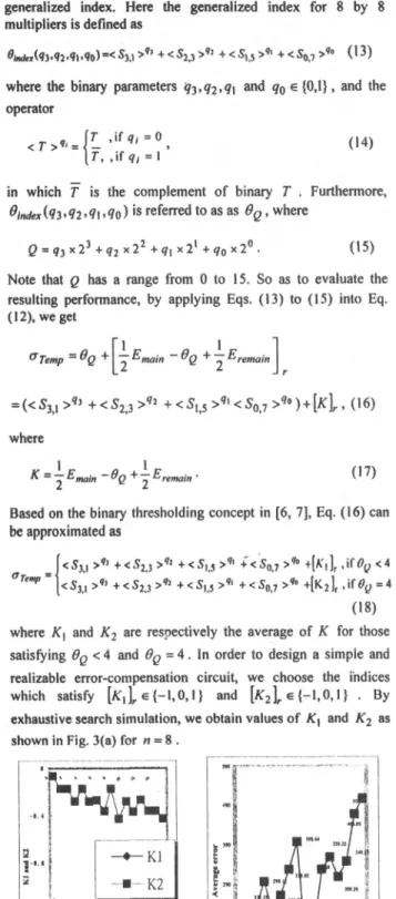
In accordance with the rounding values of K1 and K2, we simulate average error as shown in Fig. 3(b). Considering the
goal
oflower error and the restriction ofK, we can find thatOQ=O
index has betterperformance
as shown inFig.
3(b)
with[KI
Jr
=-I and [K2Jr
=0 for n = 8 . Thus, the simple error-compensationcircuitcanbedescribedasS3,1
+S2,3
+S,,5
+S0,7
-1 ,ifOQ=o
<4aQ=o
=S3,1
+
S2,3
+
S+,s
+
S0.7
+
°,
if
OQ=0
=4
(19) where Q=O=S31
+S23+S5
+So,7
* Eq. (19) has beencompletely
simulated for n.16 and can be mapped to a newstructure as shown in
Fig.
4. Note that the error-compensation circuitonly
needsthree ANDgates.Note that Q has arange from 0 to 15. So as to evaluate the resulting performance, by applying
Eqs.
(13) to (15) into Eq.(12),
weget
6Temp
=OQ
+[
Emain
0Q
+
IEremain]
=w(<e3r
q3
+<S23
>92
+
<eS15
>q,
<SO7
qo
)+[K]r
9(16)
where
K=2Emain-fQ
+I
Eremain° (17)Based
onthebinary
thresholding
concept
in[6,
7], Eq.
(16)
can beapproximatedas[<S3.1
>9)
+
<S2.3
>9'
+<
SO
>q'
+<SOJ7 >q°
44K,
1r
if
Oy
<
4
emp
{<S3,1
>71
+<S2,3
>92
+<S1,,
>9
+<s0,7
>q
+[K2]
,
if =4
(18)
where K1 and K2 are
respectively
theaverage ofK forthose satisfyingOQ
<4 and=Q
4. In order todesign
asimple
and realizableerror-compensation
circuit,
we choose the indices whichsatisfy
[KuIr,e
(l,0,l)
and[K2J]rE{-1,0,1)
.By
exhaustive search
simulation,
weobtain values ofK1 andK2
asshown inFig.3(a)for n=8.
-EK2
20
m
Q 20
Fig. 3.(a) Values ofKI and K2 versusdifferentQofthe
binary
thresholding. (b)
Averageerrorsby
exhaustive searchsimulation versusdifferentQofthebinary
threshoding
for n=8.B[:3:1 | Booth |Ctrli(2:01
,4
P P 12 Pa11 P 0 P9 PS
Fig. 4. Proposed low-error fixed-width 8 x 8 Booth multiplier with
4.
Performance-and
Application
Discussion
In this section, we first simulate errorperformance in terms of maximum error, average error, and variance of error as listed in Trable 2 between the direct-truncation multiplier and the proposedfixed-width Booth multiplier. It is clearly seen that the new structure can achieve better error performance than the direct-truncation Booth multiplier. Regarding the number of gates and the critical pathdelay timeissuesaslisted in Table 3, comparison results show that the new Booth multiplier saves much areacost with respect to thefull-precision Booth multiplier based on the sign-generate sign extension scheme. Most importantly, the gate count and critical delay time of the proposed structure are close to those of the direct truncation multiplier, respectively. Thus, the proposed fixed-width Booth multiplier has the area-time efficient feature with better error performance. On the other hand, we apply the proposedfixed-width multiplier to the 35-tap FIR filter for speech processing
(9].
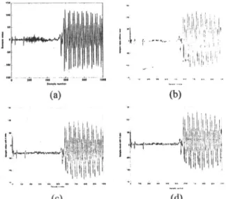
For convenience of comparison of various fixed-width multipliers, we take 1000 samples for the consonant part and vowel part of"Chicken"asshown inFig. 5(a). Weareconcerned with whether thefiltered waveform isaccuratevia ourproposedfixed-width multiplier,sothecorrect standardoutputis required. We useerror-free output as a standard, which is used to compare theaccuracy performances of fixed-width multipliers. Fig. 5(b) shows the standard filtering outputsignals andFigs. 5(c) shows thefiltering output signals processed by the 35-tap low-pass FIR filterapplying a directtruncation fixed-width multiplier. Using direct truncationmultiplier, it isseenfromFig. 5(c) that there are large averageerrorand variance of errorsin the consonant part. The smaller average error and variance of the errors especially for consonant part isobtained by usingourproposed fixed-width Boothmultiplierasshownin Fig.5(d).
5.
Conclusions
Thispaperdevelopsa newmethodology fordesigning a low-error and area-time efficient fixed-width Booth multiplier. By properlychoosingbinary thresholding andthegeneralized index, we can derive a better error-compensation bias to improve the truncation error. Furthermore, this error-compensation bias can be easily constructed as a lower-error fixed-width Booth multiplier. Itis very suitable for VLSI digital signal processing applications where the accuracy, area, and speed issues are crucial.Finally, we successfully apply the proposed fixed-width multiplier to a digital FIR filter for speech processing application.
(a)
11'..Ig;, tt, s.. 18 tw s .,. j,, ,g, 11l;1n'1','' .* .... ., ,* .w .... .0 (b)(c)
(d)Fig. 5. (a) Original inputvoice signal, (b) standard output voice signal, (c)outputsignals usingthe directtruncationstructureand (d) outputsignals usingtheproposedBoothmultiplierstructure.
6.
References
[I] C. R. Baugh and B. A. Wooley, "A two's complement parallel array
multiplication
algorithms", IEEE Trans. Comput.,vol.C-22, pp. 1045-1047,Dec. 1973.(2]
A. D. Booth, "A signed binary multiplication technique," Quarterly Journal of Mechanics andApplied Mathematics, vol.4,part5, pp.236-240, 1951.[3] 0. L. MacSorley, "High-speed arithmetic in binary computer",Proc.IRE,vol.49, pp.67-91, 1961.
[4] E. de Angel and E. E. Swartzlander, Jr., "Low power parallelmultipliers,"IEEE VLSISignalProcessing IX, 1996, pp. 199-208.
(5]
E. E. Swartzlander, Jr., "Truncated multiplication with approximaterounding," inProc. 33rdAsilomarConferenceonSignals, Systems, and Computers, 1999,vol. 2,pp. 1480-1483.
[6]
L. D. Van, S. S. Wang, and W. S. Feng, "Design of the lower-error fixed-width multiplier and its application", IEEE Trans. Circuits Syst. 11, vol. 47, pp. 11 12-1118, Oct. 2000.(7] L. D. Van and S. H. Lee, "A generalized methodology for lower-error area-efficient fixed-width multipliers," in Proc. IEEEInt.
Symp.
CircuitsSyst.,
May2002, vol. 1,pp.65-68, Phoenix, Arizona.[8]
S. J. Jou and H. H.Wang, "Fixed-width multiplier for DSP application,"IEEE Int. Conf Computer Design, Sep. 2000, pp.318-322.[9]
M. E. Paul, and K. Bruce, C Language Algorithms for Digital Signal Processing. EnglewoodCliffs, NJ: Prentice-Hall, 1991.Table2:
Comparison
Resultsof Three Kinds ofErrorsamong Different Booth MultipliersMultiplier Width Maximu Average Variance of
mError Error Error
Direct 4 32 10.88 67.20 Truncation 6 192 70.50 1465.86 Multiplier 8 1024 384.25 28510.19 _ 16 524288 196608.25 3661149123
'This
Work 4 16 4.59 28.50 6 85 21.60 716.86 8 443 103.12 16376.65 16 504268 62501.62 1486362529 Table3:ComparisonResults of Area andCritical Delay TimeamongDifferent BoothMultipliersfor n=8
Multiplier Area(# ofgatecounts) CriticalDelay Time
FA VIA Selector lFulllPrecisioni
Multiplier 28 12 36 1
37TrA
+3TIjA
Based on Sign-Generate
Direct 1 8 16 7TFA + 3THA
Truncation Multiplier
This work 16 4 20 1