連結語音辨識系統及應用軟體系統之介面語音之設計及製作
86
0
0
全文
(2) 連結語音辨識系統及應用軟體系統之介面語音之設計及製作 The Design and Implementation of an Interfacing Framework for Bridging Speech Recognizers to Application Systems. 研究生: 蔣加洛 指導教授: 陳登吉教授. Student: Jan Karel Ruzicka Advisor: Dr. Deng-Jyi Chen. 國立交通大學 資訊工程研究所 碩士論文. A Thesis Submitted to Department of Computer Science and Information Engineering College of Electrical Engineering and Computer Science National Chiao Tung University In Partial Fulfillment of the Requirements For the Degree Master of Science In Computer Science and Information Engineering July 2005 Hsinchu, Taiwan, Republic of China. 中華民國九十四年七月 ii.
(3) The Design and Implementation of an Interfacing Framework for Bridging Speech Recognizers to Application Systems Student: Jan Karel Ruzicka. Advisor: Dr. Deng-Jyi Chen. Department of Computer Science and Information Engineering National Chiao Tung University. ABSTRACT Current solutions that aim at bridging speech recognizers with applications use an ad hoc approach and lack of a generic and systematic way. Such recognizer’s interfacing approaches usually lead to tightly coupled systems where one application is wrapped by a specific recognizer through a low-level programming implementation that makes future modifications very difficult. Also, without supporting mechanisms to abstract group of actions into single reusable macro-level commands to simplify user interaction tasks, intense and time-consuming overheads for end users are created. Applications, especially multimedia oriented ones deal with highly dynamic content, interfacing and keeping track of this kind of content is not yet addressed.. In this thesis research, an attempt to provide an interface framework for bridging speech-recognizers to applications through a generic and systematic approach is proposed to overcome the above challenges and limitations. Specifically, a script language is designed and implemented that allows users to define the interfacing commands between a speech recognizer and application software. These commands are executed on a user-composed visual interfacing environment that sits on top of applications and acts as a reference layer for interaction. With this approach, interaction commands can be dynamically scripted to simplify user interaction and allow more natural speech commanding. Moreover it allows immediate modifications to be made to an application interfacing environment by simply drawing and registering application zones, without the need of relying on low-level programming for changes to take effect. Our approach also allows for the coexistence of multiple application environments, allowing integration of speech recognition to more than one application at once. A prototype interface framework system has been constructed and used to demonstrate the feasibility and applicability of the proposed interface framework.. iii.
(4) ACKNOWLEDGEMENTS. I would like to express my greatest gratitude to Dr. Deng-Jyi Chen, who as my advisor and a friend guided me in a good direction through out all the phases of this research and was always committed to spend the great amount of time and effort he did in brainstorming and discussing many areas of this study. I thank him for his patience, dedication, understanding and care.. I also want to express my gratitude to Professor Yih-Ru Wang for his opinions and advice that provided help for this thesis and to Professors Pao-Ta Yu and Chin-Huang Lee. I would like to thank all my family for always encouraging me to look up and keep moving forward during the good and bad times; and for all their support and care throughout the years, without them my outcome would have not been the same. I would like to thank all my friends for being there and sharing their moments and living this life on my side.. Finally, this thesis is dedicated to my mother, the best row model I could ever have.. iv.
(5) TABLE OF CONTENTS ABSTRACT....................................................................................................................................... iii List of Figures .................................................................................................................................... ix List of Tables...................................................................................................................................... xi CHAPTER ONE ................................................................................................................................. 1 Introduction......................................................................................................................................... 1 1.1. Motivation....................................................................................................................1. 1.2. Current Recognizer Integration Methods.....................................................................2 1.2.1 Wrapping Integration Approach...................................................................................2 1.2.2 OS Integration approach ..............................................................................................3. Current Solutions ........................................................................................................................3 Voxx 4.0 ................................................................................................................................3 VSpeech 1.0 ..........................................................................................................................4 IVOS 2.0.1 ............................................................................................................................5 1.2.3 Challenges and Limitations of Current Recognizer Integration ..................................6 1.3. The Proposed Solution .................................................................................................7. 1.4. Thesis Organization .....................................................................................................9. CHAPTER TWO .............................................................................................................................. 10 Related Technologies Used for the Development of the Interface Interfacing Framework ............. 10 2.1. Introduction................................................................................................................10. 2.2. “See-Through Interface” Paradigm............................................................................10. 2.3. Script Languages........................................................................................................13. 2.4. Speech Recognition Engines......................................................................................14. 2.5. Conclusion .................................................................................................................17. CHAPTER THREE........................................................................................................................... 18 System Architecture Design and Implementation of the Proposed Interface Interfacing Framework ........................................................................................................................................... 18 3.1. Introduction................................................................................................................18. 3.2. The Interface Interfacing Framework ........................................................................18 3.2.1 Interfacing Input Module ...........................................................................................19 3.2.1.1 3.2.1.2 3.2.1.3. Interfacing Input Module Components ......................................................20 Macro Command Registration and Interpretation .....................................20 Interfacing Input Module Processes...........................................................21 v.
(6) 3.2.2 Kernel Module ...........................................................................................................23 3.2.2.1 Kernel Module Components ......................................................................23 3.2.2.2 Kernel Module Interpretation Process .......................................................24 3.2.2.3 Kernel Module Interfacing Object Handling .............................................25 3.2.3 Interfacing Output Module.........................................................................................28. 3.3. 3.2.3.1 Interfacing Output Module Components ...................................................28 3.2.3.2 Interfacing Output Module Processes ........................................................30 Design Patterns ..........................................................................................................32 3.3.4 Facade Design Pattern................................................................................................32 3.3.5 Interpreter Design Pattern ..........................................................................................33 3.3.6 Proxy Design Pattern .................................................................................................33 3.3.7 Observer Design Pattern ............................................................................................34 3.3.8 Factory Design Pattern...............................................................................................35. 3.4. Control Patterns..........................................................................................................35. 3.5. Layered Invocation Scheme.......................................................................................36 3.5.1 Layered Sequential Invocation Example ...................................................................37. 3.6. Conclusion .................................................................................................................39. CHAPTER FOUR............................................................................................................................. 40 Interfacing Script Language Definition ............................................................................................ 40 4.1. Introduction................................................................................................................40. 4.2. Data types and Syntax................................................................................................40 4.2.1 Identifiers ...................................................................................................................41 4.2.2 Constants....................................................................................................................42 4.2.3 Operators....................................................................................................................43 4.2.4 Separators and Terminators........................................................................................44 4.2.5 Reserved Words .........................................................................................................45 4.2.6 Input Element Classification......................................................................................46. 4.3. Semantics ...................................................................................................................46 4.3.1 General Static Semantics ...........................................................................................46 4.3.2 Command Statements ................................................................................................47. 4.4. Assignment Commands .............................................................................................47 Action Commands......................................................................................................52 Selection Commands .................................................................................................58 Lexical and Syntax Analysis ......................................................................................60 4.4.1 Lexical Analysis.........................................................................................................60 4.4.2 Syntactic Analysis ......................................................................................................61. vi.
(7) 4.5. Conclusion .................................................................................................................62. CHAPTER FIVE............................................................................................................................... 63 Application Examples and Evaluation.............................................................................................. 63 5.1. Introduction................................................................................................................63. 5.2. Procedures for Using the proposed Interface Framework to Interface an Application. to a Speech Recognizer .............................................................................................................63 5.3. Step 1) Registration and Interfacing of the Target Application - “BestWise 編輯手. version 2004” is used as an example ........................................................................................65 5.3.1 Registering an Application.........................................................................................65 5.3.2 Registering a Stage.....................................................................................................66 5.3.3 Registering a Grid ......................................................................................................67 5.3.4 Registering a Square ..................................................................................................69 5.3.5 Registering an Actor Profile to Create Actors............................................................70 5.4. Step 2) Interfacing the Recognizer- Microsoft’s Speech Recognizer V.6.1 is used as. an example ................................................................................................................................70 5.5. Step 3) Macro Command Registration.......................................................................72. 5.6. Step 4) Interacting with the Interfaced Environment.................................................73 5.6.1 Registering an actor ...................................................................................................73 5.6.2 Dragging an Actor......................................................................................................75 5.6.3 Utilizing Wildcards ....................................................................................................77 5.6.4 Utilizing the Capturing Method .................................................................................79 5.6.5 Interacting With the Painting Mode ...........................................................................82 5.6.6 Dragging Objects Referenced by Squares and Coordinates ......................................84. 5.7. Evaluation ..................................................................................................................85 5.7.1 What to be evaluated..................................................................................................86 5.7.2 How to evaluate it ......................................................................................................86 5.7.3 Evaluation Results......................................................................................................88. 5.8. Conclusion .................................................................................................................89. CHAPTER SIX ................................................................................................................................. 90 Conclusions and Future Work ........................................................................................................... 90 6.1. Conclusion and Major Contributions of this Research ..............................................90. 6.2. Future Work ...............................................................................................................91. DEFINITION OF TERMS................................................................................................................ 92 REFERENCE APPENDIX ............................................................................................................... 93 vii.
(8) APPENDIX I .................................................................................................................................... 95 SPEECH ENGINE GRAMMAR DEFINITION .............................................................................. 95 APPENDIX II ................................................................................................................................. 107 SYSTEM’S LANGUAGE BNF DEFINITION.............................................................................. 107. viii.
(9) List of Figures Figure 1. Wrapping Integration ........................................................................................................2 Figure 2. Windows Environment Integration ..................................................................................3 Figure 3. The Voxx 4.0 ........................................................................................................................4 Figure 4. The VSpeech 1.0..................................................................................................................5 Figure 5. The IVOS 2.0.1....................................................................................................................6 Figure 6. The Proposed Interfacing Approach.................................................................................7 Figure 7. The 3D Visualization and Manipulation in an Immersive Space................................. 11 Figure 8. The Conference Agent Interfacing..................................................................................12 Figure 9. Transparent Interface ......................................................................................................12 Figure 10. Interfacing the Physical World with the Digital ..........................................................13 Figure 11. A Recognition Path Example.........................................................................................16 Figure 12. The proposed Interface Interfacing System.................................................................19 Figure 13. Macro Composer/Interpreter ........................................................................................21 Figure 14. Command Translation Process......................................................................................22 Figure 15. Command Interpretation Process .................................................................................25 Figure 16. Storing Graphic Application Objects............................................................................26 Figure 17. Storing Non-Graphic Objects........................................................................................27 Figure 18. Deleting Application Object...........................................................................................27 Figure 19. Interfacing Objects Hierarchical Organization...........................................................28 Figure 20. Unreferenced Application ..............................................................................................29 Figure 21. User Referenced Application .........................................................................................29 Figure 22(a). Visual Interfacing Environment Interaction ...........................................................31 Figure 22(b). Visual Interfacing Environment Interaction ...........................................................31 Figure 23. Facade Design Pattern....................................................................................................32 Figure 24. Interpreter Design Pattern.............................................................................................33 Figure 25. Proxy Design Pattern......................................................................................................33 Figure 26. Observer Design Pattern................................................................................................34 Figure 27. Factory Design Pattern ..................................................................................................35 Figure 28. Example of Sequential Invocation ................................................................................37 Figure 29. Token Patterns Transition Diagram .............................................................................60 Figure 30. Leftmost derivation parsing tree of the dragSquare command .................................61 Figure 31. Registering an Application.............................................................................................65 ix.
(10) Figure 32. Registering a Stage .........................................................................................................66 Figure 33(a). Registering a Grid ......................................................................................................67 Figure 33(b). Registering a Grid......................................................................................................68 Figure 34. Registering a Square ......................................................................................................69 Figure 35. Recognition Vocabulary .................................................................................................71 Figure 36. Composed rule definition that uses references to other lower-level rules .................71 Figure 37. Translation Repository...................................................................................................71 Figure 38(a). Registering a Macro...................................................................................................72 Figure 38(b). Registering a Macro...................................................................................................72 Figure 39(a). Registering an Actor ..................................................................................................74 Figure 39(b). Registering an Actor ..................................................................................................74 Figure 39(c). Registering an Actor ..................................................................................................75 Figure 40(a). Dragging an Actor ......................................................................................................76 Figure 40(b). Dragging an Actor......................................................................................................76 Figure 40(c). Dragging an Actor ......................................................................................................77 Figure 41. Utilizing Wildcards.........................................................................................................78 Figure 42. Utilizing a Macro ............................................................................................................79 Figure 43. Defining a Path through Capture..................................................................................80 Figure 44. Capturing Screen............................................................................................................81 Figure 45. Defining a Path, Continued ...........................................................................................82 Figure 46(a). Interacting with the Paint Mode...............................................................................82 Figure 46(b). Interacting with the Paint Mode...............................................................................83 Figure 46(c). Interacting with the Paint Mode...............................................................................83 Figure 47(a). Dragging Objects Referenced by Squares and Coordinates ..................................84 Figure 47(b). Dragging Objects Referenced by Squares and Coordinates..................................85. x.
(11) List of Tables Table 1. Registering an Application ................................................................................................66 Table 2. Registering a Stage .............................................................................................................67 Table 3. Registering a Grid ..............................................................................................................68 Table 4. Registering a Square ..........................................................................................................69 Table 5. Registering an Actor Profile ..............................................................................................70 Table 6. Registering Macro ..............................................................................................................73 Table 7. Creating Actor ....................................................................................................................75 Table 8. Dragging Actor ...................................................................................................................77 Table 9. Utilizing Wildcards ............................................................................................................78 Table 10. Defining a Path through Capture ...................................................................................80 Table 11. Defining a Path, Continued .............................................................................................81 Table 12. Paint Mode Interaction....................................................................................................84 Table 13. Square to Square Dragging .............................................................................................85 Table 14. Comparison of our System against Application Challenges.........................................88. xi.
(12) CHAPTER ONE Introduction Graphic user interfaces that utilize recognition control have been playing an important role as an interfacing technology that makes possible the use of application software to people that are not able to interact with computers through traditional input devices.. Advances in recognition. technology have opened wide possibilities to these type of users, however current ways of interfacing applications with recognizers are time consuming and result in highly coupled applications that lack customization and flexibility, reducing the speech-driven application domain to users that need them.. 1.1. Motivation. Interfacing applications with various recognition technologies (such as speech, gesture, and color recognition, to name a few) will impact current methods of interaction in the area of human-machine interfacing technology. Current solutions that aim at bridging speech recognizers with applications use an ad hoc approach and lack of a generic and systematic way. Such a recognizer’s interfacing approaches usually lead to tightly coupled systems where one application is wrapped by a specific recognizer through a low-level programming implementation that makes the future modifications very difficult. Also, without supporting mechanisms to abstract group of actions into single reusable macro-level commands to simplify user interaction tasks creates intense and time-consuming overheads for end users. Applications, especially multimedia oriented ones deal with highly dynamic content, interfacing and keeping track of this kind of content is not yet addressed. A generic application-independent, speech-driven interface generator framework that allows the generation of a modifiable visual interfacing environment without the need of dealing with low-level details must be quested. The above challenges and limitations are taken into consideration for the conduction of this study as this research attempts to provide an interface framework for bridging speech-recognizers to applications through a generic and systematic approach. Specifically, a script language is designed and implemented that allows users to define the interfacing commands between a speech recognizer and application software. These commands are executed on a user-composed visual interfacing environment that sits on top of applications that acts as a reference layer for interaction. With this 1.
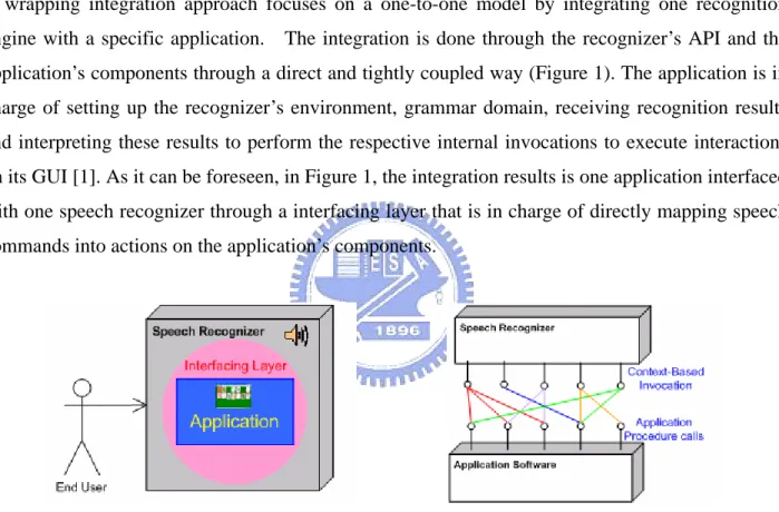
(13) approach, interaction commands can be dynamically scripted to simplify user interaction and allow more natural speech commanding.. 1.2. Current Recognizer Integration Methods. Currently at least two approaches have been used to interface speech recognizers with application software. Bellow we point out the main features of these two approaches.. 1.2.1. Wrapping Integration Approach. A wrapping integration approach focuses on a one-to-one model by integrating one recognition engine with a specific application. The integration is done through the recognizer’s API and the application’s components through a direct and tightly coupled way (Figure 1). The application is in charge of setting up the recognizer’s environment, grammar domain, receiving recognition results and interpreting these results to perform the respective internal invocations to execute interactions on its GUI [1]. As it can be foreseen, in Figure 1, the integration results is one application interfaced with one speech recognizer through a interfacing layer that is in charge of directly mapping speech commands into actions on the application’s components.. Figure 1. Wrapping Integration. Most of speech-driven robots adopt such interfacing approach for its design and implementation. Such is the case of AT&T’s Speech-Actuated Manipulator (SAM) [2] that understood spoken commands via telephone and performed the respective actions. Such complex machines must adopt a wrapping integration approach do to the uniqueness that they present in their non standardized internal system that most of the times differ amongst robots. Under such a tightly coupled-system, it is not surprising that any modifications on the low level application software’s commands will result in the recoding of the speech interface, leading to the recompilation of the whole system.. 2.
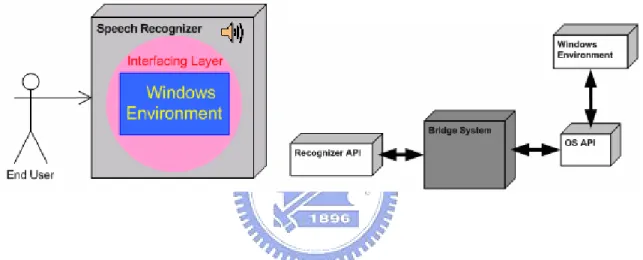
(14) 1.2.2. OS Integration approach. An OS integration approach focuses on a one-to-many integration by integrating one recognition device to an Operative System’s windows environment where applications reside. In a similar way to the wrapping integration approach, the integration is done through the recognizer’s API and the bridged system’s internal components. This approach adds a reference layer by interfacing applications through the Operating System’s API that performs simplistic actions on a focused windows environment where application’s GUIs belong. In this way interfacing and interacting directly with the operating system allowing it to respond through interactions with applications of its windows environment. Allowing one speech recognizer to interact with the domain of applications contained in a windows environment at a given time (Figure 2).. Figure 2. Windows Environment Integration. Current Solutions Three application systems Vspeech 1.0 [3], Voxx 4.0 [4] and IVOS 2.0.1 [5] that utilize an OS integration approach where chosen for discussion to provide a clearer view on how current solutions are designed and what features they provide to users.. Voxx 4.0 Voxx 4.0 [4] is a speech recognition program that incorporates dictation and voice commands for the windows environment. Its main features include: (1) Window manipulation and menu navigation through voice commands (2) Document and application opening through simple shortcut words (3) Custom shortcut creation To accomplish menu navigation, Voxx invokes OS API parsing functions to retrieve identification of objects present in the windows environment. These Identifiers are used to build the dynamic. 3.
(15) interaction vocabulary for the speech recognizer. When any recognition occurs, it invokes the OS API functions that perform native actions on the recognized identifiers. Figure 3 shows the shortcut list displayed to the user that is used for viewing the current recognition domain.. Figure 3. The Voxx 4.0. VSpeech 1.0 VSpeech 1.0 [3] is a speech recognition program that incorporates dictation and voice commands in the same fashion as [4]. It differs in the following: (1) Internet “link” Navigation Support for Microsoft’s Internet Explorer (2) Lacks user-shortcut definition VSpeech functions just like Voxx, presenting a listing of words that represent the current content that can be spoken to invoke actions on the windows environment (Figure 4). Unlike Voxx, VSpeech adds URL links found on focused IE browser to the recognition list, so that they can be accessed by speaking their reference name.. 4.
(16) Figure 4. The VSpeech 1.0. IVOS 2.0.1 IVOS 2.0.1 [5] is also another speech recognition program that incorporates dictation and voice command capabilities. It differs from VSpeech and Voxx in the following ways: (1) Extends shortcut commands functionality by allowing the user to register synonyms to execute the same actions with different vocabulary (2) Introduces VoiceTouch technology that enables the computer to learn routines performed by the user as he interacts with the system. This enables routine repetition if needed by the user.. IVOS is a more advanced solution when compared to VSpeech and Voxx, since it introduces a mechanism that simplifies interaction by allowing repetitive tasks to be done by the system. Also it shows signs of a more flexible interaction environment, allowing different vocabulary for referencing the same content. Although it adds extensibility, it does not tackle most of the common limitations that are found in speech-recognition applications. Moreover, the interaction environment imposed to the user compares in a close range of constraint with current solutions even though it attempts to provide a more friendly interfacing mechanism. Figure 5 depicts the outlook of the IVOS interaction environment.. 5.
(17) Figure 5. The IVOS 2.0.1. 1.2.3. Challenges and Limitations of Current Recognizer Integration. Limitations suffered by the current integration approaches mostly result from the direct tightly-bind integration of a speech recognizer with either an application or a window’s environment. The following challenges and limitations exist in current approaches: ‧ Non-Generic: – Current approaches leave no flexibility for future modifications – Current approaches lack a generic recognizer interfacing system that can truly coexist with more than one application environment – Current approaches lack a graphic interfacing environment that interfaces application’s buttons, containers and menu items ‧ Complex: – Current approaches focus on recognizer integration through the back-end of applications requiring low-level programming and system design knowledge. ‧ When integrating applications, the interfacing process to bind recognition results to internal application actions must be redesigned each time ‧ Modification of application’s interfacing environment require re-compilation of source code. 6.
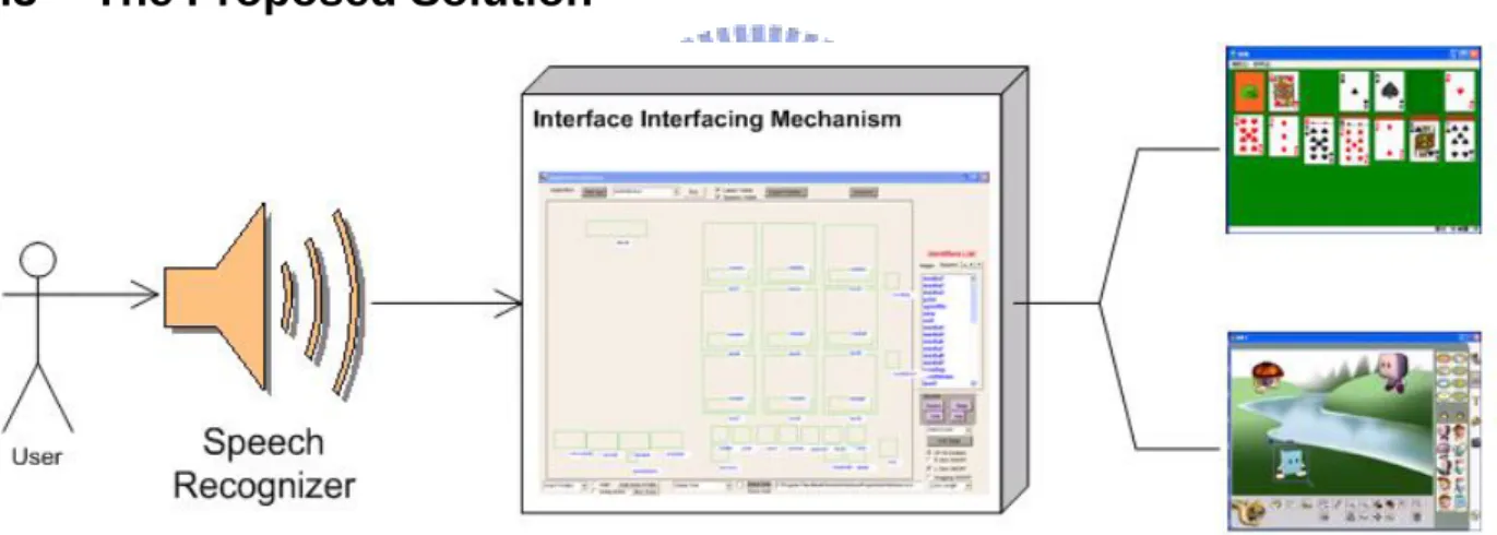
(18) ‧ Non-Customizable: – Current approaches’ tightly coupled system design does not allow the customization of the interaction environment by the user ‧ Allows modification of the vocabulary used for speech only – Current approaches do not efficiently separate and handle recognition context ‧ Inefficient: – Lacks of a post-interfacing mechanism to abstract a group of actions into single commands to minimize user interaction tasks ‧ Interaction is based on a “One spoken command yields to execution of one hard-coded Action"basis. 1.3. The Proposed Solution. Figure 6. The Proposed Interfacing Approach. Our approach consists of an application-independent visual interfacing environment generator to bridge a speech recognizer with applications’ front-end (Figure 6). In our approach, to incorporate speech recognition to applications, a user through our system composes a visual interfacing environment by drawing reference zones on top of applications’ GUI’s interactive areas, without the need of programming the integration. User-generated visual interfacing environments for applications are interacted with by the system as it processes user’s requests to perform interaction on the environment’s zones that are graphically positioned over interaction objects of applications. Our approach is an improvement of an OS integration approach. The proposed system interacts with target applications by performing invocations to the Operating System’s API that then manipulates 7.
(19) its input-device and window environments to perform interactions directly on the visual interfacing environment that lays above target applications. Our approach aims to tackle current challenges and limitations of recognition integration to applications by providing:. Generic Interfacing: -Fitting more than one application environment -Allowing simultaneous interfacing content handling for multiple applications resulting in easy application swapping by simply loading the corresponding interfacing profiles that belong to an application.. Flexibility: -Adopting Front-End custom interfacing through a transparent reference layer -Developing an interfacing visual environment that allows users to define their specific speech-driven visual environment through the application’s front end without doing any low-level programming tasks. -Allowing visual modification of interfacing content during runtime with out affecting other application’s recognition interfaces, and without the need of recompilation of application’s source code to make changes take effect.. Efficiency: -Integrating a language definition that allows the interaction with the visual interfacing environment through spoken commands and that also facilitates composition of macro commands by users to wrap complex and lengthy tasks into single context-free reusable commands, increasing speech recognition efficiency and approximating the way to speak to a more natural one, with out utilizing long and complex sentences to accomplish multiple tasks at once.. Our approach also aims at supporting user interaction with dynamic content of applications during run-time by keeping track of these entities and their different states as the user interacts with them.. 8.
(20) 1.4. Thesis Organization. The organization of this thesis is divided into two discrete parts. The first part focuses on the challenges present in current approaches and focuses in the foundations that will allow overcoming these challenges. The first chapter is concerned with the importance of the challenges for current recognizer interfacing technologies and how these challenges motivate our study. Chapter Two reviews the technologies involved in this study that are considered for tackling the challenges found in current interfacing solutions. The second part of the study is concerned about the design and implementation of the proposed system. Chapter Three introduces the aspects of our proposed solution and provides a low-level detailed system architecture design context on how our approach was designed from the bottom up. This Chapter then goes into how the different entities that result from the system architecture design interact whit each other and what interaction steps are taken by these entities to achieve the common goal of setting up a visual interfacing environment and provide a successful interaction with the target application. Chapter Four consists of the definition of the language that is incorporated to our system. Chapter Four un-wraps every aspect of the designed language, its data types, rules, syntax description, and the interpretation steps involved in command processing. This is followed by a detailed analysis and qualitative evaluation of the system in terms of the specific criteria identified for the successful development and deployment of the proposed system in Chapter Five, by setting up and performing common interfacing and interaction scenarios. Chapter Six concludes the paper and offers suggestions for future research. The reference appendix consists of the listing of previous work referred to and/or referenced in this study. Appendix I consists of the speech-engine’s grammar definition that mirrors that of our designed language. Appendix II consists of our system’s language definition in BNF format.. 9.
(21) CHAPTER TWO Related Technologies Used for the Development of the Interface Interfacing Framework 2.1. Introduction. Creating a successful recognizer interfacing system is dependent on several technologies. These technologies individually belong to different fields of study, however when implemented in a cooperative environment, these technologies merge to contribute towards the vision of Interface Interfacing. This chapter goes into detail about each of the technologies involved in the development of the interface interfacing framework, and gives views of related works for a deeper understanding of each.. This chapter serves as the foundation of the overall technological. background involved in this study and provides a brief overview of the proposed solution and how it incorporates these technologies.. 2.2. “See-Through Interface” Paradigm. In our work we use the “See-Through Interface” paradigm to construct the visual interfacing environment that allows application front-end integration with recognizers through the drawing of reference zones. The “See-Through Interface” paradigm [6] focus on interfacing tools that appear as a transparent sheet of virtual glass called “Toolglass” between an application and a traditional mouse cursor. These interfaces provide additional views of application objects. The “See-Through” interface provides a new style of interaction that better exploits the user’s every day skills. They can be used to reduce steps, cursor motion and errors; moreover they do not require dedicated screen space since they lay on top of the application. These interfaces provide rich context-dependent feedback and the ability to view details and context simultaneously. These widgets [6] can be combined to form operation and viewing macros to simplify use. This paradigm provides mechanisms to draw grids on applications to reference zones that may need this type of guidance, such as drawing panes, or object selection screens.. An application may use many views that require more than one “see. through interface”, for this a managing system is presented to load the corresponding transparent interfaces of each screen, in this way shifting Toolglasses depending on the application content.. 10.
(22) The “See-Through Interface” parading is adapted to many research areas. In [7], the authors create an immersive environment that submerges users into a virtual space, effectively transcending the boundary between the real and the virtual world. This virtual 3D world can be manipulated by the user without the need of relaying on traditional input devices such as the mouse and keyboard for interaction. This study adapts a bimanual gesture interpreter and parser that recognizes and translates the user’s arm motions to commands that invoke actions on a “Toolglass” based transparent interface that lays above this 3D environment (Figure 7). The transparent Toolglass interface paradigm is adapted as a gesture interface widget for spatially immerse environments. The user is physically surrounded by this environment as it is projected on walls of a room like structure where the user stands in the middle and uses hand gestures to move the transparent interface to the different locations of the environment to interact and view information of application objects without the need of intermediate hardware such as gloves, 3D-Mouse, or VR headgear. Actions are executed by clicking through one of those wedges, and the action is applied to the object directly behind the Toolglass.. Figure 7. The 3D Visualization and Manipulation in an Immersive Space. Another work where the “See-Through Interface” paradigm is adapted is Collaboration Transparency in the DISCIPLE Framework [8]. In this work a framework to share collaboration-transparent single-applications is developed. To share these applications, a conference agent is placed between the application’s GUI and the Windows System (Figure 8). The conference agent intercepts the user input events by adopting a special transparent Toolglass interface to intercept the events destined for the shared application window.. 11.
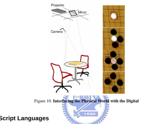
(23) Figure 8. The Conference Agent Interfacing. This top-down approach intercepts all the user events (mouse, keyboard, input focus events) using a transparent GUI component without occluding the under-laying applications (Figure 9). Each time an event gets intercepted by the glass-pane, it is dispatched by the agent to the target application object. Such transparent pane is used to filter unwanted invocations to application objects in a collaborative environment when two or more users may be sharing a single application at the same time and such interaction may create conflicts.. Figure 9. Transparent Interface. Futuristic approaches such as Parsimony & Transparency in Ubiquitous Interface Design [9] focus on transparently integrating aspects of the digital world into real life artifacts, by providing ubiquitous interfaces to computation that do not obscure the highly redefined interaction modalities of the host artifact in the physical world. Coexistence of the physical and the digital worlds leads to more learnable interfaces. Here a Toolglass like interface is projected upon real life objects (Figure 12.
(24) 10), and it is used to mark the status of the objects during time. A board game is chosen in the study as the physical environment to interface, adding features to the classic game such as game recording and automatic move clock without altering the physical environment. These interfaces, like Toolglass based ones provide different views and information about the interfaced objects attributes when interacting with them physically.. Figure 10. Interfacing the Physical World with the Digital. 2.3. Script Languages. In our work we apply script languages to enhance interaction efficiency through the definition and use of macro commands that allows abstraction of actions into single context-free reusable commands. Scripting focuses on connecting diverse pre-existing components to accomplish a new related task [10]. Those languages which are suited to scripting are typically called scripting languages. Script languages are viewed as the "glue" that puts several components together; thus they are widely used for creating and interacting with graphical user interfaces. Scripts are typically stored only in their plain text form (as ASCII) and compiled each time when they are invoked. A scripting language controls the operation of a normally-interactive program, giving it a sequence of work to do all in one batch such as a macro, storing a series of editing commands in a file, and telling an editor to run that "script" as if those commands had been typed interactively. Script languages generally have the following properties: • •. Source code is present at run time in production system. Use of an interpreter or VirtualMachine is generally required.. 13.
(25) • • •. Variables, functions, and methods typically do not require type declarations. There are automated conversions or equivalence between types. The ability to generate, load, and interpret source code at run time through an eval function. Interface to the underlying system components, in order to run other procedures and communicate with them.. In [11], Koong utilizes EDBL (Electronic Book Description Language) script language to hold electronic book projects description files. An interpreter is used along a playback system to present the multimedia effect of authored scripted documents that when processed result in the playing of the final presentation by having the interpreter interpret the description commands found in the script file dynamically. The playback system then executes the associated actions based on the interpretation results of the script instructions.. The language specification of the designed script language for this study is highly influenced by the Java Language Specification [12] to establish its syntactic rules; its design is simple enough to allow programmers to quickly achieve fluency in the language. Unlike Java that is strongly typed by distinguishing between compile-time errors and the ones that occur at run-time, our language design is based on Just-In-Time compilation by compiling the code as necessary, running it in an interpreted framework [13]. In this way code that is not executed does not get compiled, assimilating our language more to a console command language, but however integrating macro composition functionalities that also allow our language to behave as scripted. Our language approach is very simplistic, being a script language that does not focus on creating objects or maintaining class-like structures but instead interpreting batches of commands. WinBatch [14], a commercially available high-level macro scripting language takes a similar approach, by designing a language that provides batch automation for Windows systems by allowing users to compose macros that are interpreted utilizing Just-In-Time compilation to automate PC management, business processes, network administration tasks, and overall system use in order to relax the user’s interaction overhead. WinBatch accomplishes the above by interfacing directly to the operative system’s underlying system components to communicate and run procedures involved in the automation of user’s tasks.. 2.4. Speech Recognition Engines. Speech Recognition is not a new entity. It first evolved over 30 years ago (Stevens, 1960). This continued growth in technology opened the doors to various applications of Speech Recognition. Speech Recognition not only became a popular medium for use by professionals in the working 14.
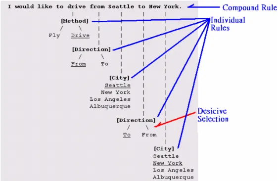
(26) world, but also an exceptional tool for people with disabilities [15]. Features of Speech Recognition systems have progressively advanced over the last 35 years. Initially, in 1972, dictation and word processing systems were combined to formulate the first Speech Recognition system (Lange, 1993; Meisel, 1993) [15]. At this point, systems could only handle discrete speech dictation where pauses between every word spoken were required for the signal to be processed. Today, it is difficult to find any programs that still use discrete speech; most programs have the capacity to handle continuous speech where the speaker talks naturally, without the need to pause between every word. Speech applications often use context-free grammars (CFG) to parse the recognizer output and in some instances, to act as the recognizer's language model, Speech recognition engines use CFGs to constrain the user's words to words that it will recognize [16]. CFG is based on grammatical rules that are meant for proper recognition of words. Speech recognition grammar provides the interface of the speech recognizer to the corresponding operations that take place at the target application at the moment of interaction. Complex grammar definition is achieved by organizing rules into hierarchical structures, allowing higher level rules to be composed of references to lower-level rules. Phrases and sub-expressions are represented by separate rules and combined together to form complete sentences. When interpreting a rule decisive selection can be applied to provide a more flexible way of speech and avoiding rules re-definition. Rules restrict the word choices during the recognition process. Applications that are interfaced with speech recognizers listen to context or events that are triggered when a rule is recognized. Depending on the context, the applications takes the corresponding actions, speech recognition engines only handle the recognition job. Phrases spoken use each grammar rule element to determine the recognition path (Figure 11) by traversing the grammatical rule structure.. 15.
(27) Figure 11. A Recognition Path Example. Applications should separate dynamic rule content from static rule content to implement good grammar design and to improve grammar compiler performance. Applications could create a separate rule (isolated in its own grammar) that contained only the static rule content, then the static grammar would contain a rule reference to the dynamic content.. The chosen speech recognizer for this study is Microsoft’s Speech-Recognizer V.6.1. [17]. This recognizer contains two different types of speech recognition engines, which are the ISpRecognizer type that is shared amongst several applications by instantiation and the InProc type which is focused for performance hungry applications in which each application has its own ISpRecognizer[16]. In this study the ISPRecognizer type engine is used. Grammar definition for the Microsoft’s Speech-Recognizer is CFG rule-based. A special component of the system was chosen to directly interface the speech recognition engine, this component handles recognized context and distributes it to the rest of the system for further processing to eventually interpret it into actions on the application’s interfacing environment. The interfacing component is the only entity in the system that presents a tightly coupled binding with the speech recognition engine as it is integrated into the component through calls of its API to provide a manipulation interface of the recognizer to the rest of the system.. 16.
(28) 2.5. Conclusion. This chapter presented an overview of the foundation technologies required to base an interface interfacing study on. This chapter provided an insight into the technological needs for the implementation of an environment that tackles the current challenges stated in the previous chapter and how each of these technologies contribute towards the vision of Interface Interfacing. Chapter Three introduces our proposed approach and goes into high detail on the entities that compose it and how they behave with one another to accomplish a common goal of enhanced interfacing with target applications.. 17.
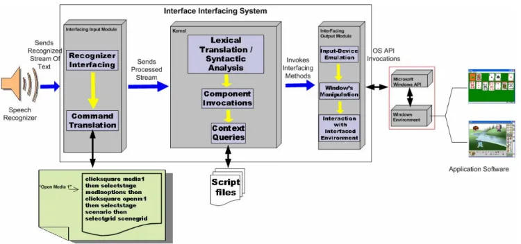
(29) CHAPTER THREE System Architecture Design and Implementation of the Proposed Interface Interfacing Framework 3.1. Introduction. This chapter introduces the proposed system, the Interface Interfacing Framework. The system is discussed in great detail from a high to low level viewpoints to provide a complete view of the system from various perspectives. Focusing on the modules that compose the system and in what way each of them is responsible of providing an overall interfacing of a target application with a recognizer.. 3.2. The Interface Interfacing Framework. The proposed system interacts with target applications by performing invocations to the Operating System’s API that then manipulates its input-device and window environments to perform interactions directly on the system’s “Transparent Interface” that lays above target applications. It adapts the “ See-Through Interface " Paradigm to support Front-End custom interfacing of applications, in this way allowing visual modifications to the interfacing environment without the need of recompilation of source code. Our approach integrates a script language that allows real-time interaction through commands with the interfacing environment of an application and also facilitates composition of macro commands by users to wrap complex and lengthy tasks into single context-free reusable commands. The system is designed in a modular way by adapting specialized entities, such as the recognizer interfacing component that integrates a speech recognizer and allows localized integration of future recognizers through modifications on this component while leaving the rest of the system intact. The overall system architecture of the proposed Interface Interfacing Framework is depicted in Figure 12.. 18.
(30) Figure 12. The proposed Interface Interfacing System. The interfacing of recognition devices and applications is done through two different interfacing layers that interact directly with the system’s kernel (Figure 12). The Interfacing Input Module is in charge of interfacing with recognizers and processing recognized content into a format compatible with the system. The processed stream is sent to the Kernel where the parsing and interpretation of commands take place, here a central invocation mechanisms, delegates invocation requests for the Kernel to the components of the Interfacing Output Module that are the ones that interact directly with the Interfacing Visual Environment to provide interaction with the target application by manipulating the window’s environment and emulating input device interactions. To develop our proposed system we took a service-oriented approach by distributing individual services to subsystems of our solution to later proceed with the integration of these, to provide a robust, flexible and modular design. In the following subsections, we elaborate the details of each module inside the proposed Interface Interfacing Framework.. 3.2.1 Interfacing Input Module The main function of the Interfacing Input Module is to interface the system with recognition devices, handle the interfacing, setup and initialization of these, retrieve recognition content and process it by translating it into a format compatible with the system’s language commands definition.. 19.
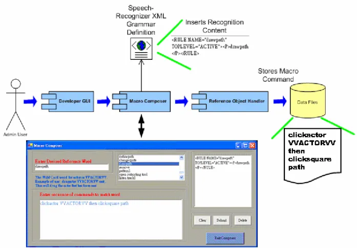
(31) 3.2.1.1 Interfacing Input Module Components. Textual Command Receiver In charge of retrieving the content recognized by the Speech Recognizer, including the commands that are spoken by the users, communicating the recognized streams to the Language Translator, those are the main task of the Textual Command Receiver. In this research, the Microsoft’s Speech-Recognizer V.6.1 [17] was chosen as the target speech recognizer. The interfacing was done through the speech engine’s Standard Developing Kit (Microsoft’s Speech SDK V.5.1) through API calls on the Textual Command Receiver.. Language Translator The language translator takes care of translating the spoken text to the language that is understood by the internal system. Once the translation is completed, it passes down the translated text to the Macro-Interpreter component.. Macro-Composer/Interpreter The Macro Composer/Interpreter is in charge of providing the mechanism of macro command composition by allowing the user to wrap sequences of commands in the system’s internal language into single reusable macros. This component interprets macros recognized by the speech recognizer by loading their corresponding code into the system.. Wildcard-Translator The Wildcard-Translator takes care of replacing wildcards found in macros with the identifiers of currently focused interfacing objects. In this way, it provides a generic and context-free command composition environment.. 3.2.1.2 Macro Command Registration and Interpretation. Although interacting with the proposed system by speaking commands according to the syntax provided by the defined language is possible, it requires a high learning curve and overall interaction may be degraded.. The system contains a mechanism that allows for the composition of. macro commands that are used to perform complex tasks through the invocation of single and reusable commands. The macro commands are defined using the system’s internal language and add an extra layer of abstraction but simplifying the user interaction. 20.
(32) The registration of macro commands (Figure 13) takes place at the Developer GUI component where the user composes the macros and assigns them a referenced identifier (“keyword”). During the composition of a macro command a XML structure is dynamically created for speech recognition purposes. When the macro is submitted, the Macro Composer inserts this XML structure into the speech recognition engine’s grammar definition so that a reference to the macro can be successfully recognized when spoken, achieving immediate speech recognition of macros as they are composed.. In this way, acting as a black-box mechanism, transparent to the user and. avoiding the use of an external XML editor to add recognition of macros to the recognizer. The macro command itself gets stored to file through the Reference Object Handler. When a macro command’s reference keyword is spoken, the macro is loaded from file and executed as a regular set of commands would.. Figure 13. Macro Composer/Interpreter. 3.2.1.3 Interfacing Input Module Processes. Whenever the speech recognition engine recognizes spoken phrases, it outputs those phrases as 21.
(33) text streams in the spoken language, according to its XML Grammar Definition. The stream of text is then passed down to the Language Translator Component where the first translation takes place. The Language Translator breaks the stream of text into single words, and queries word by word for a corresponding match in the Language Translation Resource to translate them to their corresponding value in the system’s language. Once all the phrases are translated to the system’s native language, the second translation of the process takes place. The Macro Interpreter receives the stream of text and checks if the stream of text contains keywords that identify macro definitions, it does so by querying the Macro Data Repository for matches. If a match is found, the keyword inside the stream of text gets replaced with the one found. Once a macro is loaded, it is passed down to the Wild Card Translator that checks for the presence of wildcards, replacing any found with the identifier of the interfacing object that currently has focus.. Figure 14. Command Translation Process. 22.
(34) In Figure 14, the macro command “draw path” gets translated into its corresponding system’s language format, replacing its wildcards with the actor that currently holds focus.. 3.2.2 Kernel Module The main function of the Kernel Module is to interpret commands into system actions through invocations on components that interact directly with the interfacing environment. The Kernel Module is in charge of delegating and moderating invocation traffic through a centralized component to entities that interact with the “See-Through Interface”. The Kernel Module is also in charge of handling the loading, storing, tracking, and activating objects of interfacing content. We design a script language that allows real-time issuing of commands to our system and its rules are used by this module to interpret commands. The language definition is explained in details in Chapter 4.. 3.2.2.1 Kernel Module Components. Lexical Translator The Lexical Translator is in charge of receiving a stream of commands from the Macro Interpreter and breaking it into token sets, each token set represents a command that is sent to the Syntactic Analyzer for interpretation and validation in a token set per token set basis.. Syntactic Analyzer It receives token sets from the Lexical Translator one set at a time, and processes them by checking their syntactic meaning against the grammatical rules by parsing a syntactic structure and validating any undefined variables found in the tokens. Depending on the parsing path, it produces the target program that consists in invocations through the Event Driven GUI on components that interact with the interfacing visual environment.. Interfacing Object Reader/Writer This component is in charge of storing, retrieving and performing the object activation of the different interfacing objects that are used for building a visual interfacing environment of an application. It is also in charge of handling dynamic interfacing content and providing the tracking mechanism to re-locate them whenever a user interacts with them. This component is subdivided into two parts: -Application/Actors/Stages/Grids Handler 23.
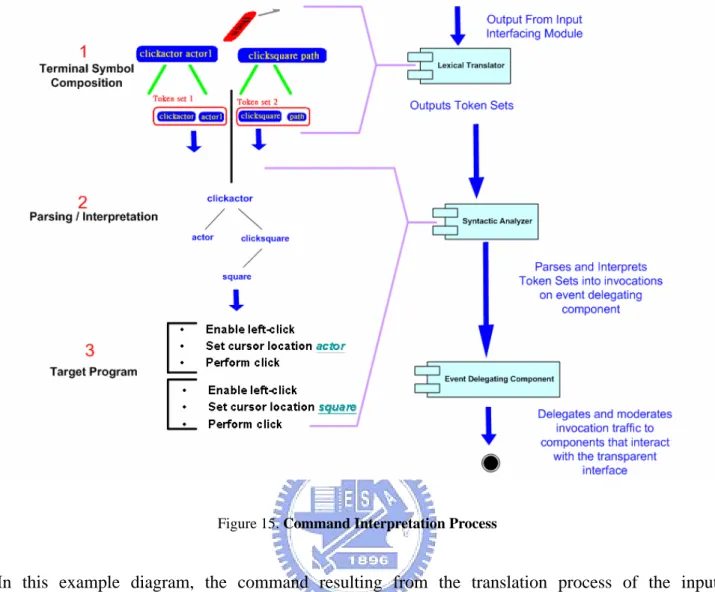
(35) Handles the loading and storing of objects of type application, actor, actor profile, stage and grid and keeps track of the location of dynamic content such as actors.. -Square Mapping Mechanism Handles square loading and registration by storing each square’s graphical information and identifier into individual files under their corresponding stage directory.. Event Driven GUI (Event Delegating Component) The Event Driven GUI is the centralized component that delegates and moderates invocation traffic that results from the command interpretation process into components that interact with the interfacing environment, in this way acting as a proxy.. 3.2.2.2 Kernel Module Interpretation Process. Translated commands that result from the Interfacing Input Module process are sent to the Kernel so that they can be interpreted into a target program (Figure 15) that provides the interaction with the interfacing environment. As the stream of text enters the kernel, the Lexical Translator splits the stream of text into token sets. Each token set represents a single command that is fed down to the Syntactic Analyzer for interpretation. When the Syntactic Analyzer receives a token set, it analyses it token by token and traverses the parsing structure until a match of a valid command with a compatible format is found. Once the parsing is successful, the corresponding target program is executed at the Event Delegation Component (Event-Driven GUI) and the later delegates the invocations to the respective system components.. 24.
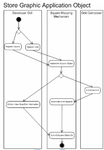
(36) Figure 15. Command Interpretation Process. In this example diagram, the command resulting from the translation process of the input interfacing module (“clickactor actor1 then clicksquare path”) is broken down into two token sets that are interpreted into the target program depicted above. 3.2.2.3 Kernel Module Interfacing Object Handling. The Kernel Module is also in charge of loading, storing, tracking and performing the object activation of interfacing content. To store a graphic object (Figure 16), it involves the drawing of the reference zone at the Developer GUI. Once the request is made, the Square Mapping Mechanism instantiates the object. If the object is of grid type, the Grid Composer component is invoked to automatically compose a grid by creating several squares that later get instantiated and submitted to the storage repository through the Square Mapping Mechanism. If the object is of type square, the user specifies its name and other information back in the Developer GUI witch then invokes the Square Mapping Mechanism once more to submit the graphic object.. 25.
(37) Figure 16. Storing Graphic Application Objects. The registration of a non-graphic application object (Figure 17) can be made directly from the Developer GUI, by interacting with the controls of the desired object type, triggering the instantiation of the object type in the Application Handler component. If the object to be stored is of a type that requires automatic creation (grids, actors, actor profiles) then the system handles the specification of its information, otherwise the user specifies this information at the Developer GUI component during the registration stage and requests the submission of the object to finalize the process. The Syntactic Analyzer also interfaces with any of the methods used to store application objects at the Developer GUI so that they can be executed through speech.. 26.
(38) Figure 17. Storing Non-Graphic Objects. A request to delete an object (Figure 18) can be made directly from the Developer GUI, by interacting with the controls of the desired object type. The Square Mapping Mechanism component then takes care of parsing the object storage files and removing any information that corresponds to the selected object. The Syntactic Analyzer also interfaces with any of the methods used to delete application objects at the Developer GUI so that they can be executed through speech.. Figure 18. Deleting Application Object. Reference interfacing objects such as squares, grids, stages, actor profiles and actors are stored-retrieved and modified dynamically into and from a 4-level hierarchical directory structure (Figure 19). 27.
(39) Figure 19. Interfacing Objects Hierarchical Organization. 3.2.3 Interfacing Output Module The main function of the Interfacing Output Module is to provide the mechanisms to interact directly with the front-end of the application through the Interfacing Visual Environment by performing input-device emulation and window’s environment manipulation. This module adopts the “See-Through Interface” paradigm to provide the tools that are used to compose the Interfacing Visual Environment and macro commands. 3.2.3.1 Interfacing Output Module Components. Developer GUI(Graphic User Interface) Component targeted at the composition of the customized Event-Driven Visual Interfacing Environment. The “See-Through Interface” Paradigm is adapted to allow users to visually establish reference to buttons, containers or other context inside the target application. Through this component, zones of the target application can be interfaced by drawing referencing zones such as squares and grids on a transparent frame, organizing the context through non-visual referencing by defining Actor Profiles and Stages. A labeling system is developed to visually label each of the registered reference zones at their graphic location with its registered identification name. Figure 20 depicts an application in its natural state, while Figure 21 depicts the application’s corresponding visual interfacing environment composed of interfacing objects. 28.
(40) Figure 20. Unreferenced Application. Figure 21. User Referenced Application. Grid Composer The task of this component is to create grids. It creates individual square objects and later returns a collection of them that form the grid, labeling each square with coordinates so that the user can identify each of them individually.. 29.
(41) Mouse AI (Input Device Controller) In Charge of manipulating input devices to perform mouse or keyboard related actions on the Interfacing Visual Environment is the Input Device Controller. This component takes care of emulating the following mouse actions: -Left_Mouse_Click -Left_Mouse_Double_Click -Right_Mouse_Click -Right_Mouse_Double_Click -Drag_and_Drop -Move. Additional features such as moving the mouse cursor in any possible direction and speed, predefined movement-patterns and virtual keyboard implementation are also incorporated in this component. External App Manager (Window’s Environment Handler) The main task of this component is to manipulate the window’s environment by capturing windows, their child and applications inside a container to modify their size and perform any other tasks needed for interacting with the Interfacing Visual Environment. This component interacts directly with the operative system’s API to accomplish the above.. 3.2.3.2 Interfacing Output Module Processes. Target programs that result from the syntactic analysis are executed through the Event Delegating Component. Depending on the command, the requests for each of the involved events is sent to corresponding components that interact directly with the interfacing environment. These interacting components can also interact with each other by delegating requests amongst them to satisfy a command request. Commands depending on their magnitude could trigger an exponential growth in the number of system-internal calls needed to serve a request or might as well achieve completeness through a single invocation. A more detailed view on invocations is discussed in section 3.6.. 30.
(42) Figure 22(a). Visual Interfacing Environment Interaction. Figure 23(b). Visual Interfacing Environment Interaction. In Figures 22, the target program is executed by first enabling left click emulation at the Input Device Controller(1), then the cursor is set to the location of the specified actor that is retrieved by. 31.
(43) the Object Reader component(2) and lastly a click is performed by the Input Device Controller(3). The same process is repeated for clicking the specified square.. 3.3 Design Patterns Throughout the design of our system, Object-Oriented design patterns [18,19] where taken into consideration to provide a more organized and efficient system interaction. Following are the design patterns that we took into consideration for this study.. 3.3.4 Facade Design Pattern. Figure 24. Facade Design Pattern. The facade pattern (Figure 23) can make the task of accessing a large number of modules much simpler by providing an additional interface layer. When designing good programs, programmers usually attempt to avoid excess coupling between module/classes. Using this pattern helps to simplify much of the interfacing that makes large amounts of coupling complex to use and difficult to understand. This is accomplished by creating a small collection of classes that have a single class that is used to access them, the facade [18]. In our system a facade approach is used, where the Event Driven GUI component is used as this interface layer that acts as the “bridge” to access all of the under-laying modules. The Syntactic Analyzer module acts as the client that requests services from modules through the Event Driven GUI. A double facade effect occurs in our system in the sense that the Square Mapping Mechanism module itself acts as a facade that delivers requests from the Event Driven GUI that is a facade as well. The primary advantage of using the facade is to make the interfacing between many modules or classes more manageable and organized [19].. 32.
(44) 3.3.5 Interpreter Design Pattern. Figure 25. Interpreter Design Pattern. The Interpreter Design Pattern (Figure 24) focuses on defining a macro language and syntax, parsing input into objects which perform the correct operations desired [19]. In our system, a language definition exists, and the above design pattern for language interpretation is applied. The Interpreter Design Pattern is present at different levels; the first interpretation is done at the Macro Interpreter, to check if the spoken word is a keyword of a macro command, if it is it gets translated to our defined language. The Lexical Translator breaks this phrase into token sets and feeds it to the Syntactic Analyzer, acting as the client. The Syntactic Analyzer then acts as the Interpreter of the language, by representing phrases according to the defined grammar and performing the set of invocations to procedures through our earlier discussed facade mechanism that reaches a set of worker classes that will take care of performing individual operations of the composed command.. 3.3.6 Proxy Design Pattern. Figure 26. Proxy Design Pattern. 33.
數據

+7
相關文件
The prototype consists of four major modules, including the module for image processing, the module for license plate region identification, the module for character extraction,
語文運用 留意錯別字 辨識近義詞及詞語 的感情色彩 認識成語
圖形使用者介面( graphical user interface GUI). 圖形使用者介面( graphical user
應用閉合電路原理解決生活問題 (常識) 應用設計循環進行設計及改良作品 (常識) 以小數加法及乘法計算成本 (數學).
•比起單調地教授語音知識,不同的聽、説 活動更能激發學生學習的興趣,如把語音
在軟體的使用方面,使用 Simulink 來進行。Simulink 是一種分析與模擬動態
如圖 4-22 IBM Via Voice 語音辨識軟體與 Visual Basic 機器人程式只是一個互 助的關係,Visual Basic 無法控制 Via Voice,Via Voice
系統精準度為 FALCON 系統學習完後之學習精確率,驗證組之平 均精度為系統經驗證組驗證後之系統精確率。上表 5-2 中 Case A、Case B 及 Case
