國 立 交 通 大 學
電信工程研究所
碩 士 論 文
分時全雙工之正交分頻多用戶系統於非
對稱服務環境下之跨時槽干擾分析
Cross-Slot Interference Analysis for
TDD-OFDMA Systems with Asymmetric
Services
研究生:李偉齊
分時全雙工之正交分頻多用戶系統於非對稱服務環境
下之跨時槽干擾分析
Cross-Slot Interference Analysis for TDD-OFDMA Systems
with Asymmetric Services
研 究 生:李偉齊
Student:Wei-Chi Li
指導教授: 王蒞君 Advisor:Li-Chun Wang
國 立 交 通 大 學
電信工程研究所
碩 士 論 文
A ThesisSubmitted to Institute of Communication Engineering College of Electrical and Computer Engineering
National Chiao Tung University in partial Fulfillment of the Requirements
for the Degree of Master of Science
In
Communication Engineering July 2010
Hsinchu, Taiwan, Republic of China
分時全雙工之正交分頻多用戶系統於非對稱
服務環境下之跨時槽干擾分析
學生:李偉齊
指導教授:王蒞君 教授
國立交通大學
電信工程研究所
摘要
在本篇論文中,我們在支援非對稱服務的環境裡,探討了部分頻率重
覆使用 (Fractional Frequency Reuse, FFR) 機制在分時雙工且正交分頻多
工 存 取 (Time Division Duplex-Orthogonal Frequency Division Multiple
Access, TDD-OFDMA) 系統中所能獲得的好處。並討論如何應用部分頻率
重覆使用機制來降低相鄰細胞間的同頻干擾 (Inter-Cell Interference) 並維
持頻譜使用率 (Spectrum Efficiency)。然而,我們提出了一套分析的方式來
分析跨時槽範圍 (Cross Time Slot Region, CTS Region) 與設計部分頻率重
覆使用機制參數之間的關係。這套分析的方是主要是應用排隊理論原理
(Queuing Theorem) 並且考慮通訊傳輸系統中的每一位使用者 (Mobile
Station, MS) 使用情形,來進一步計算出發生跨時槽範圍的機率。如此一
來,能透過這套分析的方法來幫助我們在支援非對稱的環境中,適當地設
計部分頻率重覆使用機制所使用的參數。
輸入多輸出天線系統 (Multi-Input and Multi-Output Antenna, MIMO) 和部
分頻率重覆使用機制…等等。據我們所瞭解,我們需要在未來的第四代
(Fourth Generation, 4G) 通 訊 系 統 中 使 用 更 多 的 頻 寬 來 達 到 高 傳 輸 率
(Transmission Rate) 的要求。然而,最有效換取更多頻寬的方式就是在每
一個基地台 (Base Station, BS) 的覆蓋範圍 (Cell Coverage) 中重覆使用相
同的頻譜。雖然,在每一個基地台重覆使用相同的頻率可以立即增加可使
用頻譜,但是卻會嚴重影響傳輸訊雜比 (Signal to Interference Plus Noise
Ratio, SINR)。然而,較差的訊雜比會影響到系統內使用者的連線品質
(Link Quality) 造就了干擾消除和頻譜使用率之間的難以取捨,也使得如何
在重覆使用頻譜的環境下依然可以維持良好的連線品質變成了一個很有
趣的議題。
為了維持良好的傳輸品質,我們必須謹慎的區分相鄰細胞間同頻干擾
的情況。在無線通訊系統中,主要有兩種雙工的模式可以用來區分上傳
(Uplink) 和下載 (Downlink) 的傳輸,也就是分頻雙工 (Frequency Division
Duplex) 和分時雙工 (Time Division Duplex)。在這兩種不同的雙工模式
下,會產生不同的相鄰細胞間同頻干擾的情形,尤其是在分時雙工模式並
且支援非對稱服務的環境下,更容易產生較強的相鄰細胞間干擾。這種特
殊的干擾量主要發生在跨時槽範圍內,也就是細胞間同時執行不同的傳輸
模式,而這種干擾量被稱為跨時槽干擾 (Cross-Slot Interference)。跨時槽
干擾主要可區分成兩種,分別為基地台對基地台的跨時槽干擾 (BS-to-BS
Cross-Slot Interference) 和 使 用 者 對 使 用 者 的 跨 時 槽 干 擾 (MS-to-MS
Cross-Slot Interference)。其中,基地台對基地台的跨時槽干擾會對系統效
能造成很嚴重的影響,特別是對於基地台較遠的使用者而言。
的非對稱服務的環境中。設計部分頻率重覆使用機制中的參數,可以同時
獲得提升頻譜使用率和降低相鄰細胞間干擾的好處。在本篇論文中,我們
探討了如何配置頻寬給不同區域的使用者、設計細胞內圈的大小和細胞外
圈的頻率重覆使用參數 (Frequency Reuse Factor)。此外,我們使用了一套
分析的方法來分析跨時槽範圍的大小和設計部分頻率重覆使用機制參數
之間的關係。更重要的是,我們可以應用這套分析的方法來找出最適當的
參數設定並且隨時更新設定,藉此改善現有系統所需的繁複計算和長時間
的模擬。最後,我們建立了一套應用部分頻率重覆使用機制在分時雙工且
正交分頻多工存取系統並支援非對稱服務的模擬平台,藉由此平台來找出
最適當的部分頻率重覆使用機制參數使系統傳輸量 (System Throughput)
最大並同時維持傳輸可靠度 (Link Reliability)。
Cross-Slot Interference Analysis for TDD-OFDMA Systems with
Asymmetric Services
Student: Wei-Chi Li Advisor: Dr. Li-Chun Wang
Institute of Communication Engineering
National Chiao Tung University
Abstract
In this thesis, we investigate the benefits of fractional frequency reuse (FFR) in a time division duplex (TDD) to orthogonal frequency division multiple access (TDD-OFDMA) systems for supporting asymmetric traffics. We consider FFR scheme to discuss how we can use FFR to reduce the effects of inter-cell interference (ICI) and maintain the spec-trum efficiency. However, we provide an analytical approach to analyze the relationship between cross time slot (CTS) region and the design factors of FFR scheme. The analytical approach depends on queueing theory and considers each wireless access points to evalu-ate the probability of generating CTS region. Therefore, the analytical approach can help us to design FFR factors in asymmetric traffic environment with different uplink/downlink requirements.
In the field of radio resource management (RRM), a good interference management scheme can mitigate the effects of inter-cell interference and improve system through-put, such as directional antenna, multi-input and multi-output antenna (MIMO), and FFR scheme while they implement in multi-cellular wireless communication systems. As we know, we need more and more frequency spectrums can be used in fourth generation (4G) wireless communication. The effective approach to increase frequency spectrums is reusing same bandwidth in multi-cellular system that means some cells may reuse same frequency
spectrums in the meanwhile. Although this method can increase frequency spectrums im-mediately, it will degrade the received signal to interference plus noise ratio (SINR) seri-ously because of the effects of inter-cell interference comes from neighboring cells. The poor SINR levels will affect link quality while MS arrives in the system. Hence, how to reuse same bandwidth in multi-cellular system and also maintain link quality become an interesting issue in wireless network as the interference mitigation and spectrum efficiency become trade-off on the system performance.
There are two options of division duplex mode may be used to separate uplink and downlink transmission, frequency division duplex (FDD) and time division duplex (TDD). In the different division duplex modes may generate different kinds of inter-cell interfer-ence from neighboring cells especially TDD mode. TDD mode with supporting asym-metric services may cause stronger inter-cell interference than symasym-metric services. The stronger inter-cell interference always occurs in the CTS region that presents observed cell and neighboring cells are executing different transmission mode, uplink or downlink trans-mission. This kind of inter-cell interference be called cross-slot interference in TDD mode with asymmetric traffics. For uplink transmission, base station (BS) may receive inter-cell interference from neighboring cell’s mobile station (MS) because the neighboring MS is transmitting signal to the BS. Hence, the stronger inter-cell interference comes from neigh-boring BS, called BS-to-BS cross-slot interference. In other words, it will cause MS-to-MS cross-slot interference in downlink transmission while neighboring cell is executing uplink transmission. While the MS-to-MS cross-slot interference causes minimal degradation in downlink, the BS-to-BS cross-slot interference can severely decrease SINR in uplink, es-pecially when the MS executes uplink mode and locates at cell boundary.
Hence, using the FFR scheme can decrease the effects of inter-cell interference in-cluding cross-slot interference and non cross-slot interference especially it is surrounded in an asymmetric traffic environment. Different design for FFR scheme will get advantages on spectrum efficiency and interference mitigation, respectively. We develop FFR scheme that’s main solution is considering interference mitigation at cell’s outer region. In the
thesis, we discuss how to allocate channel bandwidth, design the size of inner region and number of frequency reuse factor in outer region. Furthermore, we use an analytical method to analyze size of CTS and the design factors of FFR scheme in a TDD-OFDMA system with supporting asymmetric services. More importantly, using the analytical method can find optimal design factors of FFR scheme and updates adaptively according to the traf-fic requirements in practical systems due to the simulation-based adaptation requires huge complexity and processing time. Finally, we build a simulation platform for the FFR based TDD-OFDMA system to simulate different asymmetric traffic environments and find out the optimal FFR factors to maximize system throughput with guaranteeing link reliability.
Acknowledgments
I would like to thank my parents, the older sister and brother. They always give me endless supports. I especially would like to thank professor Li-Chun Wang who gave me many valuable suggestions in the research during these two years. I would not finish this work without his guidance and comments. And, my advisor also teach me how to organize my life and arrange the time schedule in the future.
In addition, I am deeply grateful to my laboratory mates, Jane-Hwa, Wei-Cheng, Meng-Lin, Chung-Wei, Chu-Jung, Ang-Hsun, Chiao Lee and junior laboratory mates at Wireless System Laboratory at the Department of Communications in National Chiao-Tung University. They provide me much assistance and share much happiness with me.
v
Contents
Abstract i Acknowledgements iv List of Tables ix List of Figures x 1 Introduction 1 1.1 Motivation . . . 11.2 Problem and Solution . . . 2
1.3 Thesis Outline . . . 5
2 Background of 802.16m WiMAX System 6 2.1 Orthogonal Frequency Division Multiple Access (OFDMA) . . . 6
2.1.1 OFDMA Scalable Parameter . . . 7
2.1.2 Subchannelizaion of the OFDMA System . . . 8
2.2 Frame Structure in the WiMAX System . . . 9
2.2.1 Frequency Division Duplexing (FDD) Mode . . . 11
2.2.2 Time Division Duplexing (TDD) Mode . . . 12
2.3 Frequency Reuse Scheme . . . 13
2.3.1 Traditional Frequency Reuse Scheme . . . 13
3 Effect of Cross-Slot Interference in FFR based TDD-OFDMA Multi-Cellular
System 17
3.1 Literature Survey . . . 18
3.1.1 Effect of Cross-Slot Interference in Different Wireless System . . . 18
3.1.2 Inter-Cell Interference Reduction of Fractional Frequency Reuse (FFR) Multi-Cellular System . . . 21
3.2 Problem Formulation . . . 22
4 Outage Performance Analysis for Fractional Frequency Reused TDD-OFDMA Systems with Asymmetric Traffics: Two Cell Case 23 4.1 System Mode . . . 25
4.1.1 Two Cellular Scenario . . . 25
4.1.2 Resource Assignment Approach . . . 25
4.1.3 Cross Time Slot (CTS) Region of Asymmetric Services . . . 27
4.2 Performance Metrics . . . 27
4.2.1 Radio Propagation Effects . . . 27
4.2.2 Signal to Interference-and-Noise Ratio (SINR) . . . 28
4.2.3 Success Probability of Wireless Transmission . . . 29
4.3 Total Success Probability of Wireless Transmission for the FFR based TDD-OFDMA System . . . 30
4.4 Success Probability in the Flat-Fading Channel . . . 31
4.4.1 Effective Subchannel Gain in the Flat-Fading Channel . . . 31
4.4.2 Success Probability without Inter-Cell Interference in the Flat-Fading Channel . . . 32
4.4.3 Success Probability with Inter-Cell Interference in the Flat-Fading Channel . . . 33
4.5 Success Probability in the Frequency-Selective Fading Channel . . . 35
4.5.1 Effective Subchannel Gain in the Frequency-Selective Fading Chan-nel . . . 35
4.5.2 Success Probability without Inter-Cell Interference in a
Frequency-Selective Fading Channel . . . 36
4.5.3 Success Probability with Inter-Cell Interference in the Frequency-Selective Fading Channel . . . 37
4.6 Various Traffic Probability in Two Cell Environment . . . 39
4.6.1 Wireless Access Points in Queueing System . . . 39
4.6.2 Various Traffic Probability of the Transmission Mode in Cell 1 (C1) is Given . . . 42
4.7 Numerical Results . . . 45
4.8 Conclusions . . . 51
5 Outage Performance Analysis for Fractional Frequency Reused TDD-OFDMA Systems with Asymmetric Traffics: Multi-Cellular Case 54 5.1 System Model . . . 55
5.1.1 Multi-Cellular Scenario . . . 55
5.1.2 Random Asymmetric Traffic in Multi-Celluar Systems . . . 56
5.2 Performance Metrics . . . 57
5.2.1 Signal to Interference-Plus-Noise Ratio (SINR) . . . 57
5.2.2 Effective SINR and Mean Instantaneous Capacity (MIC) . . . 58
5.3 GUI Interface of FFR based TDD-OFDMA for Supporting Random Asym-metric Traffic Environment . . . 61
5.4 Numerical Results . . . 64
5.4.1 Effect of Different Design Factors on Link Reliability and Cell Throughput for FFR scheme Under Each Traffics Environment . . . 67
5.4.2 Effect of Different Random Asymmetric Traffics on Link Reliabil-ity and Cell Throughput for FFR scheme Under Different Design Factors . . . 72
5.4.3 Effect of Different Permutation Scheme on Cumulative Distribu-tion FuncDistribu-tion (CDF) of SINR Levels . . . 76
5.5 Conclusions . . . 79
6 Conclusions and Future Research 80
6.1 Outage Performance Analysis for FFR TDD-OFDMA Systems with
Asym-metric Traffics: Two Cell Case . . . 80
6.2 Outage Performance Analysis for FFR TDD-OFDMA Systems with
Asym-metric Traffics: Multi-Cellular Case . . . 80
6.3 Future Research . . . 81
Bibliography 82
ix
List of Tables
2.1 OFDMA scalability parameter in WiMAX system . . . 7
3.1 Comparison between propose work and recent research about effect of
cross-slot interference. . . 22
4.1 Simulation Parameters in Two-Cell Environment. . . 46
x
List of Figures
1.1 Three cells (A,B,C) which support asymmetric traffic that causes cross-slot
interference. . . 3
2.1 A sample TDD-OFDMA frame structure. . . 10
2.2 Characteristic comparison of FDD and TDD mode on usage of frequency bandwidth and time slots. . . 12
2.3 The architecture of traditional frequency reuse scheme and demonstrates the scenario of spectrum usage ratio. . . 14
2.4 The architecture of fraction frequency reuse scheme by considering inter-ference mitigation at outer region and outer region reuse factor equals to three. . . 15
3.1 The architecture of virtual cell is composed of three sectors from the three adjacent cells. . . 19
3.2 The architecture of Red-TSA considers the MS location information to schedule time slots. . . 20
4.1 The BS-to-BS cross-slot interference appears in slot fifth for cell A. . . 24
4.2 The scheme of regular time slot assignment. . . 26
4.3 Markov chain of transmission state for the inner region. . . 40
4.4 Markov chain of transmission state for outer region. . . 41
4.6 Effects of asymmetric traffic ratios on the size of inner region under the frequency-selective fading channel in FFR-based TDD-OFDMA systems. . 48
4.7 Effects of frequency diversity gain under the frequency-selective fading
channel in FFR-based TDD-OFDMA systems with inner region radius equals to 500 m. . . 49
4.8 Probability of each interference with regular resource assignment (Analysis). 52
4.9 Probability of each interference with regular resource assignment
(Simula-tion). . . 52 4.10 Probability of each interference with random resource assignment. . . 53
5.1 The architecture of a 19-cell system by employing interference avoidance
at outer region scheme of FFR and determine outer region reuse factor is
three. . . 55
5.2 The definition of random asymmetric traffics and cross time slot region in
multi-cellular TDD-OFDMA system. . . 56
5.3 The initial state of GUI interface. . . 60
5.4 Setup frequency reuse factor of traditional frequency reuse scheme. . . 62
5.5 Setup design parameters of FFR scheme including inner radius and outer
region reuse factor. . . 62
5.6 Cell throughput and link reliability for optimal design FFR factors. . . 63
5.7 Link reliability for traditional frequency reuse scheme and FFR scheme in
the symmetric traffic environment. . . 66
5.8 Cell throughput for traditional frequency reuse scheme and FFR scheme in
the symmetric traffic environment. . . 66
5.9 Link reliability for traditional frequency reuse scheme and FFR scheme in
the Asymmetric traffic environment with Δrand=5-9. . . 68
5.10 Cell throughput for straditional frequency reuse scheme and FFR scheme
5.11 Link reliability for traditional frequency reuse scheme and FFR scheme in
the Asymmetric traffic environment with Δrand=3-11. . . 70
5.12 Cell throughput for traditional frequency reuse scheme and FFR scheme in
the Asymmetric traffic environment with Δrand=3-11. . . 70
5.13 Link reliability for traditional frequency reuse scheme and FFR scheme in
the Asymmetric traffic environment with Δrand=1-13. . . 73
5.14 Cell throughput for traditional frequency reuse scheme and FFR scheme in
the Asymmetric traffic environment with Δrand=1-13. . . 73
5.15 Link reliability for traditional frequency reuse scheme and FFR scheme with outer region reuse factor equals to two for different random asymmet-ric traffics. . . 74 5.16 Cell throughput for traditional frequency reuse scheme and FFR scheme
with outer region reuse factor equals to two for different random asymmet-ric traffics. . . 74 5.17 Link reliability for traditional frequency reuse scheme and FFR scheme
with outer region reuse factor equals to three for different random asym-metric traffics. . . 75 5.18 Cell throughput for traditional frequency reuse scheme and FFR scheme
with outer region reuse factor equals to three for different random asym-metric traffics. . . 75 5.19 CDF of using different permutation schemes with 18 subcarriers are grouped
a subchannel and under the symmetric traffic environment. . . 77 5.20 CDF of using different number of subcarrier are grouped a subchannel with
1
CHAPTER 1
Introduction
1.1
Motivation
In wireless transmission networks, the type of signal context has been changing from the first generation (1G) to fourth generation (4G) system. The voice and messages context are widely used in 1G and 2G wireless networks due to the multi-media applications are not popular in the past. However, voice and messages always need symmetric requirements of uplink and downlink bandwidth. There are two division duplex modes to allocate spectrums for uplink and downlink transmission, frequency division duplex (FDD) and time division duplex (TDD). Then, the FDD is suitable to support this kind of symmetric traffics and usually used in traditional wireless communications system since it is easy to implement and suitable to transmit data required smaller bandwidth likes voice data.
Recently, multimedia services become more important because there are more var-ious wireless applications being generated, such as web browsers, real-time streaming and interactive games. This kind of applications always needs various uplink and downlink bandwidth requirements that be called asymmetric traffics. The size of bandwidth for up-link and downup-link transmission always be determined cautiously in the world’s standard organization. Therefore, the FDD can’t share bandwidth with other transmission modes. If we still use the FDD mode to separate uplink and downlink transmission, it sometimes will waste unused system bandwidth. However, the TDD mode is suitable to be used in
wire-less communications for providing asymmetric services because TDD mode can allocate different numbers of time slot to each transmission mode dynamically.
1.2
Problem and Solution
Both TDD and FDD are proposed for the next-generation wireless systems, such as IEEE 802.16m-WiMAX [1] and 3GPP Long-Term Evolution (LTE) [2]. Although TDD mode is more suitable to provide asymmetric services than FDD, there is an important issue need to notice - cross-slot interference which is caused by different uplink and downlink band-width requirements in different cells using same spectrums. Hence, the TDD mode always be constricted for supporting same uplink and downlink ratios in current multi-cellular systems, such as IEEE 802.16e Mobile WiMAX [3] due to avoid cross-slot interference.
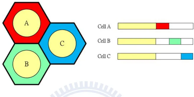
The major effect of cross-slot interference is caused by observed cell is transmit-ting uplink signal, but neighboring cell is executransmit-ting downlink transmission. This kind of cross-slot interference is called BS-to-BS cross-slot interference. On the other hand, the MS-to-MS cross-slot interference will be generated by observed cell is downlink and neighboring cell is uplink. However, the MS-to-MS cross-slot interference doesn’t degrade SINR seriously. Each cross-slot interference always causes in the cross time slot (CTS) region within a frame just likes Fig. 1.1. Cell A, cell B and cell C have different band-width requirements of uplink and downlink transmission. If each cell’s base station (BS) can adjust their uplink and downlink requirements, the CTS region will be generated in the intermediate zone within a frame. For uplink transmission, the strong BS-to-BS cross-slot interference will degrade SINR and may make received uplink signal can’t be demodulated. Hence, if system supports asymmetric traffics adaptively in each cell, system performance will be restrained due to this kinds of inter-cell interference. However, if we want to provide multimedia services with asymmetric services in next generation wireless communication systems, the problems of cross-slot interference must be solved or avoided.
Figure 1.1: Three cells (A,B,C) which support asymmetric traffic that causes cross-slot interference.
Recently, many researches want to overcome the cross-slot interference issues are briefly summarized as follows. [4] avoided strong cross-slot interference by employing antenna beamforming in each cell. In [5], the tri-sector cellular architecture was considered since taking shape of the virtual cells. Then, it fixed the same uplink over downlink time slot ratio (switching point) in time slot allocations to avoid the direct strong cross-slot interference from three adjacent sectors. Another approaches [6], [7], [8] considered the MS location information to make properly scheduling to avoid the MS locating at the cell boundary and transmitting in cross time slot region since this method can also increase the system performance, such as throughput and bit error rate (BER). There are more research just likes [9], [10], [11], [12], [13] also discuss the issues of cross-slot interference. We will investigate this kinds of literature about effect of cross-slot interference in Chapter 3.
There are many researches use time slot allocation strategy to avoid and reduce the effects of cross-slot interference. They always avoid the effects of cross-slot interference in time domain. Not many researches have investigated the effects of cross-slot interfer-ence issue in frequency domain. However, the future wireless system-OFDMA has more serious inter-cell interference. If system can support asymmetric traffics, the SINR will be degrade seriously due to the cross-slot interference. Hence, we want to solve this kind of problems by implementing FFR scheme in TDD-OFDMA system when supporting various asymmetric traffics in a multi-cellular system. We investigate the impact of cross-slot inter-ference in the FFR-based system, such as [14], [15], [16], [17], [18], [19]. FFR scheme is an approach which uses spectrums to exchange less inter-cell interference. The asymmet-ric traffic environments also have serious inter-cell interference than the symmetasymmet-ric traffic environment because of cross-slot interference. The FFR has two important factors which are inner region size and outer region reuse factor can be designed for improving system performance. System always use smaller frequency reuse factor in inner region that is near BS and larger frequency reuse factor in outer region that has longer distance between BS and MS. Hence, each cell can reuse more spectrums because the inner region is always
useing same frequency bands and maintains higher link quality for MS transmits signal at outer region due to avoid neighboring cell’s inter-cell interference. However, when MS transmit signal in the cross time slot region, system may reduce size of inner region or use larger outer region reuse factor to maintain higher link quality. Hence, we must design the appropriate FFR factors, such as inner region size, frequency reuse factor of each region and resource assignment to maximize spectrum efficiency with guaranteeing link reliability in different random asymmetric traffic environments.
1.3
Thesis Outline
The research in this thesis investigates the effects of inter-cell interference in a FFR based on TDD-OFDMA environment. We develop an analytical approach to evaluate the effects of inter-cell interference on the design of FFR factors. Furthermore, we provide some sim-ulation results to clarify advantages of using FFR in a multi-cellular system with supporting asymmetric services.
The remaining chapters of this work are organized as following. Chapter 2 reviews some background of 802.16m WiMAX standard. Chapter 3 discuss literature surveys about the effects of cross-slot interference, fractional frequency reuse and problem formulation. Chapter 4 analyzes the outage performance for FFR based on TDD-OFDMA systems with asymmetric traffics in a two-cell environment and investigates the size of cross time slot region to effect the system performance. Chapter 5 discusses advantages of FFR schemes in TDD-OFDMA multi-cellular environment. Chapter 6 provides some concluding remarks and suggestions for future research.
6
CHAPTER 2
Background of 802.16m WiMAX System
2.1
Orthogonal Frequency Division Multiple Access (OFDMA)
OFDMA is a multicarrier modulation technique that has found wide adoption in a widespread variety of high-data-rate communication systems, including WiMAX and LTE standard in fourth generation cellular system. Several advantages of OFDMA can improve transmis-sion performance, such as orthogonal frequency divitransmis-sion multiplexing (OFDM) modulation technique, frequency diversity and multi-user diversity...etd.
In wireless transmission environments, multi-path delay interference is a serious problem. The orthogonality of OFDM subcarriers may be lost when the signal passes through a time-dispersive radio channel due to inter-OFDM symbol interference. However, a cyclic extension of the OFDM signal can be performed to avoid this interference. Using the cyclic prefix (CP) method is getting the last part of the OFDM signal is added in the beginning of the OFDM signal. The addition of the CP makes the transmitted OFDM signal periodic and helps in avoiding inter-OFDM symbols.
In a frequency-selective channel, different modulations symbols can be transmit-ted by using OFDM technique which can be affectransmit-ted by different channel fading. We can consider the channel fading gain and group subchannels with higher channel gain to each mobile station (MS). Thus, OFDMA can achieve frequency diversity in variety channel fading environment. The OFDMA system will allocate subchannels to each MS due to
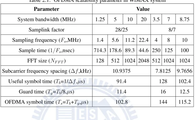
Table 2.1: OFDMA scalability parameter in WiMAX system
Parameter Value
System bandwidth (MHz) 1.25 5 10 20 3.5 7 8.75
Samplink factor 28/25 8/7
Sampling frequency (Fs,MHz) 1.4 5.6 11.2 22.4 4 8 10
Sample time (1/Fs,nsec) 714.3 178.6 89.3 44.6 250 125 100
FFT size (NF F T) 128 512 1024 2048 512 1024 1024
Subcarrier frequency spacing (Δf ,kHz) 10.9375 7.8125 9.7656
Useful symbol time (Tb=1/Δf ,µs) 91.4 128 102.4
Guard time (Tg=Tb/8,µs) 11.4 16 12.5
OFDMA symbol time (Ts=Tb+Tg,µs) 102.8 144 115.2
the available subcarriers may divided into several groups of subcarriers which are called subchannels. If we suitable arrange these subchannels, the multiuser diversity can improv-ing the transmission quality by different subcarrier and subchannel permutation. However, subchannels form the minimum frequency resource-unit allocated by base station for up-link and downup-link scheme. Therefore, different subchannels may be allocated to different users as a multiple-access mechanism in uplink and downlink.
2.1.1
OFDMA Scalable Parameter
The architecture is based on a scalable subchannelization structure with variable Fast Fourier Transform (FFT) sizes according to the system bandwidth. However, coherence time, Doppler shift and coherence bandwidth of the channel are considered in a scalable structure where the FFT sizes scale with bandwidth to keep the subcarrier spacing fixed. The Table 2.1.1 shows the scalability range proposed in IEEE 802.16m WiMAX standard.
2.1.2
Subchannelizaion of the OFDMA System
In an OFDMA system, subchannels may be constituted using either subcarriers pseudo-randomly distributed across the frequency spectrum or contiguous subcarriers. Subchan-nels are formed by using distributed subcarriers provide more frequency diversity, which is particularly useful for mobile applications. In WiMAX system, the pseudo-randomly dis-tributed scheme is called partial usage of full usage of subcarriers (FUSC) and subcarriers (PUSC).
The subchannelization scheme based on contiguous subcarriers in WiMAX stan-dard is called band adaptive modulation and coding (Band AMC). Although this scheme must lost frequency diversity, Band AMC allows system designers to exploit multiuser diversity that is allocating subchannels to users based on their frequency response or con-sidering the co-channel interference from neighboring cell. In general, multiuser diversity can provide significant gains in system capacity by different allocation scheme.
Full Usage Subcarrier (FUSC) and Partial Usage Subcarrier (PUSC)
In the downlink transmission, the data subcarriers can be used to create the various sub-channels by FUSC and PUSC permutation that are called DL-FUSC and DL-PUSC respec-tively. However, uplink case only support PUSC permutation method called UL-PUSC. They are formed subcarrier as a subchannel by each pseudorandom permutation approach. In the case of DL-FUSC, each subchannel is made up of 48 data subcarriers, which are dis-tributed evenly throughout the en tire frequency band. The DL-PUSC is similar to FUSC except that the subcarriers are first divided onto six groups. Permutation of subcarriers formed subchannels is performed independently within each group. Thus, each group can be separated from each others and still keep the frequency diversity. In the UL-PUSC the subcarriers are first divided into various tiles consist of four subcarriers over three OFDM symbols. The tiles are renumbered and using a pseudorandom numbering sequency, and
divided into six groups. Each subchannel is created using six tiles from a single group.
Band Adaptive Modulation and Coding (AMC)
According to use the Band AMC permutation mode, each subchannels is constituted by adjacent subcarriers. Although frequency diversity is lost, implement of multiuser diver-sity is easier. The system can adaptive allocate subchannels to each user with the highest SINR/capacity or choice subchannels with less co-channel interference since the multiuser diversity provides improvement in link reliability, system capacity and throughput. In the WiMAX system, we can use Band AMC permutation. Nine adjacent subcarriers and one pilot subcarrier are used to form a bin. A Band AMC subchannel consists of six contiguous bins. Thus, a Band AMC subchannel can consist of one bin over six consecutive symbols, two consecutive bins over three consecutive symbols, or three consecutive bins over two consecutive symbols. Hence, the size of subchannel is dependent on the subcarrier permu-tation mode. For instance, each subchannel is 8, 16, or 24 sybcarriers by six, three, or two OFDM symbols.
2.2
Frame Structure in the WiMAX System
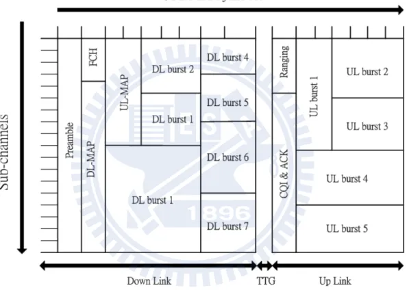
In the OFDMA system, base station (BS) can allocate different subchannels to arrival users for uplink and downlink within a frame duration. Fig. 2.1 illustrates one sample OFDMA frame structure for a time division duplex (TDD) implementation in WiMAX system. The frame is divided into downlink and uplink sub-frames separated by transmit/receive and re-ceive/transmit transition gaps (TTG and RTG) to prevent downlink and uplink transmission collisions. Each frame starts with a preamble followed by frame control header (FCH), the DL-MAP, and a UL-MAP, respectively. The preamble is used for synchronization and the FCH provides the frame configuration information such as MAP message, coding scheme, and usable subchannels...etd. However, system always uses the DL-MAP and UP-MAP to
allocate subchannels for different users need to implement uplink and downlink. The up-link Ranging contains the mobile station (MS) information such as power adjustment and bandwidth request. The uplink CQICH and ACK is allocated for the MS feedback channel state information and downlink HARQ acknowledge.
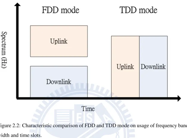
Both frequency division duplexing (FDD) and time division duplexing (TDD) are allowed in the WiMAX system. No matter the former or the latter have some advantages respectively forth to used in the frame of wireless transmission system. Fig. 2.2 shows characteristic of FDD and TDD mode on the spectrum usage over timing allocation.
2.2.1
Frequency Division Duplexing (FDD) Mode
In the case of FDD mode, the uplink and downlink subframes are transmitted simultane-ously in different carrier frequencies and the size of two subframes always are symmetric due to the type of traditional wireless transmission are almost voice and text message. Two kinds of data need symmetric traffic of uplink and downlink transmission since the FDD mode is easier to implement. Thus, the standard organization always assign two groups of spectrum to support uplink and downlink requirement respectively. However, the FDD always waste spectrum as paired spectrum for uplink and downlink in current transmis-sion requirement due to more applications need various uplink/downlink ratio, such as web browser, interactive game or real-time streaming. The spectrum can’t share to each other transmit mode. If MS needs more downlink transmission requirement, the uplink spectrum will waste for the idle transmission state. Nevertheless, the FDD mode need to transmit and receive signal simultaneously. Therefore, the transceiver is difficult to design and has a lot of cost. The fix size of FDD mode for uplink/downlink is not suitable used in the future.
Figure 2.2: Characteristic comparison of FDD and TDD mode on usage of frequency band-width and time slots.
2.2.2
Time Division Duplexing (TDD) Mode
Most WiMAX system operators force to deploy TDD mode to transmit uplink and down-link signal respectively as the flexible sharing of bandwidth. Comparison of TDD and FDD mode, TDD mode has more advantages as considering spectrum usage ratio and transceiver cost. The TDD mode uses the time to separate uplink and downlink within a frame duration. System can allocate spectrum dynamically on the instant and TDD mode has a reciprocal channel that can be exploited for spatial processing and has a simpler transceiver design. However, there are some disadvantages need to notice while using TDD mode such as the need for synchronization across multiple base station and existence of strong cross-slot interference that will affect system performance.
2.3
Frequency Reuse Scheme
A good interference management (IM) scheme that can mitigate inter-cell interference. Frequency reuse is a conventional approach to reduce the effects of the inter-cell interfer-ence. However, the generic frequency reuse approach faces the trade-off between spectral efficiency and inter-cell interference mitigation. The former is affected by reuse factor is small and the latter can be achieved by big reuse factor. Hence, the FFR scheme [20] is introduced in this chapter.
FFR is an approach to limit the inter-cell interference. How to use it to get the best performance is an interesting issue. For example, the IEEE 802.16m WiMAX supports frequency reuse factor of one which means that all cells operate at only one frequency band to maximize spectrum efficiency. Nevertheless, the strong inter-cell interference is a main issue. Traditional frequency reuse technique can improve the inter-cell interference, but it will lower spectrum utilization. The concept of FFR is based on the idea of applying a reuse factor of one in the zone near the BS, and a higher reuse factor in the zone near the cell boundary. The FFR technique can reduce the inter-cell interference from neighbor cells for the MS near cell boundary and take care of spectrum utilization.
2.3.1
Traditional Frequency Reuse Scheme
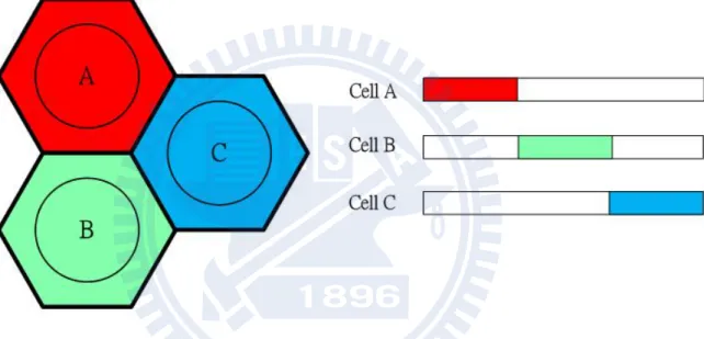
The simplest frequency reuse scheme is a frequency reuse factor-n system. About the tra-ditional frequency reuse scheme is shown as in Fig. 2.3. Total bandwidth can be used in the system will be divide into several partitions (n>1) and assign these partitions to neighboring cells that be shaped as a cluster. In a cluster, the neighboring cell will be assigned different bands to avoid inter-cell interference. For instance, Fig. 2.3 is tradi-tion frequency reuse scheme of n=3, there are not inter-cell interference in each cluster. And each cell will be surrounded by six immediate neighboring cells which use orthogo-nal bands and each bandwidth equal to one-third of the total bandwidth. The traditioorthogo-nal
Figure 2.3: The architecture of traditional frequency reuse scheme and demonstrates the scenario of spectrum usage ratio.
Figure 2.4: The architecture of fraction frequency reuse scheme by considering interference mitigation at outer region and outer region reuse factor equals to three.
frequency reuse scheme can trade the spectral efficiency for the benefits of completing can-cellation of stronger inter-cell interference from first-tier cells. As we know, the larger n will receive lower inter-cell interference at receiver, but also degrades spectral efficiency in each cells. Hence, use the tradition frequency reuse scheme in the cellular systems is not the best interference management scheme in the view of system performance.
2.3.2
Fractional Frequency Reuse (FFR) Scheme
The fractional frequency reuse scheme is used to increase spectrum efficiency and improve the link quality while MS locate at cell boundary. As Fig. 2.4 shown, each cell divide into two groups, the region of inner and outer. As we realize, if MS arrives to the inner region, they could have good link quality by less propagation lossy than MS locate at outer region. Hence, the MS locates at inner region can tolerate more effects of inter-cell interference from neighboring cells than outer region. On the other hand, the outer region
always has larger propagation lossy since if they also receive inter-cell interference from neighboring cells, signal transmission is almost outage that means the received signal can’t be demodulated. Therefore, FFR scheme is major solution to improve link quality when MS transmits signal at cell boundary and maintain spectrum efficiency. In the inner region always use frequency reuse factor equals to one or smaller than frequency reuse factor of outer region. However, the frequency reuse factor of outer region is always larger than one for improving the effects of inter-cell interference from neighboring cells. For example, there is a FFR scheme with frequency reuse factor is one at inner region and three at outer region in Fig. 2.4. The total bandwidth will classify four parts to assign in different region for a cluster is combined by cell A, B and C. First part is used in inner region and other parts are assigned to outer region of each cells. In a cluster, the inner region shares the same bandwidth to increase spectrum utilization in a cell and the outer region uses different bandwidth to avoid inter-cell interference.
For the FFR scheme, two important design parameters must be noticed are the size of inner region and the outer region reuse factor. The size of inner region is associated with maintaining spectrum efficiency. The outer region reuse factor will affect spectrum utilization and overall inter-cell interference. Two parameters will affect the system per-formance in FFR scheme. Hence, system must design this two factors to improve system performance in difference systems.
17
CHAPTER 3
Effect of Cross-Slot Interference in FFR based
TDD-OFDMA Multi-Cellular System
Multimedia services are popularly used in the third generation communication systems. In the future, there are more various applications with different uplink/downlink bandwidth requirements. However, the traditional bandwidth requirements of uplink and downlink transmission are always symmetric by voice and messages. No matter using TDD or FDD mode, system always allocates symmetric traffics in each cell. Thus, inter-cell interference always comes from neighboring cells at different entities between transmitter and receiver. This kinds of inter-cell interference is called non cross-slot interference, such as BS-to-MS and BS-to-MS-to-BS interference. Oppositely, the inter-cell interference is coming from same entities between transmitter and receiver called cross-slot interference, such as BS-to-BS and MS-to-MS cross-slot interference which doesn’t cause in FDD and TDD with fix uplink/downlink ratio among all cells.
Furthermore, more various applications with different uplink/downlink bandwidth requirements are generated. Each cell may support different kinds of uplink/downlink ratio dynamically. Thus, the dynamic TDD mode is popularly researched in the recent years. The key advantage of the dynamic TDD mode is its capability of flexibly adjusting up-link and downup-link bandwidth by allocating different numbers of time slot. However, the cross-slot interference may be generated in dynamic TDD mode and it becomes the largest resistance of supporting dynamic TDD mode, because will degrade SINR seriously. If
we want to support multimedia service in next generation system, the effects of cross-slot interference must be solved or reduced for guaranteeing link quality.
3.1
Literature Survey
There are several researches to overcome the issue of cross-slot interference on dynamic TDD mode in the recent years. They are briefly introduced as follows.:
3.1.1
Effect of Cross-Slot Interference in Different Wireless System
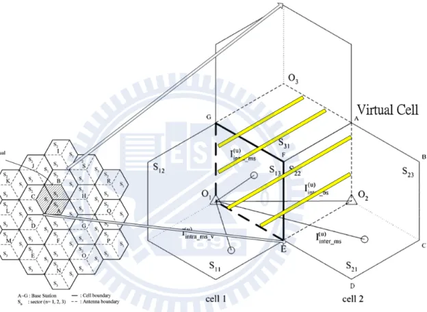
Interference Analysis and Resource Allocation for TDD-CDMA Systems to Support Asymmetric Services by Using Directional Antennas [5]
This paper explores the advantages of using directional antennas in TDD-CDMA system to support asymmetric traffic services and analyze the interference of the TDD-CDMA sys-tem with trisector cellular architecture, where three directional antennas are employed at each base station. The system architecture is shown in Fig.3.1. Each directional anten-nas can support different uplink and downlink ratios for the sector coverage to implement asymmetric traffic services, but the strong cross-slot interference is frequently generated.
A sample approach to avoid this interference is fixing same uplink and downlink ratio among all cells. The disadvantage of this sample approach is loss the flexibility of assigning uplink and downlink ratio as increasing new call blocking rate in the cell. Thus, the concept of virtual cell is introduced in the paper and virtual cell is composed of three sectors from the three adjacent cells. They can provide an additional degree of freedom for allocating radio resource. Fixing the same uplink and downlink ratio by considering requirement of the virtual cell to avoid the cross-slot interference. This approach can lower the new call blocking likes a dynamic TDD mode and improves the distribution of SINR better than other traditional approaches.
Figure 3.1: The architecture of virtual cell is composed of three sectors from the three adjacent cells.
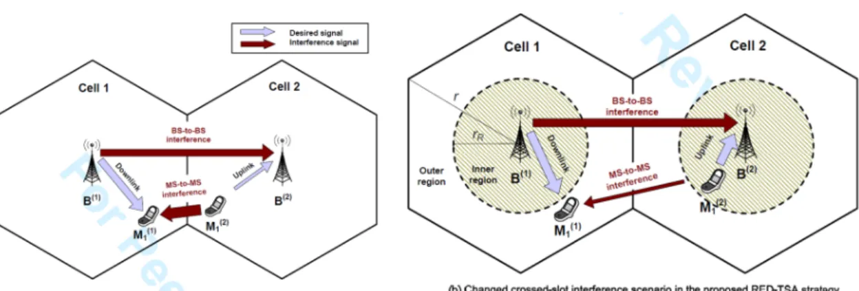
Figure 3.2: The architecture of Red-TSA considers the MS location information to schedule time slots.
Time Slot Allocation Based on Region and Time Partitioning for Dynamic TDD-OFDM Systems [8]
In this paper, the MS location information is being considered to make properly schedul-ing to avoid the MS is locatschedul-ing at the cell boundary and transmittschedul-ing in cross time slot region in a TDMA system. The author provide a new time slot allocation (TSA) strategy, region-based decentralized time slot allocation (RED-TSA) strategy which utilizes partial location information of MS. The diagram of RED-TSA is shown in Fig. 3.2 and it can effective to reduce the effects of cross-slot interference than traditional strategies, Fix-TSA and Greedy-TSA. The Fix-TSA which fixes the same ratio of uplink and downlink time slots in all cells to mitigate the cross-slot interference and the Greedy-TSA is just like dynamic TDD mode which each cell can support different uplink and downlink ratios.
The new RED-TSA is a new scheduling approach to reduce the effect of cross-slot interference. Each cell is divided into inner and outer region. According to consider the effect of path loss, the inner region has better link quality than outer region. If Ms transmits or receives signal at inner region will get higher SINR than MS locates at outer region. Hence, the MS locates at inner region can tolerate stronger inter-cell interference
and due to this reason which the RED-TSA arranges thesis MS that locates at inner region transmit or receives signal on time slots which near the predefined boundary (likes the switch point introduced in last section). This scheduling method can reduce the effects of cross-slot interference as avoiding received the cross-slot interference when Ms locates at cell boundary.
Furthermore, the author also provides an analytical approach to find out the optimal predefined boundary and analyze system performance by using the Central Limit Theo-rem and Queueing TheoTheo-rem. The mathematical analysis can quickly compute the system performance and find out the optimal predefined boundary.
3.1.2
Inter-Cell Interference Reduction of Fractional Frequency Reuse
(FFR) Multi-Cellular System
Optimal Fractional Frequency Reuse (FFR) in Multi cellular OFDMA System [14] The fractional frequency reuse technique is a good interference management that intro-duced in last chapter. However, the advantages of fractional frequency reuse is introintro-duced in this paper. In addition, the author proposes an optimal analysis (Primal Dual Interior Point Method) [21] to find out the optimal design factors in FFR scheme based OFDMA system in downlink case. This analysis method will compute the optimal numbers of sub-channel can be used in each region. The simulation result shows the advantages on FFR scheme that can against the effects of inter-cell interference and improves system through-put by suitable design factors of FFR scheme. Hence, the fractional frequency reuse scheme is suitable to solve the effects of inter-cell interference.
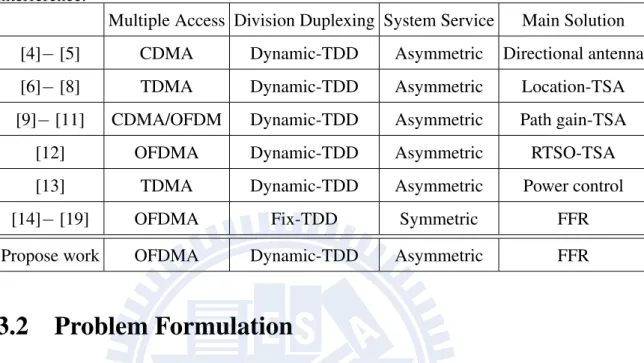
Table 3.1: Comparison between propose work and recent research about effect of cross-slot interference.
Multiple Access Division Duplexing System Service Main Solution
[4]− [5] CDMA Dynamic-TDD Asymmetric Directional antenna [6]− [8] TDMA Dynamic-TDD Asymmetric Location-TSA [9]− [11] CDMA/OFDM Dynamic-TDD Asymmetric Path gain-TSA
[12] OFDMA Dynamic-TDD Asymmetric RTSO-TSA
[13] TDMA Dynamic-TDD Asymmetric Power control
[14]− [19] OFDMA Fix-TDD Symmetric FFR
Propose work OFDMA Dynamic-TDD Asymmetric FFR
3.2
Problem Formulation
Comparison of thesis research about the effects of inter-cell interference including cross-slot interference. We can find out the effects of cross-cross-slot interference is stronger than general inter-cell interference (non cross-slot interference) especially BS-to-BS cross-slot interference. If asymmetric traffic services want to be implemented in the future, we must reduce or avoid the effects of cross-slot interference in TDD-OFDMA system. Hence, we propose FFR-based TDD-OFDMA system that can effectively reduce the problems of cross-slot interference by dynamically design the factors of FFR scheme at any instanta-neous asymmetric traffic requirements among multi-cellular environments. Comparison table is shown in Table. 3.1. Furthermore, performance analysis and simulation result will be introduced in next chapter.
23
CHAPTER 4
Outage Performance Analysis for Fractional
Frequency Reused TDD-OFDMA Systems with
Asymmetric Traffics: Two Cell Case
In this chapter, we present an analytical approach to design the inner region size for the fractional frequency reused (FFR) time division duplex (TDD) orthogonal frequency divi-sion multiple access (OFDMA) systems when supporting asymmetrical traffic services. In TDD systems, supporting asymmetrical traffics can be achieved by adjusting the ratio of downlink and uplink transmission period. Nevertheless, the inter-cell interference may be deteriorated by the cross-slot interference resulting from the different downlink and uplink ratios among neighboring cells. Although the FFR scheme can overcome the inter-cell in-terference, impact of the cross-slot interference of TDD systems due to various downlink to uplink traffic ratios in different cells on the inner region size of a FFR-based OFDMA system is an open issue to our best knowledge. Intuitively, the larger the inner region of a FFR system, the higher system capacity will be achieved. Thus, we can provide a sys-tematic method to determine the size of the inner region of FFR-based OFDMA system for different ratios of the downlink to uplink traffic among two neighbor cells.
4.1
System Mode
4.1.1
Two Cellular Scenario
We consider a TDD-OFDMA system with FFR scheme and supports asymmetric services in a two-cell environment just likes Fig. 4.1. Note that the ratios of the downlink traffic to the uplink traffic are different in the two cells. Thus, the strong cross-slot interference occur and can degrade received SINR seriously. Hence, it is crucial to resolve the heavy cross-slot interference issue when employing FFR in the TDD-OFDMA system.
The important design parameters for FFR based TDD-OFDMA system are the in-ner region radius and the outer region reuse factor. The inin-ner region radius is associated with the numbers of subchannel can be used in each zone. The outer region reuse factor will affect spectrum utilization and the overall inter-cell interference. We will vary the in-ner radius and outer radius in our analysis to find out the maximum inin-ner radius that can guarantee the success probability in the asymmetric traffic environments.
4.1.2
Resource Assignment Approach
The fairness approach to allocate the numbers of subchannel is proportional to numbers of user in each region. In the TDD frame structure likes Fig. 4.2 which is divided into into two groups according to its uplink/downlink requirements. If we randomly assign resource units to the arriving MS, it will increase the probability of generating cross-slot interference. We must assign resources to MS regularly. The uplink slot assignment begins from the head slot of a frame until the switching point, and downlink slot assignment begins from the end slot of a frame to the switching point. In this way called regular assignment, cross-slot interference can be avoided when cell traffic is low.
4.1.3
Cross Time Slot (CTS) Region of Asymmetric Services
In an asymmetric service systems like Fig. 4.1, each cell has their own downlink/uplink
requirements (ΔDL:ΔU L) and will result in the CTS region. In this region, we analyze
the effects of cross-slot interference that degrades SINR in the TDD-OFDMA system. Let
ΔDL
1 be the downlink requirements in cell 1 and ΔDL2 the downlink requirements in cell 2.
We define the CTS region as ΔDL2 -ΔDL1 [9]. The positive value of CTS represents cell 2
has more downlink slots than cell 1. Oppositely, the negative value of CTS means cell 2 has more uplink slots than cell 1. Hence, if the CTS is equal to zero, the cell 1 and cell 2 has same downlink and uplink time slots requirement.
4.2
Performance Metrics
4.2.1
Radio Propagation Effects
We consider the following channel effects: path loss, shadowing fading, and multi-path delay fading to analyze success probability for the FFR based TDD-OFDMA two-cells cellular system.
Path Loss
The pathloss decays with the propagation distance r between the transmitter and the re-ceiver is modelled as a common empirical formula approximation [22] that is formulated as following: PLoss(r) = P0 ( d0 r )α , (4.1)
where α is the pathloss exponent factor and the value of measured pathloss P0is considered
by reference distance of d0. However, P0is often approximated as (4πλ)2 when d0 = 1. λ is
Shadowing Fading
Shadowing fading can be modelled as a log-normal random variable 1010ξ in the 802.16m
WiMAX system [1]. The variable ξ is distributed as Gaussian random variable with zero mean. Different propagation path will affect levels of the standard deviation because of the different antenna height. In this thesis, the standard deviation on BS-to-BS path is 3 dB and 10 dB on other propagation paths, such as BS-to-MS, MS-to-BS and MS-to-MS link.
Multi-Path Delay Fading
Some buildings locate around the propagation path that will reflect waves which may be received at the receiver. Each of these reflected signals have different paths, amplitude and phases. The Rayleigh distribution [23] is used in this chapter to characterize the multi-path delay fading for analysis success probability on FFR based TDD-OFDMA system. On each subcarrier k, we can formulate the multi-path delay fading h as a Rayleigh distributed random variable with the probability density function (pdf) as following:
fh(h) = 2he−h
2
. (4.2)
Let Y = h2, the cumulative density function (cdf) of Y can be written as
FY(y) = 1− e−y . (4.3)
4.2.2
Signal to Interference-and-Noise Ratio (SINR)
According to consider effects of path loss, shadowing fading and multi-path delay fading,
we can calculate the total received signal power Pri,j,k at the receiver on k-th subcarrier for
the j-th subchannel of transmitter is located in cell i by the following formulation,
Pri,j,k = Pt(Ci,j,k) PLoss(ri,j,k) 10 ξi,j,k
where Pt(Ci,j,k) is the transmission power on k-th subcarrier for the j-th subchannel of
transmitter is located in cell i. Ci,j,k may be [U, D, X] represents that transmission modes
on k-th subcarrier for the j-th subchannel of cell i. U , D and X are uplink transmission, downlink transmission and the k-th subcarrier isn’t used to transmit signal, respectively.
The shadowing fading 10ξi,j,k10 is a log-normal random variable with ξi,j,k is a Gaussian
random variable and the multi-path delay fading is labelled as hi,j,k that represents the
channel fading on k-th subcarrier for the j-th subchannel of transmitter is located in cell i. In a multi-cellular system with I cells, the observed receiver may received co-channel interference comes from other cells. Hence, the total interference on the k-th subchannel can be formulated as,
I
∑
i=2
Pt(Ci,j,k) PLoss(ri,j,k) 10
ξi,j,k
10 (h
i,j,k)
2
(4.5) Then, the SINR on k-th subcarrier for the j-th subchannel of transmitter is located in cell 1 can be written as
SIN R1,j,k = Pt(C1,j,k) PLoss(r1,j,k) 10 ξ1,j,k 10 (h1,j,k)2 I ∑ i=2
Pt(Ci,j,k) PLoss(ri,j,k) 10
ξi,j,k
10 (hi,j,k)2+ N0Wsub
(4.6)
where N0 is the noise power density and Wsubis bandwidth size of a subcarrier.
4.2.3
Success Probability of Wireless Transmission
In OFDMA systems, the minimum transmission unit is a subchannel that is grouped by several subcarriers. The lowest level of effective SINR can be demodulated at the receiver
is rth = 0 that doesn’t consider error coding scheme [24]. The success probability of
wireless transmission is the probability that effective SIN Ri,j is higher than the threshold
rthjust likes following formulation:
ps = Pr(SIN Ri,j > rth) , (4.7)
4.3
Total Success Probability of Wireless Transmission for
the FFR based TDD-OFDMA System
According to the total probability theorem, we can calculate the total success probability for the FFR based TDD-OFDMA system by the following formulation,
ps=Ain· [ Pr(C1 = U )· pIs(C1 = U ) + Pr(C1 = D)· pIs(C1 = D) ] + Aout· [ Pr(C1 = U )· pNs (C1 = U ) + Pr(C1 = D)· pNs (C1 = D) ] , (4.8)
where Ain presents the probability that MSs arrive to the cell 1 and locate at the inner
region. Oppositely, Aout is the probability that MSs arrive to the outer region in the cell
1. Pr(C1 = U ) and Pr(C1 = D) are the ratio of uplink and downlink requirement. The
success probability in the inner region of the cell 1 transmission mode is given can be represented as pIs(C1 = U ) =Pr(C2 = X|C1 = U ) pIs(C1 = U, C2 = X) + Pr(C2 = U|C1 = U ) pIs(C1 = U, C2 = U ) + Pr(C2 = D|C1 = U ) pIs(C1 = U, C2 = D) , (4.9) pIs(C1 = D) =Pr(C2 = X|C1 = D) pIs(C1 = D, C2 = X) + Pr(C2 = U|C1 = D) pIs(C1 = D, C2 = U ) + Pr(C2 = D|C1 = D) pIs(C1 = D, C2 = D) , (4.10)
In the inner region of the cell 1, receivers may receive inter-cell interference that come from neighboring cells because of frequency reuse scheme. Hence, there are three kinds of success probability may be generated in the inner region. First, the receiver doesn’t
receive inter-cell interference just like pIs(C1 = U, C2 = X) and pIs(C1 = D, C2 = X),
because neighboring cells doesn’t use same resource units (subchannel). Second, receivers
may be suffered the effects of non cross-slot interference, pIs(C1 = U, C2 = U ) and
pI
s(C1 = D, C2 = D). In the second situation, the neighboring cells have same
transmis-sion mode. The third kind of success probability is the receiver receives strong cross-slot interference that is generated when neighboring cells have different transmission mode. We will calculate each kinds of success probability in the next section.
4.4
Success Probability in the Flat-Fading Channel
4.4.1
Effective Subchannel Gain in the Flat-Fading Channel
In the flat-fading environment, each subcarriers of a subchannel always have same
multi-path delay fading that is hi,j,1 = hi,j,2 = ... = hi,j,Msub, where Msub is the number of
subcarriers are grouped as a subchannel. Hence, we can formulate received power Pri,j for
the j-th subchannel as following:
Pri,j =
M∑sub
k=1
Pri,j,k
= Pt(Ci,j)PLoss(ri,j)10
ξi,j 10 ( 1 Msub M∑sub k=1 (hi,j,k)2 )
= Pt(Ci,j)PLoss(ri,j)10
ξi,j 10 ( 1 Msub M∑sub k=1 yi,j,k )
= Pt(Ci,j)PLoss(ri,j)10
ξi,j
10 yi,j , (4.11)
where yi,j = yi,j,k and yi,jis the effective subchannel gain which is distributed as an
fY (y) = e−y , (4.12)
FY (y) = 1− e−y . (4.13)
However, the effective SIN R1,j on the j-th subchannel of transmitter is located in
cell 1 under a flat-fading channel can be represented as
SIN R1,j = Pt(C1,j) PLoss(r1,j) 10 ξ1,j 10 y1,j I ∑ i=2
Pt(Ci,j) PLoss(ri,j) 10
ξi,j
10 yi,j + N0Wc
, (4.14)
where the bandwidth of a subchannel Wc = MsubWsub.
4.4.2
Success Probability without Inter-Cell Interference in the
Flat-Fading Channel
The success probability without inter-cell interference under conditions of y1,j,r1,j, ξ1,j are
given can be defined as following:
pNs (C1,j|y1,j, r1,j, ξ1,j) = Pr{SNR1,j > rth} = Pr { Pt(C1,j)PLoss(r1,j)10 ξ1,j 10 y1,j N0Wc > rth } = Pr { y1,j > rth N0Wc Pt(C1,j)PLoss(r1,j)10 ξ1,j 10 } = 1− FY [ rth N0Wc Pt(C1,j)PLoss(r1,j)10 ξ1,j 10 ] , (4.15)
where rthis the required received-SINR threshold which is chosen in accordance with the
selected modulation and coding scheme [24].
For considering the propagation distance r1,jand shadowing effects ξ1,j, the success
probability without inter-cell interference can be evaluated as:
pNs (C1,j) = ∫∫ pNs (C1,j|y1,j, r1,j, ξ1,j)· fR1,j(r1,j)fξ(ξ1,j)dr1,jdξ1,j = ∫∫ { 1− FY [ rth N0Wc Pt(C1,j)PLoss(r1,j)10 ξ1,j 10 ]} · fR1,j(r1,j)fξ(ξ1,j)dr1,jdξ1,j = ∫ ∞ −∞ ∫∫ S1 e−rth N0Wc Pt(C1,j )PLoss(r1,j )10 ξ1,j 10 · e− (ξ1,j)2 2σ2 √ 2πσ dx1,jdy1,jdξ1,j , (4.16)
where S1 is the set of coordination in the cell 1 and fξ(ξ1, j) = e
−(ξ1,j)
2 2σ2
√
2πσ represents the
distribution of the log-normal shadowing.
4.4.3
Success Probability with Inter-Cell Interference in the Flat-Fading
Channel
The success probability subjects to the inter-cell interference for the jth subchannel in cell
1 under conditions of y1,j,r1,j,ξ1,j,y2,j,r2,j and ξ2,j are given can be defined as follows:
pIs(C1,j, C2,j|y1,j, r1,j, ξ1,j, y2,j, r2,j, ξ2,j) = Pr{SINR1,j > rth} = Pr { Pt(C1,j)PLoss(r1,j)· 10 ξ1,j 10 y1,j Pt(C2,j)PLoss(r2,j)· 10 ξ2,j 10 y2,j + N0Wc > rth }
= Pr { y1,j > rth ( Pt(C2,j) Pt(C1,j) ) ( PLoss(r2,j) PLoss(r1,j) ) 10ξ2,j −ξ1,j10 y2,j + rth N0Wc Pt(C1,j)PLoss(r1,j)· 10 ξ1,j 10 } = Pr{y1,j > γjy2,j+ βj} = 1− FY [γjy2,j+ βj] , (4.17) where γj = rth ( Pt(C2,j) Pt(C1,j) ) ( PLoss(r2,j) PLoss(r1,j) ) 10ξ2,j −ξ1,j10 , (4.18) βj = rth N0Wc Pt(C1,j)PLoss(r1,j)· 10 ξ1,j 10 , (4.19)
Then, r2,j and ξ2,j are the propagation distance and shadowing effects between
transmitter at cell 2 and receiver at cell 1 for the jth subchannel. γj is the ratio of received
interference power over received signal power and βj is the ratio of thermal noise power
over received signal power. However, the equation (4.17) can be integrated by considering
effects of channel fading y2,j,
pIs(C1,j, C2,j|r1,j, ξ1,j, r2,j, ξ2,j) = ∫ ∞ 0 pIs(C1,j, C2,j|y1,j, r1,j, ξ1,j, y2,j, r2,j, ξ2,j)· fY (y2,j) dy2,j = ∫ ∞ 0 {1 − FY [γjy2,j + βj]} · e−y2,jdy2,j = ∫ ∞ 0 e−(γjy2,j+βj)· e−y2,jdy 2,j = ∫ ∞ 0 e−(1+γj)y2,j · e−βjdy 2,j = e −βj 1 + γj , (4.20)
Considering the propagation distance r2,j and shadowing effects ξ2,j, we can
calcu-late the success probability under the propagation distance r1,j and shadowing effects ξ1,j
are given as pIs(C1,j, C2,j|r1,j, ξ1,j) = ∫ ∞ 0 ∫ R2 pIs(C1,j, C2,j|r1,j, ξ1,j, r2,j, ξ2,j) fR2,j(r2,j) fξ(ξ2,j) dr2,jdξ2,j , (4.21)
where R2is the set of the distance between transmitter at cell 2 and receiver at cell 1 for the
j-th subchannel. Then, we can obtain the success probability with inter-cell interference as
following: pIs(C1,j, C2,j) = ∫ ∞ 0 ∫ R1 pIs(C1,j, C2,j|r1,j, ξ1,j) fR1,j (r1,j) fξ(ξ1,j) dr1,jdξ1,j , (4.22)
where R1 is the set of the distance between transmitter and receiver at cell 1 for the jth
subchannel.
4.5
Success Probability in the Frequency-Selective Fading
Channel
4.5.1
Effective Subchannel Gain in the Frequency-Selective Fading
Channel
In the frequency-selective fading environment, each subcarriers of a subchannel always
have different multi-path delay fading that is hi,j,1 6= hi,j,2 6= ... 6= hi,j,Msub, where Msubis
the number of subcarriers are grouped as a subchannel. Hence, we can formulate received
Pri,j =
M∑sub
k=1
Pri,j,k
= Pt(Ci,j)PLoss(ri,j)10
ξi,j 10 ( 1 Msub M∑sub k=1 (hi,j,k)2 ) = ( 1 Msub Pt(Ci,j) ) PLoss(ri,j)10 ξi,j 10 (M sub ∑ k=1 zi,j,k )
= Pt(Ci,j,k)PLoss(ri,j)10
ξi,j
10 zi,j , (4.23)
where Pt(Ci,j) = Msub· Pt(Ci,j,k). The zi,j is the effective subchannel gain which is the
summation of Msubsub-carriers gain and distributes as an Erlangian random variable with
the pdf and cdf as following:
fZ(z) = zM−1e−z (M − 1)! , (4.24) FZ(z) = 1− M∑−1 t=0 zte−z t! . (4.25)
However, the effective SIN R1,j on the j-th subchannel of transmitter is located in
cell 1 under a frequency-selective fading channel can be represented as
SIN R1,j = Pt(C1,j) PLoss(r1,j) 10 ξ1,j 10 z1,j I ∑ i=2
Pt(Ci,j) PLoss(ri,j) 10
ξi,j
10 zi,j + N0Wc
, (4.26)
4.5.2
Success Probability without Inter-Cell Interference in a
Frequency-Selective Fading Channel
The success probability without inter-cell interference under conditions of z1,j,r1,j, ξ1,j are
pNs (C1,j|z1,j, r1,j, ξ1,j) = Pr{SNR1,j > rth} = Pr { Pt(C1,j)PLoss(r1,j)10 ξ1,j 10 z1,j N0Wc > rth } = Pr { z1,j > rth N0Wc Pt(C1,j)PLoss(r1,j)10 ξ1,j 10 } = Pr{z1,j > βj} = 1− FZ[βj] . (4.27)
For considering the propagation distance r1,jand shadowing effects ξ1,j, the success
probability without inter-cell interference can be evaluated as:
pNs (C1,j) = ∫∫ pNs (C1,j|z1,j, r1,j, ξ1,j)· fR1,j(r1,j)fξ(ξ1,j)dr1,jdξ1,j = ∫∫ {1 − FZ[βj]} · fR1,j(r1,j)fξ(ξ1,j)dr1,jdξ1,j = ∫ ∞ −∞ ∫∫ S1 [M−1 ∑ t=0 (βj) t e−βj t! ] ·e− (ξ1,j)2 2σ2 √ 2πσ dx1,jdy1,jdξ1,j , (4.28)
4.5.3
Success Probability with Inter-Cell Interference in the
Frequency-Selective Fading Channel
The success probability subjects to the inter-cell interference for the j-th subchannel in cell