A Compact 35-65 GHz Up-Conversion Mixer with Integrated
Broadband Transformers in 0.18-
ȝm SiGe BiCMOS Technology
Ping-Chen Huang, Ren-Chieh Liu, Jeng-Han Tsai, Hong-Yeh Chang, Huei Wang,
John Yeh
†, Chwan-Ying Lee
†, and John Chern
†Department of Electrical Engineering and Graduate Institute of Communication Engineering,
National Taiwan University, Taipei, 106, Taiwan, R. O. C.
†
Taiwan Semiconductor Manufacturing Company, Hsinchu, 300, Taiwan, R. O. C.
Abstract — This paper presents a compact 35-65 GHzGilbert cell up-convert mixer implemented in TSMC 0.18-ȝm SiGe BiCMOS technology. Integrated broadband transformers and meandered thin-film microstrip lines were utilized to achieve a miniature chip area of 0.6 mm × 0.45 mm. The compact MMIC has a flat measured conversion loss of 7 ± 1.5 dB and LO suppression of more than 40 dB at the RF port from 35 to 65 GHz. The power consumption is 14 mW from a 4-V supply. This is a fully integrated millimeter-wave active mixer that has the smallest chip area ever reported, and also the highest operation frequency among up-conversion mixers using silicon-based technology.
Index Terms — HBT, millimeter-wave (MMW), mixer, SiGe, transformer, up-converter.
I. INTRODUCTION
Millimeter-wave (MMW) communication systems have been attracting attention because of the wider bandwidth and higher data rate that can meet the ever-increasing need in the multimedia age. In these systems, compact, low-cost, and low-power equipment is required. MMW up-conversion mixer is one of the key components in the transmitter. Since the use of direct up-conversion and down-conversion techniques is a promising approach for their potential for low-power monolithic operation and extremely broad bandwidth [1], up-conversion mixers with balanced topology are essential to suppress the LO to RF leakage. Although balanced resistive mixers can achieve wide bandwidth and consume zero dc power, they usually suffer from the large chip area required for the quarter-wavelength matching stubs and baluns [2]-[5], making them more difficult to be integrated in a low-cost, compact system. MMW up-conversion mixers using the sub-harmonic pumped (SHP) principle were also reported. However, higher LO power is required and the additional passive baluns also increase chip size [6]-[7].
In this paper, a compact up-conversion mixer that converts 1-GHz signal to 35-65 GHz is presented. The mixer utilizes a Gilbert cell multiplier, which no
quarter-wavelength matching stubs are required and hence compact circuit layout is achieved. Also it is integrated with broadband transformers that have been developed for millimeter-wave applications [8] and meandered thin-film microstrip lines in the matching circuits to reduce the chip size. The chip size is 0.6 mm × 0.45 mm.
With broadband matching at the LO and RF ports, the MMIC achieve a flat conversion loss frequency response of 7 ± 1.5 dB and LO suppression of more than 40 dB at the RF port from 35 GHz to 65 GHz under power consumption of 14 mW from a 4-V supply. A comparison between recently reported MMW up-conversion mixers and this work is given in Table I. To the authors’ knowledge, this is the fully integrated millimeter-wave active mixer with the smallest chip area ever reported, and also the highest operation frequency among up-conversion mixers using silicon-based technology.
II. TECHNOLOGY DESCRIPTION
The mixer was fabricated in TSMC 0.18-ȝm mixed-signal SiGe BiCMOS technology featuring a metal stack with 1 poly layer and 6 metal layers. The thickness of the top metal is 3.5 ȝm for the realization of the inductive transmission lines. The substrate conductivity is about 10ʳ ȍ-cm. In this process, the HBT has an fT of 120 GHz and
and an fmax of 130 GHz with a 1.5-V supply. The MIM
capacitors are developed using oxide inter-metal dielectric, with capacitance of 1 fF/mm2.
III. CIRCUIT DESIGN
Figure 1 shows the circuit schematic of the MMW up-converter. The up-converter consists of the Gilbert cell core and two compact Machand-type transformers with broadband characteristics at the LO and RF ports. The transformer is a Machand balun with each coil as a quadrature coupler [8]. However, unlike the conventional
design of Machand-type transformers, the linewidths and line gaps of this transformer are adapted to the design rule limit of 2.6 ȝm to minimize the chip area. Therefore, this transformer operates in the higher frequency and occupies a miniature chip area. By using metal 5 and 6 for low loss interconnection, the transformer achieves a broadband bandwidth with 6.5 ± 0.5 dB insertion loss from 20 to 70 GHz. The simulated return and insertion losses of the transformer are shown in Fig. 2.
The matching circuits for the LO and RF ports are designed to match the output impedance of the transformers. All the inductors in this mixer were implemented with thin-film microstrip lines. Since the signal (Metal 6) to ground (Metal 1) path is on the top of a 6 ȝm height oxide, it can be laid out compactly and meanderingly to minimize the chip size. The minimum line width, given by the maximum tolerable current density, has been selected for the upper metallization layer
in order to minimize the line length. In this process, the thin-film microstrip line of 50-ȍ characteristic impedance is about 15 ȝm. The line width of matching inductors are selected to be 3 ȝm wide (Z0= 100 ȍ) for physical length
and quality factor. The emitter size of the Gilbert cell up-converter was determined so that the mixer achieves broadband matching performance while maintaining the required conversion loss. The emitter size of the HBT is 0.2 ȝmʳ × 4.52 ȝm. The devices of the gain stage were biased at 1 mA and 1.5 V at the peak gm. The base voltage
for the devices of the switching stage is biased through resistors, but that for the devices of the gain stage is biased through the off-chip IF rat-race. The fabricated Gilbert cell up-converter is shown in Fig. 3, with a chip area of 0.7 mm × 0.45 mm.
RF
Balun
LO
Balun
V
IFV
IFV
LOV
RFLO Match
RF Match
0 10 20 30 40 50 60 70 -20 -15 -10 -5 0 M a gnit ude [ d B] Frequency [GHz] Insertion Loss Return LossFig. 2. Simulated return and insertion losses of the Machand-type
transformer. Fig. 3. Micrograph of the Gilbert cell up-converter. (0.7 mm × 0.45 mm)
IV. MEASUREMENTRESULTS
The IF input signal of the up-converter is fed through an off-chip hybrid rat-race hybrid. The center frequency of the rat-race hybrid is designed at 1-GHz with 3-dB bandwidth of 300 MHz. The measured conversion gain versus LO power of the Gilbert cell up-convert mixer in different LO frequencies is presented in Fig. 4. With LO input power, IF input power, and IF input frequency of 5 dBm, -20 dBm, and 1 GHz, respectively, the simulated and measured conversion losses are shown in Fig. 5. The measured conversion losses of upper- and lower-sideband signals are 7 ± 1.5 dB from 35 GHz to 65 GHz. An LO suppression of more than 40 dB is achieved over this frequency range. The discrepancy between the simulation
and measurement may be due to the uncertainty of the models in millimeter-wave range.
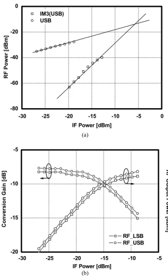
The measured conversion gain swept with LO pumped power is saturated at -7 dBm, where the LO and IF input power are 5 dBm and -20 dBm, respectively. The output third-order intermodulation intercept point (OIP3) and output 1-dB compression point (OP1dB) is -16 and -25
dBm at 40 GHz, respectively, as shown in Fig. 6(a) and (b). The collector bias is 4 V while the base bias is optimized to be 3 and 2 V for the switching stage and the gain stage, respectively. The total dc power consumption is 14 mW. Table I summarizes the recently reported MMW conversion mixers. This Gilbert cell MMW up-converter demonstrated the most compact chip area and the highest operation frequency among up-conversion mixers using silicon-based technology.
20 30 40 50 60 70 -50 -40 -30 -20 -10 0 20 30 40 50 60 70 -50 -40 -30 -20 -10 0 [dB] LO Frequency [GHz] Conversion Gain (LSB) Conversion Gain (USB) LO Suppression
Simulated Conversion Gain
Fig. 5. Simulated and measured conversion gain and LO suppression of the Gilbert cell up-convert mixer with LO power, IF power, and IF frequency of 5 dBm, -20 dBm, and 1 GHz, respectively.
-10 -5 0 5 10 15 -25 -20 -15 -10 -5 0 Co n ver s io n G a in [ d B ] LO Power [dBm] fLO = 30 GHz fLO = 40 GHz fLO = 50 GHz fLO = 59 GHz -10 -5 0 5 10 15 -25 -20 -15 -10 -5 0 Co n ver s io n G a in [ d B ] LO Power [dBm] fLO = 30 GHz fLO = 40 GHz fLO = 50 GHz fLO = 59 GHz
Fig. 4. Measured conversion gain versus LO power of the Gilbert cell up-convert mixer with IF power, and IF frequency of -20 dBm, and 1 GHz, respectively. -30 -25 -20 -15 -10 -5 0 -80 -60 -40 -20 0 RF P o we r [d Bm] IF Power [dBm] IM3(USB) USB (a) -30 -25 -20 -15 -10 -5 -20 -15 -10 -5 R F Out put P o w e r [d Bm ] Co nve rsion Gain [d B] IF Power [dBm] RF_LSB RF_USB (b)
Fig. 6. Measured (a) third-order intermodulation intercept point (b) 1-dB compression point of the Gilbert cell up-convert mixer with LO frequency, LO power, IF frequency of 40 GHz, 5 dBm, and 1 GHz ̈́ 100 kHz, respectively.
V. CONCLUSION
A compact Gilbert cell up-conversion mixer in 0.18-ȝm SiGe BiCMOS technology is presented in this paper. The mixer consists of broadband and compact Machand-type transformers and meandered thin-film microstrip lines to reduce the chip size. From 35 GHz to 65 GHz, the MMIC achieves a flat conversion loss with less than 3 dB variation. With the total chip area of 0.28 mm2, which is the most compact MMW up-converter ever reported, it can be easily integrated into single-chip transmitters.
ACKNOWLEDGEMENT
This work is supported by NTU-TSMC Joint-Development Project and National Science Council of Taiwan, R. O. C. (Project no. NSC 93-2752-E-002-002-PAE, NSC 93-2219-E-002-024, and NSC 93-2213-E-002-033). The authors would like to thank Chun-Hsien Lien for the chip testing and the Chip Implementation Center for providing design software.
REFERENCES
[1] B. Razavi, “Challenges and trends in RF design,” Proc. 9th Annu.IEEE Int. ASIC Conf. and Exhibit, pp. 81–86, 1996,.
[2] S. Gunnarsson, K. Yhland, H. Zirath, “pHEMT and mHEMT ultra wideband millimeterwave balanced resistive mixers,” IEEE MTT-S Int. Microwave Symp. Dig., vol. 2, pp. 1141-1144, Jun. 2004.
[3] Y. Mimino, K. Nakamura, Y. Hasegawa, Y. Aoki, S. Kuroda, and T. Tokumitsu, “A 60 GHz millimeter-wave MMIC chipset for broadband wireless access system front-end,” IEEE MTT-S Int. Microwave Symp. Dig., vol. 3, pp. 1721-1724, Jun. 2002.
[4] K. Nishikawa, K. Kamogawa, T. Nakagawa, B. Piernas, and K. Arakki, “Broadband and compact SiBJT balanced up-converter MMIC using Si 3-D MMIC technology,” IEEE MTT-S Int. Microwave Symp. Dig., vol. 1, pp. 87-90, May. 2001.
[5] J. P. Torres, F. Fortes, M. Joao Rosario, J. M. Dieudonne, J. Costa Freire, “Monolithic mixers with MESFETs technology to up and down convert between C and V band,” IEEE Microwave and Millimeter-Wave Monolithic Circuits Symp. Dig., pp. 167-170, May
1995.
[6] K. Hettak, G. A. Morin, and M. G. Stubbs, “A novel miniature multilayer MMIC CPW single sideband CPW mixer for up conversion at 44.5 GHz,” IEEE Microwave and Wireless Components Letters, vol. 15, no. 9, pp. 606-608, Sep. 2005.
[7] H. Hayashi, H. Okazaki, A. Kanda, T. Hirota, and M. Muraguchi, “Millimeter-wave-band amplifier and mixer MMIC’s using a broad-band 45° power divider/combiner,” IEEE Trans. Microwave Theory and Tech., vol. 46, no. 6, pp. 811-819, Jun. 1998.
[8] P.-S. Wu, H.-Y. Chang, M.-D. Tsai, T.-W. Huang, and H. Wang, “New miniature 15-20 GHz continuous phase/amplitude control MMICs using 0.18-um CMOS technology,” to appear in IEEE Trans. Microwave Theory and Tech., Jan. 2006.
[9] A. Orzati, F. Robin, H. Meier, H. Benedikter, W. Bächtold, “A V-band up-converting InP HEMT active mixer with low LO-power requirements,” IEEE Microwave and Wireless Components Letters,
vol. 13, no. 6, pp.202-204, Jun. 2003. TABLE I
COMPARISON OF RECENTLY REPORTED MMW UP-CONVERSION MIXERS
Ref. Technology Type Topology Bandwidth
(GHz) Conversion Gain (dB) PLO (dBm) LO Isolation (dB) Power Consumpti on (mW) Die Size (mm2)
[3] 0.15ȝm InGaP/InGaAs pHEMT Passive Single-balanced
gate mixer 50-70 -14 ± 1 0 > 15 N/A 1.67 × 1.34
[5] GaAs MESFET Passive Antiparallel
diode pair 62-66 -9 ± 1 7 >9.8 N/A N/A
[9] 0.2ȝm InP pHEMT
fT=135 GHz, fmax = 200 GHz
Active Single-transistor 64.5 1 -1.7 > 30 N/A 3.7 × 1.4
[2] 0.14ȝm pHEMT
fT=95 GHz, fmax = 180 GHz
Passive Double-balanced
resistive mixer 30-50 -6 ~ -12 1.5 > 30 N/A 2 × 1.5
[6] 0.18ȝm pHEMT Passive/SHP Antiparallel
diode pair 43-46 -10 12 8-20 N/A 1.7 × 1.7
[4] 0.25ȝm 3-D Si BJT Active Base active mixer 12-27 2.5 ± 2.5 0 30 9.8 1.4 × 0.7
[7] 0.3ȝm GaAs MESFET Passive/SHP Antiparallel
diode pair 21.6 -30.8 -12.9 ± 1.1 8 > 50 N/A 1.8 × 1.3
This work f 0.18ȝm SiGe BiCMOS
T=120 GHz, fmax = 130 GHz
Active
Gilbert cell with integrated passive
broadband balun