行政院國家科學委員會專題研究計畫 成果報告
氧化錫奈米線成長及其電化學觸媒支撐材應用研究(第 2 年)
研究成果報告(完整版)
計 畫 類 別 : 個別型
計 畫 編 號 : NSC 98-2221-E-011-028-MY2
執 行 期 間 : 99 年 08 月 01 日至 100 年 07 月 31 日 執 行 單 位 : 國立臺灣科技大學化學工程系
計 畫 主 持 人 : 蔡大翔
計畫參與人員: 碩士班研究生-兼任助理人員:Leonardy A 碩士班研究生-兼任助理人員:梁嘉文 碩士班研究生-兼任助理人員:楊禮榮 碩士班研究生-兼任助理人員:葉俐君 碩士班研究生-兼任助理人員:陳俊宏 碩士班研究生-兼任助理人員:趙余亘 碩士班研究生-兼任助理人員:姚志杰 碩士班研究生-兼任助理人員:羅仁捷 碩士班研究生-兼任助理人員:李怡親
報 告 附 件 : 出席國際會議研究心得報告及發表論文
公 開 資 訊 : 本計畫可公開查詢
中 華 民 國 100 年 11 月 17 日
中 文 摘 要 : 此研究計畫有兩個研究主題,製備及量測以氧化錫奈米線支 撐鉑錫觸媒的結構化陽極 Pt/Sn/SnO2NW/CP,它的結構與活 性;另一主題,分析及控制氧化錫奈米線成長的晶癖。 氫還 原後的鉑錫觸媒分析包括循環伏安法量測甲醇乙醇氧化電 流,一氧化碳剝除實驗,及定電壓長時電流量測,對照結構 分析以瞭解氫還原對活性的影響。結果顯示,氧化錫奈米線 的還原程度對活性極為重要,尤其是零價的金屬錫,能對抗 一氧化碳毒化作用,製備多個不同還原程度的
Pt/Sn/SnO2NW/CP 陽極之中,以 0.1 mg cm-2 Pt, 從沉積 0.4 mg cm-2 SnO2NW 奈米線還 54%,即為 0.17 mg cm-2 Sn,這個陽極有最佳的抗一氧化碳毒化表現,也是活性最高 的觸媒,它的一氧化碳氧化電流始於 0.08 V (vs.
Ag/AgCl)。與市售 Johnson-Matthey HiSPEC5000 PtRu/C 觸 媒相比較,我們的結構化陽極在氧化甲醇方面活性稍遜,但 在氧化乙醇方面則催化活性遠高於 HiSPEC5000。
用氧化鋁單晶藍寶石 Sapphire (SA) (100) 、(110) 兩種 基材,分析奈米金輔助成長,說明單晶的晶格能控制氧化錫 奈米線成長行為。SA(100) 表面的氧化錫晶體優選的匹配晶 面,是(001),成長方向 rutile[101],晶體成長的氧化錫晶 體被相互垂直的{010} { 01}所包圍形成長方形外形的奈米 線;SA(110) 表面氧化錫晶體成長稍有不同,沿伸方向 rutile[100],晶體(101)是優選的匹配晶面,此基材生長的 氧化錫晶體被相互垂直的{010}, {001}所包圍形成長方形外 形。 兩晶面上成長,除了包圍的晶面相異之外,主要是在水 平方向的匹配圖案不同,SA(100) 表面奈米線有兩個垂直方 向可傾斜,表面四重對稱形成排線方格,SA(110) 表面上有 三個方向可以傾斜,所以形成像魚骨一樣的圖案。此外,我 們也證實,可用拉曼光譜的 A1g 譜線變寬現象反推求得平均 線徑。
中文關鍵詞: 鉑錫電化學觸媒、奈米線支撐、一氧化碳剝除、乙醇氧化催 化活性、氧化錫成長晶癖、成長晶面、成長方向、拉曼光 譜、spatial correlation model。
英 文 摘 要 : Electrochemical activities and structural features of Pt/Sn catalysts supported by hydrogen- reduced SnO2 nanowires (SnO2NW) are studied. The SnO2NW supports have been grown on a carbon paper which is
commercially available for gas diffusion purposes.
Partial reduction of SnO2NW raises the CO tolerance of the Pt/Sn catalyst considerably. The zero-valence
tin plays a significant role in lowering the oxidation potential of COads. For a carbon paper electrode loaded with 0.1 mg cm-2 Pt and 0.4 mg cm-2 SnO2NW, a conversion of 54% SnO2NW into Sn metal (0.17 mg cm-2) initiates the COads oxidation reaction at 0.08 V, shifts the peak position by 0.21 V,
maximizes the CO tolerance. The presence of Sn metal enhances the activities of both methanol and ethanol oxidation, with a more pronounced effect on the oxidation current of ethanol whose optimal value is analogous to those of PtSn/C catalysts reported in literature. In comparison with a commercial PtRu/C catalyst, the optimal Pt/Sn/SnO2NW/CP exhibits a somewhat inferior activity toward methanol, and a superior activity toward ethanol oxidation.
Tilted SnO2 nanowires (SnO2NW) have been grown and aligned on the sapphire (SA) substrate of orientation (100) or (110). Their structural and spectroscopic features are studied using scanning electron
microscopy, transmission electron microscopy, X-ray diffraction, and Raman spectroscopy, with the
emphasis on the wire roots. On the SA(100) substrate, the (001) facet of SnO2 preferentially matches the SA(100) plane. The longitudinal SnO2 crystal grows in the [101] direction with the enclosing facets of {010} and {10 }, which are perpendicular to form its rectangular cross-section. On the SA(110) substrate, the (101) facet of SnO2 matches the SA(110) plane, and the wire crystal elongates in the [100] direction with the enclosing orthogonal facets {010} and {001}.
Since the angle between two SnO2 facets (101) and (001) is 34 , the SnO2NWs on SA(100) and (110) are tilted with an angle of 56 from the substrate normal to the growth direction. The main difference between two SnO2NWs is the planar alignment, which creates a rectangular grid pattern on SA(100) and a herringbone pattern on SA(110). We further
demonstrate the wire size, evaluated via fitting the line profile of Raman A1g mode, can be controlled in the range of 30 – 80 nm through manipulating the sputtered thickness of gold layer on both substrates.
英文關鍵詞: PtSn electrocatalyst; nanowires support; CO stripping; activity on catalyzing ethanol
oxidation; SnO2 growth habit; enclosing crystal plane; growth direction; Raman spectroscopy;
spatial correlation model.
1
行政院國家科學委員會補助專題研究計畫 ▓成果報告
□期中進度報告
氧化錫奈米線成長及其電化學觸媒支撐材應用研究
計畫類別:▓個別型計畫 □整合型計畫 計畫編號:NSC 98-2221-E-011-028-MY2
執行期間: 2009 年 8 月 1 日至 2011 年 7 月 31 日 執行機構及系所:台灣科技大學化工系
計畫主持人:蔡大翔 (Dah-Shyang Tsai) 共同主持人:
計畫參與人員:Leonardy Adrianus 、梁嘉文 、張混傑、洪文鍾、蔡佳珊、趙 余亘。
成果報告類型(依經費核定清單規定繳交):□精簡報告 ▓完整報告
本計畫除繳交成果報告外,另須繳交以下出國心得報告:
□赴國外出差或研習心得報告
□赴大陸地區出差或研習心得報告
▓出席國際學術會議心得報告
□國際合作研究計畫國外研究報告
處理方式:除列管計畫及下列情形者外,得立即公開查詢
□涉及專利或其他智慧財產權,□一年□二年後可公開查詢 中 華 民 國 年 月 日
2
目 錄
摘要 3
ABSTRACT 4
一、計畫源起及目地 5
1.1 氧化錫奈米線承載之鉑錫觸媒 5
1.2 氧化錫奈米線成長控制 6
二、結果與討論 6
2.1 氧化錫奈米線成長控制研究 6
2.2 氧化錫奈米線作電化學觸媒支撐研究 14
三、成果報告自評表 20
四、出席國際會議報告 22 發表之期刊論文
1. Wen-Zhong Hung, Wen-Hung Chung, Dah-Shyang Tsai, David P. Wilkinson, Ying-Sheng Huang, (2010) “CO tolerance and catalytic activity of Pt/Sn/SnO2 nanowires loaded on a carbon paper”, Electrochimica Acta, 55, 2116-2122.
2. Adrianas Leonardy, Wen-Zhong Hung, Dah-Shyang Tsai, Chen-Chia Chou, Ying-Sheng Huang, (2009) “Structural features of SnO2 nanowires and Raman spectroscopy analysis”, Crystal Growth & Design, 9, 3958-3963.
3. Shun-Ping Chiao, Dah-Shyang Tsai, David P. Wilkinson, Yi-Ming Chen, Ying-Sheng Huang (2010)“Carbon supported Ru1-xFexSey electrocatalysts of pyrite structure for oxygen reduction reaction”, International J. Hydrogen Energy, 35, 6508-6517.
4. Xie-Hong Jian, Dah-Shyang Tsai, Wen-Hung Chung, Ying-Sheng Huang, Feng-Jiin Liu (2009) “Pt–Ru and Pt–Mo electrodeposited onto Ir–IrO2 nanorods and their catalytic activities in methanol and ethanol oxidation”, J. Mater.
Chem., 19, 1601-1607.
5. Tsu-Yung Jin, Dah-Shyang Tsai, Wen-Hung Chung, Feng-Jiin Liu, (2008) “Electrochemical Behavior of
Gel-Derived Lanthanum Calcium Cobalt Ferrite Cathode in Contact with LAMOX Electrolyte”, J. Am. Ceram. Soc.
91 [7] 2217-2222.
6. Wen-Hung Chung, Dah-Shyang Tsai, Yi-Ming Chen, Ying-Sheng Huang, Chen-Chia Chou, Chin-hsin J. Liu (2008)
“Thermally decomposed (110) surface of RuO2 single crystal”, Solid State Comm., 146, 462-467.
附件 – HFC2011 會議論文
3
氧化錫奈米線成長及其電化學觸媒支撐材應用研究
摘 要
此研究計畫有兩個研究主題,製備及量測以氧化錫奈米線支撐鉑錫觸媒的結構化陽極 Pt/Sn/SnO2NW/CP,它的結構與活性;另一主題,分析及控制氧化錫奈米線成長的晶癖。 氫 還原後的鉑錫觸媒分析包括循環伏安法量測甲醇乙醇氧化電流,一氧化碳剝除實驗,及定電壓 長時電流量測,對照結構分析以瞭解氫還原對活性的影響。結果顯示,氧化錫奈米線的還原程 度對活性極為重要,尤其是零價的金屬錫,能對抗一氧化碳毒化作用,製備多個不同還原程度 的 Pt/Sn/SnO2NW/CP 陽極之中,以 0.1 mg cm-2 Pt, 從沉積 0.4 mg cm-2 SnO2NW 奈米線還 54%,
即為 0.17 mg cm-2 Sn,這個陽極有最佳的抗一氧化碳毒化表現,也是活性最高的觸媒,它的一 氧化碳氧化電流始於 0.08 V (vs. Ag/AgCl)。與市售 Johnson-Matthey HiSPEC5000 PtRu/C 觸媒 相比較,我們的結構化陽極在氧化甲醇方面活性稍遜,但在氧化乙醇方面則催化活性遠高於 HiSPEC5000。
用氧化鋁單晶藍寶石 Sapphire (SA) (100) 、(110) 兩種基材,分析奈米金輔助成長,說明 單晶的晶格能控制氧化錫奈米線成長行為。SA(100) 表面的氧化錫晶體優選的匹配晶面,是 (001),成長方向 rutile[101],晶體成長的氧化錫晶體被相互垂直的{010} {101}所包圍形成長方 形外形的奈米線;SA(110) 表面氧化錫晶體成長稍有不同,沿伸方向 rutile[100],晶體(101)是 優選的匹配晶面,此基材生長的氧化錫晶體被相互垂直的{010}, {001}所包圍形成長方形外形。
兩晶面上成長,除了包圍的晶面相異之外,主要是在水平方向的匹配圖案不同,SA(100) 表面 奈米線有兩個垂直方向可傾斜,表面四重對稱形成排線方格,SA(110) 表面上有三個方向可以
傾斜,所以形成像魚骨一樣的圖案。此外,我們也證實,可用拉曼光譜的 A1g譜線變寬現象反
推求得平均線徑。
關鍵詞:鉑錫電化學觸媒、奈米線支撐、一氧化碳剝除、乙醇氧化催化活性、氧化錫成長晶癖、
成長晶面、成長方向、拉曼光譜、spatial correlation model。
4
ABSTRACT
Electrochemical activities and structural features of Pt/Sn catalysts supported by hydrogen- reduced SnO2 nanowires (SnO2NW) are studied, using cyclic voltammetry, CO stripping voltammetry, scanning electron microscopy, and X-ray diffraction analysis. The SnO2NW supports have been grown on a carbon paper which is commercially available for gas diffusion purposes.
Partial reduction of SnO2NW raises the CO tolerance of the Pt/Sn catalyst considerably. The zero-valence tin plays a significant role in lowering the oxidation potential of COads. For a carbon paper electrode loaded with 0.1 mg cm-2 Pt and 0.4 mg cm-2 SnO2NW, a conversion of 54%
SnO2NW into Sn metal (0.17 mg cm-2) initiates the COads oxidation reaction at 0.08 V (vs. Ag/AgCl), shifts the peak position by 0.21 V, and maximizes the CO tolerance. Further reduction damages the support structure, reduces the surface area, and deteriorates the catalytic activity. The presence of Sn metal enhances the activities of both methanol and ethanol oxidation, with a more pronounced effect on the oxidation current of ethanol whose optimal value is analogous to those of PtSn/C catalysts reported in literature. In comparison with a commercial PtRu/C catalyst, the optimal Pt/Sn/SnO2NW/CP exhibits a somewhat inferior activity toward methanol, and a superior activity toward ethanol oxidation.
Tilted SnO2 nanowires (SnO2NW) have been grown and aligned on the sapphire (SA) substrate of orientation (100) or (110). Their structural and spectroscopic features are studied using scanning electron microscopy, transmission electron microscopy, X-ray diffraction, and Raman spectroscopy, with the emphasis on the wire roots. On the SA(100) substrate, the (001) facet of SnO2 preferentially matches the SA(100) plane. The longitudinal SnO2 crystal grows in the [101] direction with the enclosing facets of {010} and {101}, which are perpendicular to form its rectangular cross-section.
On the SA(110) substrate, the (101) facet of SnO2 matches the SA(110) plane, and the wire crystal elongates in the [100] direction with the enclosing orthogonal facets {010} and {001}. Since the angle between two SnO2 facets (101) and (001) is 34, the SnO2NWs on SA(100) and (110) are tilted with an angle of 56 from the substrate normal to the growth direction. The main difference
between two SnO2NWs is the planar alignment, which creates a rectangular grid pattern on SA(100) and a herringbone pattern on SA(110). We further demonstrate the wire size, evaluated via fitting the line profile of Raman A1g mode, can be controlled in the range of 30 – 80 nm through manipulating the sputtered thickness of gold layer on both substrates.
Keywords: PtSn electrocatalyst; nanowires support; CO stripping; activity on catalyzing ethanol oxidation; SnO2 growth habit; enclosing crystal plane; growth direction; Raman spectroscopy;
spatial correlation model.
5
一、計畫源起及目地
進行國家型計畫氧化釕氧化銥奈米桿的合成與應用過程,已觸及利用這類一維材料作為觸 媒的支撐材,甚至提供輔助性的催化活性構想,最接近的例子,利用部份還原的氧化銥奈米桿 作為輔助白金觸媒的支撐材,幫助解決甲醇氧化時產生毒化問題,而且因為一維材料的孔道直 接,方便離子擴散,這類觸媒材料,之後被稱作奈米結構化觸媒(nanostructured catalysts),我 們的 PtIr-IrO2NT 是早期少數的論文之一,Chi-Chi Shan, Dah-Shyang Tsai, Ying-Sheng Huang, Sie-Hong Jian, Chia-Liang Cheng, (2007) “Pt-Ir-IrO2NT Thin-wall Electrocatalysts Derived from IrO2 Nanotubes and Their Catalytic Activities in Methanol Oxidation”, Chem. Mater., 19 (3) 424-431.
1.1 氧化錫奈米線承載之鉑錫觸媒
因為目前高密度氫氣儲存的問題仍沒有簡易的解決之道,若能直接使用液態甲醇(CH3OH,
MeOH) 或乙醇(C2H5OH, EtOH)作為燃料,則能大幅簡化燃料儲存問題,進而簡化整體儲存及 燃料電池能源裝置,金屬錫與白金的合金是已知氧化乙醇的活性最高觸媒之一,計劃構想利用 通常在燃料電池的氣體擴散層(Gas diffusion layer, GDL)的碳紙(carbon paper, 以下簡稱 CP)為 載體,於載體表面上成長氧化錫奈米線,將其表面還原成錫金屬,利用碳紙的導電性與氧化錫 奈米線的立體結構的好處,製作成多重結構陽極電極,再電鍍白金金屬觸媒搭配還原後錫金屬,
成為 Pt/Sn/SnO2 NWs/CP。
鉑觸媒是已知活性最高的觸媒,它能提供充份的氧化甲醇乙醇活性(意即大電流),低溫操 作下在窄小空間內能否提供充份的反應速率,決定這類電池能在眾多選擇中脫穎而出的必要條 件,但因為所有碳氫化合物進行電化學氧化反應時,都產生一氧化碳副產物,一氧化碳的碳原 子與 Pt 表面共價鍵牢固,難脫附,造成毒化現象。 最常見的辦法是尋找第二金屬,在 Pt 表 面鄰近位置產生氫氧基,氧化吸附的一氧化碳,重生鉑表面活性位置,令其活性維繫不墬。釕 金屬及錫金屬是兩個最有效在低電面表面吸附水,產生氫氧基的金屬。
觸媒表面PtRu及PtSn其催化甲醇的反應吸附機構如下【1,2】:
Pt-Ru:
3Pt + CH3OH → Pt3COH + 3H+ + 3e- (1-1) Ru + H2O → RuOH + H+ + e- (1-2) RuOH → RuO + H+ + e- (1-3) RuO + Pt3COH → Ru + 3Pt + CO2 + H+ + e- (1-4)
Pt-Sn:
Sn-Pt + CH3OH → Sn-Pt-CHO + 3H+ + 3e- (1-5) Sn-Pt-CHO+H2O → HO-Sn-Pt-CHO + H+ + e- (1-6) HO-Sn-Pt-CHO → HO-Sn-Pt-CO + H+ + e- (1-7) HO-Sn-Pt-CO → Sn-Pt + CO2 + H+ + e- (1-8)
6
釕及錫的作用,低電位提供氫氧基 OH,氧化吸附於鉑活性位置的 CO,此作用稱作雙金屬效 應(bifunctional effect),目前最常使用的抗毒化辦法。
1.2 氧化錫奈米線成長控制
低溫 PEM 燃料電池的核心是 Membrane Electrode Assembly (MEA),包括擴散層(diffusion layer)、觸媒層(catalyst layer)、高分子電解質薄膜(polymer electrolyte membrane),其中氣體擴 散層的碳紙目地,在於讓氣體均勻擴散通過 MEA,台灣碳能公司已有能力生產品質不錯的碳 紙,我們將在其中一面,靠近 Nafion 電解質的一面生長氧化錫奈米線。
研究工作中很重要的一部份,瞭解氧化錫奈米線的生長機構,此一研究工作不只與碳紙上 碳纖維表面相關也與氧化錫氣體感知器研究相關,氧化錫是已知最重要的一氧化碳氣體偵測器 (gas sensor),氧化錫奈米線可用於作氣體偵測材料,因為其晶面可以控制成長,不同晶面的感 測能力相異,瞭解怎樣的基材成長甚麼氧化錫晶面,對控制感測能力相當重要。
SnO2 奈米線化學氣相沉積之成長機構研究,第一步先瞭解,一維奈米線的成長方向,及
圍繞奈米線晶體的晶面及其單晶基材之間的關係,第二步分析及控制奈米線晶體的線徑,我們 用 Raman 光譜的譜線寬度反推得到線徑,由此我們知道線徑是由濺鍍的金膜厚度控制,金膜 dewetting 所得粒徑與膜厚密切相關,粒徑控制奈米線線徑,因此膜厚控制線徑。
氧化錫奈米線(SnO2NW)的陣列報導極少,因為它長得很快,當線長超過某定值時,奈米
線下垂糾纏在一起,將觀察不到整齊的陣列,前人研究都忽略它的排列問題及細部成長晶面,
我們研究用 Sapphire (SA) (100) 、(110) 基材證明雖是奈米金輔助成長,單晶的晶格能控制成 長行為。SA(100) 表面的氧化錫晶體成長方向 rutile[101],晶體(001)是優選的匹配晶面,成長 的氧化錫晶體被相互垂直的{010} {101}所包圍形成長方形外形的奈米線;SA(110) 表面氧化 錫晶體成長稍有不同,沿伸方向 rutile[100],晶體(101)是優選的匹配晶面,氧化錫晶體被相互 垂直的{010}, {001}所包圍形成長方形外形。 兩個 SA 單晶面上成長,除了包圍的晶面相異之 外,主要是在水平方向的匹配圖案不同,SA(100) 表面奈米線有兩個垂直方向可傾斜,表面四 重對稱形成排線方格,SA(110) 表面上有三個方向可以傾斜,所以形成像魚骨一樣的圖案。
二、結果與討論
2.1 氧化錫奈米線成長控制研究
選擇單晶表面作為基材,因為唯有晶格層級的有序排列,方能控制奈米線的成長,研究之 初,最大疑問在於,奈米金作為奈米線的成核點,是否抹去氧化錫及單晶表面晶格的匹配條件?
如果答案是肯定的,則我們無法控制奈米線的成長,幸好,答案是奈米金成核點不影響奈米線 與基材晶格匹配,因此,其匹配關係得用於控制成長。
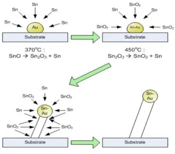
我們選擇水平管反應器,將氧化亞錫(SnO)置於上游,揮發的氧化亞錫蒸氣被帶到下游基 材,基材預鍍金膜,經過 dewetting 步驟,就是在 4002 C 停留五分鐘,讓金膜分別凝集成微 小顆粒,作為奈米線成長的成核點,錫蒸氣進入奈米金顆粒,飽和後再析出,成長氧化錫奈米 線,如 Figure 1 所示。此一圖解機構,也是一般認知的氧化錫奈米線成長模型。
Figure 2 比較 SA(100)及 SA(110)基材上的奈米線,陣列的方式顯然不同,SA(100) 基材
7
上呈現方格式排列,SA(110)基材上呈現魚骨排列。 其次注意到奈米線前端的金有時並不顯著,
內插圖所顯示的,有時只是一小片而已。意謂著只要 dewetting 成小片單獨的金顆粒,就能行 成生長點;不一定得是球形顆粒。
Figure 1 氧化錫奈米線的成長示意圖。dewetted 的奈米金吸收錫蒸氣,過飽合後,析出成奈米 線,因此頭上頂著金顆粒點。
Figure 2 Top views of SnO2NW grown on (a) SA(100) and (b) SA(110) substrates. Growth of nanowires was conducted at 645 C for 40 min on the substrates being sputtered Au for 20 s. Two SEM insets show the rectangular cross-sections of wire are slightly different on the two substrates.
Two TEM insets show the wire size is nearly the same with its gold droplet on top
8
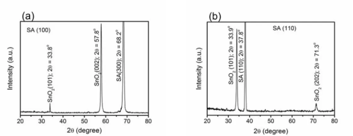
Figure 3 XRD patterns of SnO2NW grown on (a) SA(100) and (b) SA(110) at 645 C for 20 min.
The Au sputtering time was 20 s.
不同奈米線陣列的方式強烈暗示,這些奈米線依循某種磊晶方式成長,因為每一支奈米線 都是長方形截面,顯然它是個單晶,而且我們可用電鏡分析證明此點,所以問題回到根本,氧 化錫晶體在成長初期以何種晶面在氧化鋁單晶表面匹配?
Figure 3 的 X 光圖譜樣品,只經過短暫的成長時間,如此不會長太高,氧化錫晶體長太長 就看不出來它的成長癖好,因為長的晶體在 X 光下將呈現各種晶面,失去成長癖好特徵,Figure 3 所示 SA(100)表面癖好是金紅石(001),雖然有兩個繞射峰(101) (002),(002)強度遠高於(101),
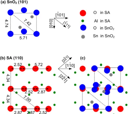
SA(110)表面癖好是金紅石(101),兩個繞射峰屬於相同家族(101)(202),將 SA(100)及金紅石(001) 晶格原子排起來堆疊,可瞭解晶格長度確實匹配之處,而且暗示我們氧化錫晶體的長方形格子 排列與此有關,Figure 4 的晶格匹配說明,氧化錫晶體可能向 SA[001]或 SA[010]方向排,因為 這兩個可選擇的基材方向相互垂直,所以我們掃描電鏡圖 Figure 2(a)呈現方格式圖案。
Figure 4 A schematic diagram of the lattice relation between SnO2(001) and SA(100). The surface
9
lattice is drawn for (a) SnO2(001), (b) SA(100), (c) SnO2(001) on top of SA(100).
Figure 5 所呈現的 SA(110)表面晶格匹配金紅石(101)的選擇有三個方向,分別是 SA[2 2 1], [110], [2 2 1],我們注意到這三個方向不互相垂直,所以氧化錫奈米線在表面上的排列並不是 方形,而是呈現三種方向交疊的魚骨排列,Figure 2(a)。
Figure 5 A schematic diagram of the lattice relation between SnO2(101) and SA (110). The surface lattice is drawn for (a) SnO2(101), (b) SA(110), (c) SnO2(101) on top of SA(110).
其次需要回答的問題是包住這些氧化錫奈米線的金紅石晶面是甚麼?雖然電鏡已說明這 些晶面是相互垂直,所以圍成長方形,但並未能提供晶面資訊,顯然這得將氧化錫奈米線括下 來,置於穿透式電鏡下,用電子繞射、高解析電鏡分析瞭解,Figure 6 提供在 SA(100)表面成 長之氧化錫奈米線的兩個垂直晶面,穿透式電鏡分析,Figure6(a)(b) 是高解析電鏡沿 zone axis [010]方向觀察的影像,(b) 是(a)的放大圖,容許精確量到晶格間距,較小的插圖是電子繞射圖 案,藉以判斷 zone axis 方向,Figure6(c)(d) 是 zone axis[101]的高解析電鏡圖,由此兩個繞射 結果,我們確定包裹奈米線的金紅石晶面{010} facet 及{101} facet,再利用 trace analysis 我們 找到奈米線的金紅石成長方向[101]。
同樣分析手法用於 SA(101)晶面成長之氧化錫奈米線,Figure 7(a)(b)的高解析電鏡沿 zone axis [001]觀察所得,Figure 7(c)(d)的 zone axis [010],所以確認裹奈米線的金紅石晶面{001}
facet 及{010} facet,trace analysis 得知奈米線的金紅石成長方向[100]。將上面結果綜合起來,
繪成 Figure 8 的示意圖,圖中包含所有 TEM 所獲至的晶面及成長方向資料,Figure 8 同時用根 部與基材形成角度驗證前面分析的正確性,兩種成長方向都是 34。
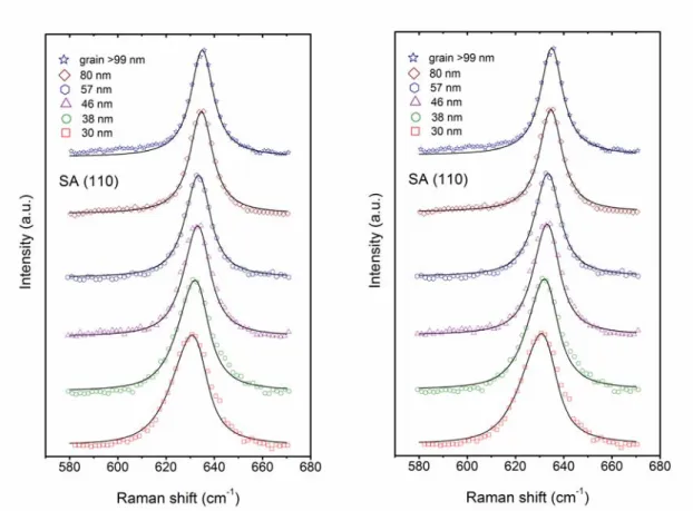
晶面關係之外,氧化錫奈米線徑也是重要資訊,我們發展 Raman 光譜分析的技術,用譜 線寬度分析可以得到平均線徑,Figure 9, 10 所示為 Raman 光譜最強的譜線 A1g mode 隨線徑縮
10
小而變寬的現象,分析依據 spatial correlation model (SC model),物理源由,起因於 first-order Raman scattering 的強度(intensity),隨著晶格振動範圍受到線徑限縮(confinement),造成聲子波 向量的不確定性,從而使峰線變寬及移動,因為奈米線是一維材料,限縮的尺寸是線徑,所以 可以用下面的 correlation function,關聯強度 I() at frequency 及線徑 L1,
2 2
3 2
) 2 / ( ) (
) , 0 ) (
( q
q
d qC
I (1)
(q) : the phonon dispersion curve being a function of the wave vector q,
: the natural line width,
C(0,q) : the Fourier coefficient of the phonon confinement function
2 2 2 2 2
2 2 2 2 2
1 2 1 2
2
1 )
32 ( 1 ) 16 / exp(
) 16 / exp(
) , , 0
( q q q L q L erf iqL
C L1 : the wire diameter,
L2 : the wire length.
對 SnO2NW 而言,L1 << L2 ,簡化成下式,
2 2
3 2
2 1 2
) 2 / ( ) ) (
exp( 16 )
(
q
q d L
I q
(2)
其中(q)2 A{A2B[1cos(q)]}1/2
A 及 B 根據將氧化錫單晶的 A1g line profile 模擬而得, A=2.020105 cm-2, B=8.811109 cm-4。 雖然沒有單晶,但分析所得到不同尺寸的粉末 Raman 圖譜,知道峰線變寬及移動的效應在 90 nm 以上晶體,即消失,所以將燒到 1000 C 的氧化錫金紅石樣品(粒徑100 nm)作為單晶樣品。
[3]
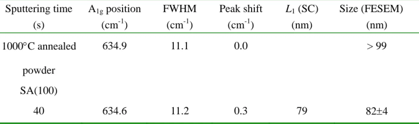
Figure 9, 10 顯示不論是那一個基材,隨線徑減小而變寬且移動的趨勢類似,顯示線徑受基 材的影響很小,主要由奈米金的尺寸決定。Table 1 所列是由模擬 Figure 9, 10 曲線所得線徑值,
結果顯示金膜厚度決定 dewetting 後的顆粒尺寸,進而控制線徑。
Table 1 Values of redshift and line width of the A1g mode for SnO2NW, and the correlated wire size using the SC model. The nanowires are grown on two substrates of SA(100) and (110), sputtered with the Au layer for seeding.
Sputtering time (s)
A1g position (cm-1)
FWHM (cm-1)
Peak shift (cm-1)
L1 (SC) (nm)
Size (FESEM) (nm) 1000C annealed
powder
634.9 11.1 0.0 > 99
SA(100)
40 634.6 11.2 0.3 79 824
11
30 633.9 11.7 1.0 60 633
20 633.4 12.2 1.5 48 474
10 632.4 13.5 2.5 41 414
3 629.9 16.9 5 30 283
SA(110)
40 634.5 11.2 0.4 80 834
30 634.3 12.4 1.6 57 554
20 632.9 12.8 2.0 46 493
10 631.6 14.7 3.3 38 403
3 630.2 16.8 4.7 30 323
Figure 6 TEM images of two facets enclosing a SnO2 nanowire grown on SA(100). For one facet of the nanowire, (a) the HRTEM image and its SAD pattern when viewing along the zone axis [010],
and (b) an enlarged lattice image marked in (a). For the other facet of the nanowire, (c) the HRTEM image and its SAD pattern when viewing along the zone axis [101], and (d) an enlarged lattice image
selected in (c).
12
Figure 7 TEM images of two facets enclosing a SnO2 nanowire grown on SA(110). For one side of the nanowire, (a) a bright field image of the nanowire, (b) the lattice image of the wire and the SAD pattern when viewing along the zone axis [001]. For the other side of the nanowire, (c) the HRTEM
image of zone axis [010], and (d) an enlarged lattice image marked in (c) along with the SAD pattern.
Figure 8 Two schematic diagrams for enclosing facets of the SnO2 nanowire which is grown on (a) SA(100) and (c) SA(110). A cross-sectional view of tilted nanowires, which were grown on (b) SA(100) and (d) SA(110), with their tilt angles marked. The Au sputtering time was 20 s.
13
Figure 9 A1g mode of SnO2NW of various average wire sizes, grown on SA(100). Note the peak shifting and broadening increase with decreasing wire size. Figure 10 A1g mode of SnO2
nanowires of various average wire sizes, grown on SA(110). Note the peak shifting and broadening increase with decreasing wire size. The Au sputtering time is listed in Table 1.
14
2.2 氧化錫奈米線作電化學觸媒支撐研究
氧化錫奈米線徑可作到 30-50 nm,因此提供高比表面積,合適作為電化學觸媒支撐材,若 我們將氧化錫奈米線長於碳紙,則可與現今 PEM 燃料電池架構結合,成為具有觸媒活性的陽 極碳紙,當然前題是具有充份的觸媒活性。研究目標在於,固定鉑觸媒的承載(loading) 0.1 mg cm-2 ,需要還原多少氧化錫與鉑作搭配,能提供充份(最佳)的觸媒活性。
研究結果的答案是還原 54% 氧化錫奈米線成為錫金屬,約 0.17 mg cm-2搭配 0.1 mg cm-2 鉑觸媒,所得到的陽極觸媒碳紙活性最佳。參加 2011 年 HFC2011 會議時,也看到許多加拿大 的研究人員發表類似的研究論文,我們的論文已發表於 2010 年 Electrochimica Acta 。
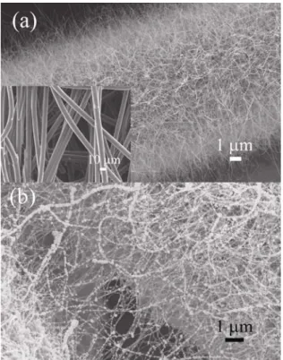
Figure 1(a)所示為兩張 SEM 電鏡圖,沉積氧化錫奈米線之前,光滑的碳纖維線徑約 10 m,
與碳能公司提供資料仿彿,沉積氧化錫奈米線之後,碳纖維表面覆蓋一層濃密的奈米線,線徑 20 - 50 nm ,高密度奈米線僅限於表面的碳纖維,較深入內部的碳纖維上氧化錫奈米線較稀,
約深入 30 m,Figure 1(b)則是還原後再鍍鉑後的影像,氧化錫奈米線已有許多纏繞在一起,
有許多小顆粒散佈在奈米線上,還原前的含氧化錫奈米線之碳布稱作 SnO2NW/CP,還原之後
再鍍上鉑的碳布樣品稱作 Pt/Sn/SnO2NW/CP 。
Figure 10 SEM images of (a) the as-grown SnO2NW encasing a carbon fiber, and the as-received carbon fibers (the inset), (b) the Pt/Sn/SnO2NW/CP of which 0.1 mg cm-2 Pt was electrodeposited on the Sn/SnO2NW/CP which was reduced at 400C for 2.0 h.
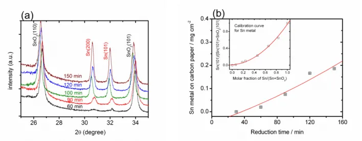
由於還原氧化錫所提供的金屬錫量,乃重要的參數,需要切實瞭解究竟有多少金屬錫量與 鉑觸媒搭配,所以我們用檢量線分析方法,確定個別還原條件下的還原錫金屬量。Figure 11(a) 顯示,氫氣還原 400C 下不同時間可以看到氧化錫及金屬錫繞射線並存的情形,預先配好比例 的化錫及金屬錫混合粉末,量測 Sn(101)/[Sn(101)+SnO2(101)]積分強度比,得到檢量線,如 Figure 11(b)所示,再倒推求得碳布上所還原的金屬錫重(我們假設氧化亞錫存在量可忽略,因
15
為在 X 光繞射圖譜沒有氧化亞錫譜線,只有氧化錫及金屬錫兩相),繪製出 Figure 11(b)。具體 的金屬錫在碳布上含量數值如下(括號內是 400C 還原時間);0.02 (1.0 h), 0.08 (1.5 h), 0.17 (2.0 h), 0.19 (2.5 h) mg cm-2。
Figure 11 (a) XRD patterns of the Sn/SnO2NW/CP samples reduced at 400C for 1.0, 1.5, 1.7, 2.0, 2.5 h; (b) The Sn metal content versus the reduction time in 400 C reduction, and the inset showing
the calibration curve for the integrated intensity ratio of Sn (101) and SnO2 (101) reflections versus the molar fraction of Sn metal in powder mixtures of SnO2 and Sn. No Sn metal reflection was
detected when the reduction time is less than 1.0 h.
Figure 12(a)所示為測試用樣品,長方形旗的碳紙黏在銅線旗桿上,(b)圖是 TEM 明視野圖 其中一支碳纖維附著著氧化錫、金屬錫、鉑觸媒,呈鋸齒形狀,(c) 圖也是 TEM 明視野圖,
呈現尖銳鋸齒的觸媒晶體。
Figure 12 (a) A photograph of the Pt/Sn/SnO2NW/CP working electrode, (b) a TEM image of Pt/Sn catalysts in the sawtooth patches on the carbon fiber, (c) a TEM image showing Pt/Sn catalysts in the
16
polygon form.
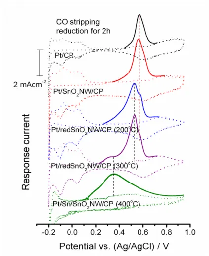
Pt/Sn/SnO2NW/CP 觸媒碳紙重要特性之一,抗 CO 毒化能力,可由一氧化碳剝除實驗結果 CO stripping voltammogram 瞭解,量測時先用一氧化碳氣體將 0.5 M H2SO4電解質飽和,讓電 極在-0.1 V (Ag/AgCl),再放入另一 0.5 M H2SO4溶液(deaerated with N2),掃流循環伏安圖,第 一圈氧化吸附之一氧化碳,第二圈則是乾淨的觸媒表面。Figure 13 所示的一氧化碳氧化電流 以實線表示,其它電雙層電流以虛線表示,其中氧化錫奈米線的還原溫度是重要參數,它將一 氧化碳氧化峰大幅向低電位移動。如果不還原氧化錫奈米線,抗 CO 毒化能力,有無氧化錫奈 米線是一樣的,所以 Pt/C 及 Pt/SnO2NW/CP 的一氧化碳氧化峰電位相同,0.57 V,氧化錫奈 米線被還原後峰電位移動,Pt/redSnO2NW/CP,0.565 V (Pt/SnO2NW/CP), 0.527 V (200 and 300C), 0.355 V (400C)。 此外,也注意一氧化碳氧化峰變得平坦,意謂抗毒化活性分佈廣泛。
Figure 13 CO stripping voltammograms of Pt/CP, Pt/SnO2NW/CP, Pt/redSnO2NW/CP (reduced at 200, 300 C, 2 h), and Pt/Sn/SnO2NW/CP (reduced at 400 C, 2 h). The scan rate is 50 mV s-1. CO pre-adsorption was performed at -0.1 V in the CO saturated electrolyte of 0.5 M H2SO4. Only the COads oxidation current in the first cycle is marked as the solid line, the rest of the first cycle and the current of the second cycle are marked as the dashed line.
17
Figure 14 更進一步比較 400C 的還原時間效應,可見到變化細節,還原時間短於一小時,
明顯的有兩種以上表面存在,細節討論請參考我們的 EA 論文,基本上我們認為還原中有零價、
二價、四價錫,與鉑觸媒共同存在抗毒化,錫的還原對抗毒化有重要貢獻。一氧化碳氧化峰的 起始電位相當重要,代表剝除一氧化碳的開始,愈低代表愈容易剝除毒化的一氧化碳,新生活 性位置,有學者甚至認為新生的活性位置比未毒化位置活性更高,起始電位隨還原時間增加而 減低,代表電極活性更高, 0.341 V (0.0 h), 0.337 V (0.5 h), 0.264 V (1.0 h), 0.098 V (1.5 h), 0.080 V (2.0 h), Table 1 表列完整的結果,一氧化碳氧化峰的峰電位有時有數個,因為還原後數種錫 氧化態存在表面,它們幫助剝除一氧化碳的作用各異。
Figure 14 CO stripping voltammograms of Pt/SnO2NW/CP, Pt/redSnO2NW/CP (400 C, 0.5 h) Pt/Sn/SnO2NW/CP (400 C, 1.0, 1.5, 2.0, 2.5 h). The scan rate is 50 mV s-1. CO pre-adsorption was performed at -0.1 V in the CO saturated electrolyte of 0.5 M H2SO4. Only the COads oxidation current in the first cycle is marked as the solid line, the rest of the first cycle and the current of the second cycle are marked as the dashed line.
Table 1 Characteristic values of COads oxidation potential, electrochemical surface area, and oxidation activity for the Pt/Sn/SnO2NW/CP and Pt/redSnO2NW/CP electrodes with the SnO2NW reduced at 400C. The data were taken from the CO stripping voltammograms.
18 Reduction time
/h
Onset potential /V
Peak potential /V
Surface area*
/m2 g-1
EtOH oxidation current at 0.3 V#
/mA mgPt-1
0.0 0.341 0.565 -- -- 16.6 5.1
0.5 0.337 0.580 0.524 -- 12.9 12.7
1.0 0.264 0.577 0.515 -- 19.2 21.1
1.5 0.098 0.577(w) 0.508 0.330(w) 20.2 14.7
2.0 0.080 -- -- 0.355 24.3 63.5
2.5 0.080 -- 0.508 0.355 13.0 39.8
* The mass specific value of surface area is based on the Pt mass.
# The value of current was measured in the forward scan at 50 mV s-1 in 2.0 M EtOH.
作為陽極觸媒,我們自然關心這個電極的活性表現,Figure 15 比較數個電極的氧化甲醇 及乙醇半電池電流,一如預期,這種 PtSn 電極合適作為乙醇氧化,氧化乙醇的電流特別高,
最高活性的電極是 Pt/Sn/SnO2NW/CP (400 C, 2h)。還原時間若超過 2 h,可能導致比表面積喪 失,因此活性不增反降。
Figure 15 Linear sweep voltammograms for oxidation of (a) 2.0 M MeOH and (b) 2.0 M EtOH in 0.5 M H2SO4. The scan rate is 50 mV s-1. The electrodes are Pt/CP, Pt/SnO2NW/CP, Pt/redSnO2NW/CP (200 and 300 C, 2 h), along with Pt/Sn/SnO2NW/CP (400 C, 2 h).
Figure 16 比較我們所製備的 Pt/Sn/SnO2NW/CP(400 C, 2 h)電極活性及市售的 PtRu/C (Johnson Matthey HiSPEC5000)在氧化甲醇及乙醇的電流與時間關係,Figure 16(a)(b)顯示,
PtRu/C HiSPEC5000 較合適氧化甲醇,而 Pt/Sn/SnO2NW/CP(400 C, 2 h)對氧化乙醇優於 HiSPEC5000,Figure 16(c)的長時間電流亦顯示這樣的趨勢,氧化錫奈米線電化學觸媒,適於 作為乙醇催化電極。
19
Figure 16 Cyclic voltammograms of the optimal Pt/Sn/SnO2NW/CP (400C, 2 h) for oxidation of (a) 2.0 MeOH and (b) 2.0 M EtOH in 0.5 M H2SO4 at sweep rate 50 mV s-1, in comparison with the performance of a commercial catalyst (HiSPEC5000). Activities of the Pt/Sn/SnO2NW/CP and the commercial catalyst are compared in (c) on the chronoamperometric current as well.
參考文獻
1. V. S. Bagotsky, Y. B. Vassilev, J. Electroanal. Chem. 81 (1977) 229.
2. J. B. Goodenough, R. Manoharan, A. K Shukla, K. V. Ramesh, Chem. Mater. 1 (1989) 391.
3. W.-H. Chung, D.-S. Tsai, Y.-M. Chen, Y.-S. Huang, C.-C. Chou, C.J. Liu, Solid State Comm., 146 (2008) 462.
20
三、國科會補助專題研究計畫成果報告自評表
請就研究內容與原計畫相符程度、達成預期目標情況、研究成果之學術或應用價 值(簡要敘述成果所代表之意義、價值、影響或進一步發展之可能性)、是否適 合在學術期刊發表或申請專利、主要發現或其他有關價值等,作一綜合評估。
1. 請就研究內容與原計畫相符程度、達成預期目標情況作一綜合評估
▓ 達成目標
□ 未達成目標(請說明,以 100 字為限)
□ 實驗失敗
□ 因故實驗中斷
□ 其他原因 說明:
2. 研究成果在學術期刊發表或申請專利等情形:
論文:▓已發表 □未發表之文稿 □撰寫中 □無 專利:□已獲得 □申請中 □無
技轉:□已技轉 □洽談中 □無 其他:(以 100 字為限)
7. Wen-Zhong Hung, Wen-Hung Chung, Dah-Shyang Tsai, David P. Wilkinson, Ying-Sheng Huang, (2010) “CO tolerance and catalytic activity of Pt/Sn/SnO2 nanowires loaded on a carbon paper”, Electrochimica Acta, 55, 2116-2122.
8. Adrianas Leonardy, Wen-Zhong Hung, Dah-Shyang Tsai, Chen-Chia Chou, Ying-Sheng Huang, (2009) “Structural features of SnO2 nanowires and Raman spectroscopy analysis”, Crystal Growth & Design, 9, 3958-3963.
9. Shun-Ping Chiao, Dah-Shyang Tsai, David P. Wilkinson, Yi-Ming Chen, Ying-Sheng Huang (2010)“Carbon supported Ru1-xFexSey electrocatalysts of pyrite structure for oxygen reduction reaction”, International J. Hydrogen Energy, 35, 6508-6517.
10. Xie-Hong Jian, Dah-Shyang Tsai, Wen-Hung Chung, Ying-Sheng Huang, Feng-Jiin Liu (2009)
“Pt–Ru and Pt–Mo electrodeposited onto Ir–IrO2 nanorods and their catalytic activities in methanol and ethanol oxidation”, J. Mater. Chem., 19, 1601-1607.
11. Tsu-Yung Jin, Dah-Shyang Tsai, Wen-Hung Chung, Feng-Jiin Liu, (2008) “Electrochemical Behavior of Gel-Derived Lanthanum Calcium Cobalt Ferrite Cathode in Contact with LAMOX Electrolyte”, J. Am. Ceram. Soc. 91 [7] 2217-2222.
12. Wen-Hung Chung, Dah-Shyang Tsai, Yi-Ming Chen, Ying-Sheng Huang, Chen-Chia Chou, Chin-hsin J. Liu (2008) “Thermally decomposed (110) surface of RuO2 single crystal”, Solid State Comm., 146, 462-467.
21
3. 請依學術成就、技術創新、社會影響等方面,評估研究成果之學術或應用價 值(簡要敘述成果所代表之意義、價值、影響或進一步發展之可能性)(以 500 字為限)
氧化錫奈米線作為結構化觸媒的研究,我們開始得很早,希望有廠商能將這 方面技術納入燃料電池中,就目前對台灣廠商的瞭解,他們對綠能有興趣,
也在尋找市場,及通路,或者與國外大廠洽談合作降低風險中,尚無暇顧及 細節如觸媒零組件開發。
展望未來乙醇燃料電池開發成功後,此結構化觸媒有希望應用。
氧化錫奈米線倒是有些感測器應用潛力,但這方面設備建立也得花不少經 費,暫時不考慮深入這方面研究。
22
四、國科會補助專題研究計畫項下出席國際學術會議心得報告
日期:2011 年 11 月 日
一、參加會議經過
氫能及燃料電池 HFC2011 會議,在溫哥華會議中心的 Canada Place 舉行,這個會議除有國際 性討論會之外, 也有商業性質公司與財團法人的技術展示及討論, Panel session 的討論講 員,是政府機構與相關公司,全球主要汽車公司代表, 而口頭與海報發表則多為學校、 國家 實驗室,及科技公司研究人員。 參與國家包括加拿大、美國(尤其是美西)、韓國、中國大陸、
丹麥、德國、巴西、台灣。 加拿大駐台北貿易辦事處的陳幼欣,聯絡所有台灣方面參加人員,
組成台灣代表團,並安排行程。
氫能與燃料電池議題上,美國與加拿大顯然不同調,美國只有加州、奧勒岡州、華盛頓州 這一地區的人,了解及參與氫能工作,其它美國地區較支持電池科技,主要是鋰離子電池, 但 是歐洲方面則不這樣看問題,他們認為氫能燃料電池應該繼續發展,加拿大站在歐洲陣營這邊,
對於氫能投資極為重視。
星期日下午領取會議手冊後 立即參加 Canadian Research Perspectives,有四位加拿 大的學府教授談潔淨能源與未來展望。
四位教授提供不同氫能問題面的思考, R. Chahine (Univ. Quebec), S. Holdcroft
(Simon-Fraser Univ), V. Birss (Univ. Calgary), N. Djilali (Univ.Victoria) 四位學者 中,只有最後的 Djilali 討論較無趣的電腦與氫能管理方面。
計畫編號 NSC 98-2221-E-011-028-MY2
計畫名稱 氧化錫奈米線成長及其電化學觸媒支撐材應用研究 出國人員
姓名 蔡大翔 服務機構
及職稱 台灣科技大學化工系
會議時間
2011 年 5 月 15 日至 2011 年 5 月 20 日
會議地點
加拿大溫哥華(Vancouver, Canada)
會議名稱
(中文)氫能及燃料電池 HFC2011 會議
(英文)Hydrogen+Fuel Cells 2011
發表論文 題目
(中文)硒化釕電化學觸媒的氧還原活性及氮摻雜碳的促進活性 效果
(英文) [S23.4] Oxygen reduction activity of the ruthenium selenide electrocatalyst and promoter effects of its N-doped carbon support
23
R. Chahine 強調氫的儲存,演講重點在於氫並不單純只是純氫分子,包括 Bio fuel,
photosynthetic fuel, electrofuel (將 electricity of renewable energy 轉化成碳氫化合 物), 這些燃料可能比單純 H2 更有競爭力,畢竟使用氫的燃料電池車只比油電混合車效率高 出 15%而以。而 FCV 的可跑距離長(long driving range),價格高,優缺點兩項特色,將決定 它在汽車市場的成敗。 另外,他也提出一個根本性的問題,光合作用可以沒有二氧化碳參加 反應嗎? 他沒有答案,僅提出問題。
S. Holdcroft 強調燃料電池的時間順序問題,因為價格高昂,燃料電池普及化已推遲,研究 焦點主要找到取代白金的辦法 並且使用高表面積一維材料作為支撐材,或是不需要外部加濕 的膜材,他已 NRC 所支持計畫,所合成的材料說明加拿大研究能力。
Viola Birss 以固態氧化物燃料電池 SOFC 為演講重點,強調這型的燃料電池,適合加拿大廣 大無電力網到達的偏遠地區,所產生的高溫廢熱,充份利用能提高效率,但 SOFC 價格仍高,
也需要降低設備投資,另外也介紹一些他們最近對抗硫、抗磷、其它不純物的陽極材料, 例 如 NiAl2O4 。順便介紹卡加利市(Calgary)為基地 Versa 公司,生產 SOFC。
[S4.4] Overcoming cell cracking arising from Ni oxidation in anode-supported SOFCS – presented by Prof. Viola Birss, Univ. Calgary
Dr. Birss 的訓練似乎在材料學方面, 他討論目前在固態燃料電池上對陽極汙染的做法後續 影響,目前楊極的材料主要以鎳金屬與釔摻雜氧化鋯組成,但使用天然氣、合成氣、或是液化 瓦斯, 都有硫及磷的汙染, 清除方法最簡單的就是用空氣陡衝 (air purge),提供氧氣,高 溫下氧化硫及磷,但這會引起鎳金屬氧化,然後,應力作用下陽極剝離電解質,甚至使電解質 開裂,他報告主要以電鏡分析為主,然後解釋為何,低溫高氧分壓下鎳金屬氧化,不良的結構 影響最小。
[S4.5] Cost-effective deposition of dense ceria barrier layer in solid oxide fuel cell processed at 700oC – Dr. Yongsong Xie (IFCI)
討論他以噴霧法合成 SOFC 的陰極與電解質間氧化鈰阻抗層, 合成法與效果,主持人問他為何 不用 IFCI 著名的火焰噴霧塗膜法合成, 他表示這種方法較便宜。
[S9.1] Development of the short-side-chain PFSA ionomer feeding high-temperature PEFC industrial and research activity worldwide – Matthias Gebert (Solvay Solexis) 討論如何改善 Nafion 膜材高分子的長側鏈,將其改短之後,有助於將需要的濕度降低,期待 未來能無需外部加濕。
[S9.2] On-line gas measurements within PEM fuel cell flow fields by electric arc emission spectroscopy and Raman spectroscopy – Hans Betterman
(Heinrich-Heine-University of Duesseldorf)
討論利用線上的拉曼光譜及 Arc Emission Spectroscopy 分析 H2, O2, N2, CO, H2O 分子濃度,
了解 PEM FC 內部運作, 例如可能的膜材裂縫導至氫氣濃度突然增加,利用光譜術迅速獲得數
24
據。
[S8.4] Polybenzimidazole based HT-PEMFC :recent progress in material development and durability evaluation – Qingfeng Li (Techical Univ Denmark)
[S8.5] TDP: A project on the national scale for the development of improved PEM catalyst and supports – Alan Guest (NRC IFCI)
[S14.1] Performance and durability of high performance MEAs for high temperature PBI fuel cells – Thomas Steenberg (Danish Power Systems)
[S14.2] Studies on tungsten carbides as high temperature PEMFC catalyst supports – Weimin Zhu (NRC IFCI)
[S14.5] Operating PEM fuel cells on higher temperatures (opportunities and challenges) – Peter Beckhaus (ZBT Gmbh, Germany)
這五篇論文都討論 PBI+H3PO4膜的高溫燃料電池,PBI 是特殊高分子,用於太空人服裝的材料 能耐 300C, 後被 Case-Western Reserve Univ 用於高溫 PEM FC 電解質膜,目前普遍用於 150 – 180oC PEM FC,但演講者都經歷更嚴重的白金觸媒腐蝕, 磷酸易被洗出, 碳支撐材氧化,等
耐久性的問題,所以提高 100oC 問題轉換成耐久性的問題。也有數篇討論用其他碳化物或氧
化物取代碳支撐材,企圖克服高溫 PEM FC 的碳支撐材氧化問題,但成果乏善可陳,例如 Tungsten carbide 支撐材即是一例;雖然導電能力很好,但是白金觸媒活性在高溫下快速失 活,因為高溫也促進腐蝕。
[S18.1] Non-precious metal ORR catalyst – Are we closing the performance gap? Dr.
Piotr Zelenay (Los Alamos National Lab)
主講人 Dr. Zelenay 高調表示含有鐵鈷的氮摻雜碳, 酸性溶液中表現接近白金,有更好的活 性,不同前驅物, 對活性影響多 他主要提到兩種前驅物 Polyaniline 及 Cyanamide- derived N-doped carbon,其中 Cyanamide-Fe-C catalyst 活性、穩定俱佳,他認為碳的結 構如洋蔥微結構對活性有益。但他對於活性來源並未作任何說明,只用單電池的表現說明其觸 媒活性甚高。我事後有去恭賀他,他的態度反轉趨保守,他說"I hope that I have
accomplished this."究竟如何,恐怕有待其正式論文發表。
[18.3] Nanopillar metal oxides as high surface area support for oxygen reduction catalysts – Ryan Tucker (Univ. of Alberta)
此研究為 high temperature PEM FC 尋找觸媒與觸煤支撐材,他用 Pt/NbOx/glass carbon,其 中氧化鈮是一維材料,以其數據看來,氧化鈮一維材料的支撐作用並不很好。這個領域,我們 執行奈米計畫時也努力過,加國有不少研究計畫朝此方向努力。
[23.1] Nanosized cubic V8C7 as effective Pt support for oxygen reduction reaction –Pei Kang Shen (Sun Yat-Sen Univ)
因為碳支撐材有氧化問題,沈教授研發 VC 化合物取代碳,效果不錯,經過水熱法合成的 VC 微 粉支撐材,能協助白金觸媒的催化活性。
25
[S23.4] Oxygen reduction activity of the ruthenium selenide electrocatalyst and promoter effect of its N-doped support – Dah-Shyang Tsai (NTUST)
我們的研究以黃鐵礦結晶的硒化釕為主題,將近三年的研究作一總結,此一結構增加於觸媒的 穩定性,我們更將氮摻雜碳輔助硒化釕觸媒活性,提升其活性,由於沒有類似的想法,觀眾相 當感興趣,IFCI 的 Ryan Baker 及丹麥 Qingfeng Li 會後仍作相當廣泛的討論。
[S31.2] Ovonic renewable hydrogen – low temperature reformation technology to produce hydrogen from renewable feedstock – Willy Mays (Energy Conversion Devices)
[S31.5] Co-production of clean electricity and green hydrogen from waste derived biogas – Alakh Prasard (Quadrogen Power Systems)
經由厭氧發酵,廚餘生產 Bio gas 作為燃料,若未經純化,只能用於耐髒的 SOFC,其它沼氣 及掩埋場(landfill gas),主要成份也是甲烷,商轉公司已推出利用這些生質氣體的製程與實 例,討論集中製程的重組及純化問題 。
[S31.3] Development of dense membranes for hydrogen purification from coal gasification stream. Dr. U. (Balu) Balachandran, Argonne National Lab.
Balachandran 研發高於 500oC 使用的氫氣分離膜已有相當長的一段時間,以這篇報告的成熟 度觀之,氫氣分離膜以 Pd 薄膜披覆於多孔 YSZ 支撐的結構,操作表現已達到相當穩定,但顯 然成本相當高,80 m 厚的緻密 Pd 薄膜,價格不會便宜到那裡。他們研究設備主要做成雙套 管的構造,加壓的煤氣,含有氫、甲烷、阿摩尼亞、一氧化碳、二氧化碳、硫化氫,經過氫氣 分離膜後,500, 550, 600C 長時間測試,實驗數據顯示氫氣含量高達 98%以上,由於鈀僅容 氫氣通過,氫氣含量理論上是 100%,觀眾提此問題,講者表示滲漏來自於套管密封部份,也 就是 Sealing 部份仍未能做得盡善盡美,雖然這個題目已做約 15 年之久,但密封的問題仍難 解決。
我們發表的會議論文放在附件。
二、與會心得
總結此次會議心得,在工程論文發表方面,因為與 UBC 的 Wilkinson 教授平日有合作,發 表結果在會議上比較受到重視,Wilkinson 教授的學生來主持會議,發表後,前來討論的 人多,所以跟國外學者合作,雖然沒有計畫運作,僅是溝通訊息,仍是有利的,畢竟我們 一年僅有一次出國機會,消息的靈通程度,遠不如他們,我們唯一優於他們的,是學生實 驗較努力,可惜近年此一優勢也在消失中。在業界參訪方面,參觀工業實驗室,看到加國 工程人員,切實量測分析,氫儲槽的尺寸、強度、耐久性,與其它國家聯絡,共同制定標 準,踏實準備進入新能源紀元的基礎,深深感到慚愧,我們的工作似乎總是開會,嘴上說 說,回去電腦就打出長長的文件,準備工作就完成,有誰會做這些切割、塗層、閥件設計 的基礎工作?似乎,沒人會,也不在乎,反正到時送人出去學就好。如果,我們一直這樣
![Figure 6 TEM images of two facets enclosing a SnO 2 nanowire grown on SA(100). For one facet of the nanowire, (a) the HRTEM image and its SAD pattern when viewing along the zone axis [010],](https://thumb-ap.123doks.com/thumbv2/9libinfo/9125644.410039/15.892.87.755.95.488/figure-images-facets-enclosing-nanowire-nanowire-pattern-viewing.webp)
![Figure 7 TEM images of two facets enclosing a SnO 2 nanowire grown on SA(110). For one side of the nanowire, (a) a bright field image of the nanowire, (b) the lattice image of the wire and the SAD pattern when viewing along the zone axis [001]](https://thumb-ap.123doks.com/thumbv2/9libinfo/9125644.410039/16.892.258.644.119.504/figure-enclosing-nanowire-nanowire-nanowire-lattice-pattern-viewing.webp)