行政院國家科學委員會專題研究計畫 成果報告
微機電裝置應用於微衛星姿態控制之運動彈性動力學研究 (第 2 年)
研究成果報告(完整版)
計 畫 類 別 : 個別型
計 畫 編 號 : NSC 99-2218-E-011-004-MY2
執 行 期 間 : 100 年 01 月 01 日至 100 年 10 月 31 日 執 行 單 位 : 國立臺灣科技大學自動化及控制研究所
計 畫 主 持 人 : 郭永麟
計畫參與人員: 碩士班研究生-兼任助理人員:DEWANTORO 碩士班研究生-兼任助理人員:FERIYONIKA 碩士班研究生-兼任助理人員:伍建安 碩士班研究生-兼任助理人員:戴承武
公 開 資 訊 : 本計畫涉及專利或其他智慧財產權,2 年後可公開查詢
中 華 民 國 100 年 12 月 01 日
中 文 摘 要 : 近年來微衛星已被定位成低成本的衛星系統。由於微衛星體 積小、重量輕,它也帶來工程技術上重大的挑戰。Li 等學者 在 2001 年曾提出一個微機電的致動裝置,它是一個『偽』轉 輪(pseudo-wheel)。事實上它是由數個小尺寸的樑(beam)所 組成,而每個樑均是由電熱材料(electro-thermal
materials)所製成。若在微衛星的三軸上皆裝有該微機電裝 置,且藉由輸入電壓開或關的控制造成樑的變形,可以實現 微衛星的姿態控制。本研究計畫案是要藉由前述的微機電裝 置達到微衛星的姿態控制,並對該微衛星系統精確地建模、
分析、模擬和控制,以驗證本研究計畫所提出的方法。本報 告分為兩部分,第一部分是探討該微機電致動器之彈性動力 特性,第二部分是根據第一部分的分析結果設計微衛星姿態 控制器。
中文關鍵詞: 微衛星;衛星姿態動力與控制;偽轉輪。
英 文 摘 要 : In recent years, micro spacecrafts have been
considered as the next logical step in the evolution of capable, low-cost spacecraft systems. Since these spacecrafts are very small in size and weight, they pose unique engineering challenges. Li et al. (2001) has proposed a MEMS actuator (called pseudo-wheel) for an attitude stabilization of a spacecraft. This actuator comprises of four small beams, and each beam is made up of electro-thermal materials. If the MENS devices are individually installed on each principal axis of the micro spacecraft, by switching on or off the input voltage to yield the deformation of the beams, the attitude of the spacecraft can be
accomplished. The main goal of the research project is to precisely model, analysis, simulate, and control the attitude motion of the micro spacecraft by using the MENS device in order to verify the proposed approach. This report is divided into two parts. The first part studies the kineto-dynamics of the MEMS actuator, and the second part proposes the attitude control of miniature spacecraft based on the analysis results of the first part.
英文關鍵詞: miniature spacecraft; attitude dynamics and control; pseudowheel.
行政院國家科學委員會補助專題研究計畫 ▉ 成 果 報 告
□期中進度報告 微機電裝置應用於微衛星姿態控制之運動彈性動力學研究
計畫類別:▉個別型計畫 □整合型計畫
計畫編號:NSC 99-2218-E-011-004-MY2
執行期間:2011 年 1 月 1 日至 2012 年 10 月 31 日 執行機構及系所:國立臺灣科技大學 自動化及控制研究所
計畫主持人:郭永麟 共同主持人:
計畫參與人員:Feriyonika,G.Dewantoro,伍建安,戴承武
成果報告類型(依經費核定清單規定繳交):□精簡報告 ▉完整報告
本計畫除繳交成果報告外,另須繳交以下出國心得報告:
□赴國外出差或研習心得報告
□赴大陸地區出差或研習心得報告
□出席國際學術會議心得報告
□國際合作研究計畫國外研究報告
處理方式:除列管計畫及下列情形者外,得立即公開查詢
□涉及專利或其他智慧財產權,□一年▉二年後可公開查詢 中 華 民 國 100 年 11 月 24 日
中文摘要
近年來微衛星已被定位成低成本的衛星系統。由於微衛星體積小、重量輕,
它也帶來工程技術上重大的挑戰。Li 等學者在 2001 年曾提出一個微機電的致動 裝置,它是一個『偽』轉輪(pseudo-wheel)。事實上它是由數個小尺寸的樑(beam) 所組成,而每個樑均是由電熱材料(electro-thermal materials)所製成。若在微衛星 的三軸上皆裝有該微機電裝置,且藉由輸入電壓開或關的控制造成樑的變形,可 以實現微衛星的姿態控制。本研究計畫案是要藉由前述的微機電裝置達到微衛星 的姿態控制,並對該微衛星系統精確地建模、分析、模擬和控制,以驗證本研究 計畫所提出的方法。本報告分為兩部分,第一部分是探討該微機電致動器之彈性 動力特性,第二部分是根據第一部分的分析結果設計微衛星姿態控制器。
關鍵字:微衛星;衛星姿態動力與控制;偽轉輪。
Abstract
In recent years, micro spacecrafts have been considered as the next logical step in the evolution of capable, low-cost spacecraft systems. Since these spacecrafts are very small in size and weight, they pose unique engineering challenges. Li et al.
(2001) has proposed a MEMS actuator (called pseudo-wheel) for an attitude stabilization of a spacecraft. This actuator comprises of four small beams, and each beam is made up of electro-thermal materials. If the MENS devices are individually installed on each principal axis of the micro spacecraft, by switching on or off the input voltage to yield the deformation of the beams, the attitude of the spacecraft can be accomplished. The main goal of the research project is to precisely model, analysis, simulate, and control the attitude motion of the micro spacecraft by using the MENS device in order to verify the proposed approach. This report is divided into two parts.
The first part studies the kineto-dynamics of the MEMS actuator, and the second part proposes the attitude control of miniature spacecraft based on the analysis results of the first part.
Keywords: miniature spacecraft; attitude dynamics and control; pseudowheel.
Acknowledgment
The study was sponsored with a grant, NSC-99-2218-E-011-004-MY2, from National Science Council, Taiwan.
目錄
中文摘要 ... I Abstract...II Acknowledgment ... III 目錄 ... IV 圖目錄 ...V 表目錄 ... VI
Part I. Study of a Piezoelectric Actuator... 1
1. Introduction to Piezoelectric Actuator ... 1
2. Modeling of a piezo-actuator ... 2
3. Validation of static bimorph model ... 6
4. Dynamic analysis of the piezo-actuator... 8
5. Summary for Part I... 12
Part II. Attitude Control Using Pseudowheels... 13
6. Introduction to Attitude Control Using Pseudowheels ... 13
7. Attitude control strategy of rotation sequences ... 14
8. Formulation of equations of motion ... 18
9. Implementation procedure of the attitude control strategy ... 21
10. Implementations of the attitude control strategy... 22
10.1 Implementations of all possible rotation sequences ... 23
10.2 Reductions of the applied voltages to the pseudowheels ... 26
10.3 Closed-loop attitude control ... 29
11. Summary for Part II ... 32
12. Conclusions ... 32
References ... 33
附件一:國科會補助專題研究計畫成果報告自評表 ... 36
附件二:論文發表情形 ... 38
圖目錄
Fig 1 A MENS actuator – a pseudo-wheel... 3
Fig 2 Laminate beams on an MEMS... 3
Fig 3 A hub-bimorph model... 6
Fig 4 A hub-bimorph finite element model... 6
Fig 5 A classical piezoelectric bimorph [20] ... 8
Fig 6 Longitudinal modes... 9
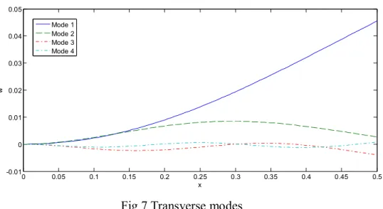
Fig 7 Transverse modes ... 10
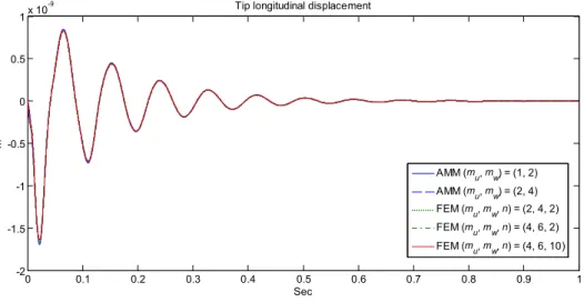
Fig 8 Tip longitudinal displacement...11
Fig 9 Tip transverse displacement...11
Fig 10 Rotating angle of hub ...11
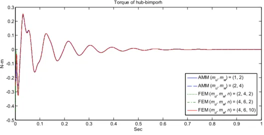
Fig 11 Generated torque ... 12
Fig 12 A pseudowheel with four piezoelectric bimorphs ... 14
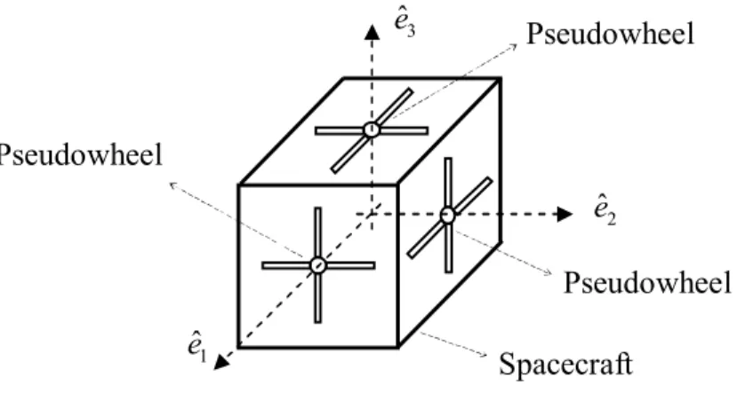
Fig 13 A spacecraft with pseudowheels... 14
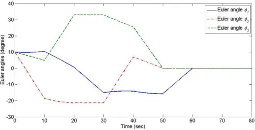
Fig 14 Time responses of Euler angles 3-2-1 initiated at (10, 10, 10) ... 17
Fig 15 Time responses of Euler angles 3-2-1 initiated at (110, 130, 150)... 18
Fig 16 A simplified single-axis spacecraft-pseudowheel model... 18
Fig 17 Time responses of tip displacement of bimorph and rotating angle of spacecraft based on 500-volt input ... 21
Fig 18 Attitude control strategy ... 22
Fig 19 (a) Time responses of Euler angles and (b) applied voltages based on one set of rotation sequence (2,-3,1,-2,3,-1) ... 23
Fig 20 (a) Time responses of Euler angles and (b) applied voltages based on three sets of rotation sequence (3,-1,2,-3,1,-2)... 25
Fig 21 (a) Time responses of Euler angles and (b) applied voltages... 26
Fig 22 (a) Time responses of Euler angles and (b) applied voltages based on 7 steps of rotation sequence (2,-3,1,-2,3,-1) ... 27
Fig 23 (a) Time responses of Euler angles and (b) applied voltages based on 3 steps of 3 sets of rotation sequence (3,-1,2,-3,1,-2) ... 28
Fig 24 Closed-loop attitude control strategy... 29
Fig 25 (a) Time responses of Euler angles and (b) applied voltages using the closed-loop control strategy with constraint based on rotation sequence (3,-1,2,-3,1,-2) ... 30
Fig 26 (a) Time responses of Euler angles and (b) applied voltages for the systems with the gravity gradient torques using the closed-loop control strategy based on three sets of rotation sequence (3,-1,2,-3,1,-2)... 32
表目錄
Table 1 Static transverse deformation of the bimorph... 7 Table 2 Natural frequencies of the piezo-actuator ... 9 Table 3 Comparisons of Examples 10.1 to 10.5 ... 28
Part I. Study of a Piezoelectric Actuator
1. Introduction to Piezoelectric Actuator
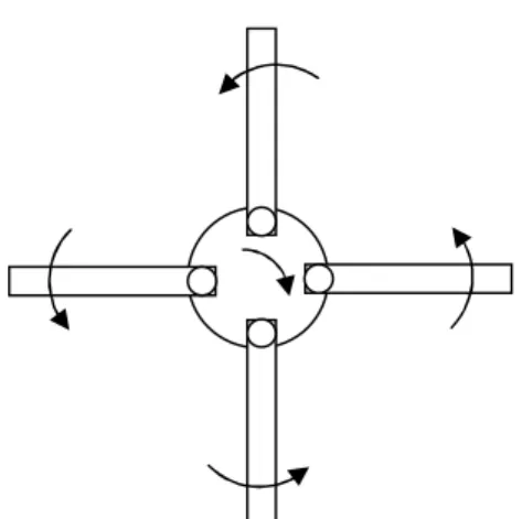
Attitude stabilization and control of spacecraft is a significant issue to complete a space mission. Li et al. [1] presented a MENS actuator, called a pseudo-wheel shown in Fig 1, for an attitude control of spacecraft. This actuator comprises of four small beams; each beam is made up of two different electro-thermal materials of unequal thermal expansion coefficients. Using the bi-metallic or bimorph effect [2] when a voltage is applied on these beams, they undergo deformation due to thermal expansion. The relationship between applied voltage and beam deformation depends on the design of pseudo-wheel and the beam made of electro-thermal materials.
Mankane et al. showed that the transverse deformation of an electro-thermal actuator changes from 0.2 to 2% for the range of the voltage from 5 to 20 volts [3]. It illustrates that a small voltage can provide large deformation. However, when voltage is off they come back to their original configurations. By properly regulating the deformation of these beams, it is possible to control the attitude of the spacecraft. For an illustration, if the four small beams undergo a clockwise rotation, the spacecraft rotates in counter-clock-wise direction in order to conserve the system angular momentum.
Piezoelectric bimorphs are the oldest basic piezoelectric structures. Smits et al.
gave a comprehensive and detailed historical review of the applications of piezoelectric bimorphs [4]. Their formulations were validated by experimental, analytical, or numerical approaches [5-18]. Generally speaking, they provided various one-, two-, and three-dimensional solutions for multilayer beams [9-14]. Since the exact solutions are available only for some regular shapes with some simple boundary conditions, the finite element models based on the Hamilton’s variational principle for piezoelectric structures are commonly applied [15-20].
For the purpose of attitude control of spacecraft, it is necessary to understand the kineto-elasto-dynamics of the so-called pseudo-wheel made of piezoelectric materials, proposed by Li et al. [1]. However, although there were numerous researches of piezoelectric structures, a limited number of literatures presented kineto-elasto-dynamics related to their studies. Therefore, this study will emphasize the kineto-elasto-dynamic modeling of the pseudo-wheel and present analysis results for the applications of attitude control of micro spacecraft. The pseudo-wheel model is simplified as a hub attached with a bimorph, called a piezo-actuator in this paper.
An applied voltage excites the flexible deformation of the bimorph, which includes the longitudinal and transverse displacements. The flexible deformation yields the rigid body rotation of the hub, which can be performed attitude control when the
pseudo-wheel attached to a micro spacecraft. Although the proposed model is highly nonlinear, and the flexible and rigid body motions are coupled, it can be solved by the assumed mode method and the finite element method. To obtain dynamic responses, it is necessary to perform numerical integration. However, it is time-consuming, and the solution accuracy depends on the number of modes for the assumed mode method and the number of elements for the finite element method. Therefore, for application purpose, it is important to study the kineto-elasto-dynamics of the pseudo-wheel.
This report is organized as follows. First of all, a nonlinear dynamic model of a piezo-actuator is derived. Secondly, the nonlinear dynamic model of the pseudo-actuator is simplified as a static model, which is verified by comparing with some literature results. Thirdly, the proposed dynamic model is analyzed. Finally, some conclusions follow.
2. Modeling of a piezo-actuator
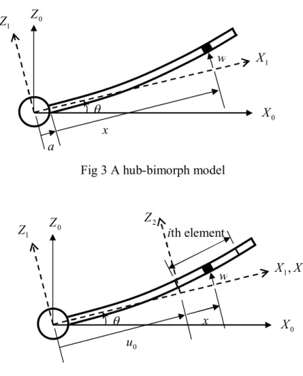
A pseudo-wheel is simplified as a hub attached with a bimorph, called a piezo-actuator shown in Fig 3. The hub is assumed as a rigid body, and the bimorph is considered as a beam made of piezoelectric materials. Three coordinate systems are defined in Fig 3, where the pair(
X
0,Z
0) represents the reference coordinates,) ,
(
X
1Z
1 are the bimorph body-fixed coordinates, and (X
2,Z
2) are the bimorph element coordinates. The hub-bimorph has a rigid body rotating angle with respect to the reference coordinateX . The modeling of the bimorph is based on
0 Euler-Bernoulli beam theory. The deformation of the bimorph includes the longitudinal and transverse displacements. Also, the rigid body rotation of the hub-bimorph is excited by the vibration of the bimorph. Therefore, the position, velocity, and acceleration vectors of any point on the bimorph with respect to the bimorph-fixed coordinate system (X
1,Z
1) are respectively given ask w i u x a
r( )ˆ ˆ
(1) k
u x a w i w u
r(
)ˆ[
( )]ˆ (2) kw u u x a w i u x a w w u
r [
2
2( )]ˆ [
( ) 2
2 )]ˆ (3)
where iˆ and kˆ are the unit vectors along the
X - and
1Z -directions, respectively;
1u and w are the longitudinal and transverse displacements, respectively; a is the
radius of the hub;x is the longitudinal position; is the rigid body rotating angle
of the bimorph.Fig 1 A MENS actuator – a pseudo-wheel
Fig 2 Laminate beams on an MEMS actuator
The vibration of the bimorph is excited by an applied voltage
E along the
3Z
1 direction only. The linear constitution equations of the piezoelectric materials are given as3 31 1 11
1 c S e E
T E (4)
3 33 1 31
3 e S E
D
S (5)where
T and
1S are the stress and strain along the
1X direction, respectively;
1D
3 andE are the electric displacement and the electric field along the
3Z direction,
1 respectively;c
11S is the elastic coefficient;e is the piezoelectric constant;
31 is
33S the dielectric permittivity coefficient.The kinetic energy, the potential energy, the work done by the inertial force can be formulated respectively as
h l
b I Ar rdx
T 0
2
2 1 2
1
(6)
V V
b
S T dV E D dV
U
1 1 3 32 1 2
1 (7)
l
b dx
x x w a l a A
W 0
2 2
2
2[( ) ( ) ]( ) }
2 {1 2
1
(8)where
I is the moment of inertia of the hub;
h ,
A, l, and V are the density, the cross section area, the length, and the volume of the bimorph, respectively. Thus, the Lagrangian can be written as follows.b b
b
U W
T
L
(9)The modeling goal of the piezo-actuator aims to formulate the governing equations for the assumed mode method (AMM) and the finite element method (FEM). Thus, the longitudinal and transverse displacements can be respectively approximated as
u
N
u
,w N
w
(10)where
N and
uN are row vectors composing of assumed mode functions for the
w AMM or shape functions for the FEM, and is column vector composing of the
variables associated with the assumed modes for the AMM or nodal variables for the FEM.By applying the Lagrange’s equation, the governing equations can be expressed as
] [ } ]{
[A d B (11)
where
Td}
{ (12)
b T
T h T
TB I M A F I
F B A M
2 0
0 0
1 0 0
2 ) ] (
[
(13)
0 0
0 0
0 0 0 2 0
0 2 0
0
2 ) (
2
} )
{(
) ] (
[
B M A A
V F K F A M B
B B
T T
T T
(14)
A l NuTNu NwTNw dx
M0
0( ) (15)
A l NuTNw NwTNu dx
B0
0( ) (16)
cEA lNuxTNuxdx cEI lNwxxT Nwxxdx
K 11 22 0
23 0 11
0 (17)
A l a L u x NwxT Nwxdx
A 0
2 1 2
0 [( ) ( ) ]
2
1
(18)
e bh lNwxxdx F0 31 0
4
1 (19)
A l u x Nwdx
F1
0( 1 ) (20)
A l u x Nudx
F2
0( 1 ) (21)3 ) (u12l u1l2 1l3 A
Ib
(22)Note that
u
1a
andu
1a
u
0 for the AMM and for the FEM, respectively.Quantity
u is the distance from the rotating center to the left end of the element
0 (SeeFig 4). Also, the FEM needs the assembling of all element equations to obtain the global finite element equations.
In order to study the torque generated by the piezo-actuator, based on Eq. (3), the torque is given by
b T
T
q
A r r dx B M M F F F I
T
0
0
2
0
1
2
2
2
2
(23) Eq. (11) is not only for the piezo-actuator but also for a slewing beam, whose input signal is a prescribed rotating motion of the hub. Thus, Eq. (11) can be re-arranged as a set of linear time-varying equation:F K Z
M
(24)where
M
0M
(25)) (B0 B0T
Z
(26)0 0 0
2( M A ) K
B
K
(27)Fig 3 A hub-bimorph model
Fig 4 A hub-bimorph finite element model
3. Validation of static bimorph model
In order to further study the relationship between the deformation of the bimorph and the applied electric field, the static analysis of the bimorph is performed.
Applying the Hamilton’s principle to Eq. (9) leads the governing equation and the boundary conditions as
11SIbwxxxx 0
c (28)
0
| )
(c11SIbwxx Mb
wx 0l , c11SIbwxxx
w|0l0 (29) whereI is the second moment of area of the bimorph;
bM is the bending
b moment due the inverse piezoelectric effect, which is Mb e31bh2E3/4 (b is the width of the bimorph.)For a cantilever bimorph, the boundary conditions are given as 0
) 0 (
w
,w
x(0)0,w
xxx( l
) 0, c11SIbwxx(l)Mb (30)X
1Z
0Z
1 X
0a
x
w
2 1, X
X Z
0Z
1 x X
0w ith element
u
0Z
2Thus, the exact transverse displacement of the bimorph and the tip displacement are expressed as
2
2 11
) 1
(
x
I c x M
w
b S
b
, 2
2 11
) 1
(
l
I c l M
w
b S
b
(31)
The applied electric field for a thin bimorph can be expressed as
h
V V
E
3 0 0/ , whereV is the applied voltage. Then, the ratio of the tip
0 transverse displacement to the applied voltage is expressed as2 11 31 0
) )(
( ) 3 (
h l c e V
l w
S (32)
which shows that the tip transverse displacement is proportional to the materials property ratio e31/c11S based on the same applied voltage and the same bimorph dimension.
Based on the formulations presented in Sec 2, by eliminating the dynamic terms, Eq. (11) can be reduced as
0 0
0 FV
M
(33)which can be applied to the finite element method (FEM) and the assumed mode method (AMM).
A classical PVDF bimorph consists of two identical PVDF uniaxial beams with opposite polarities shown in Fig 5 was presented [16]. The same problem is solved by the FEM and AMM, and 1-Volt voltage is applied across the thickness of the bimorph.
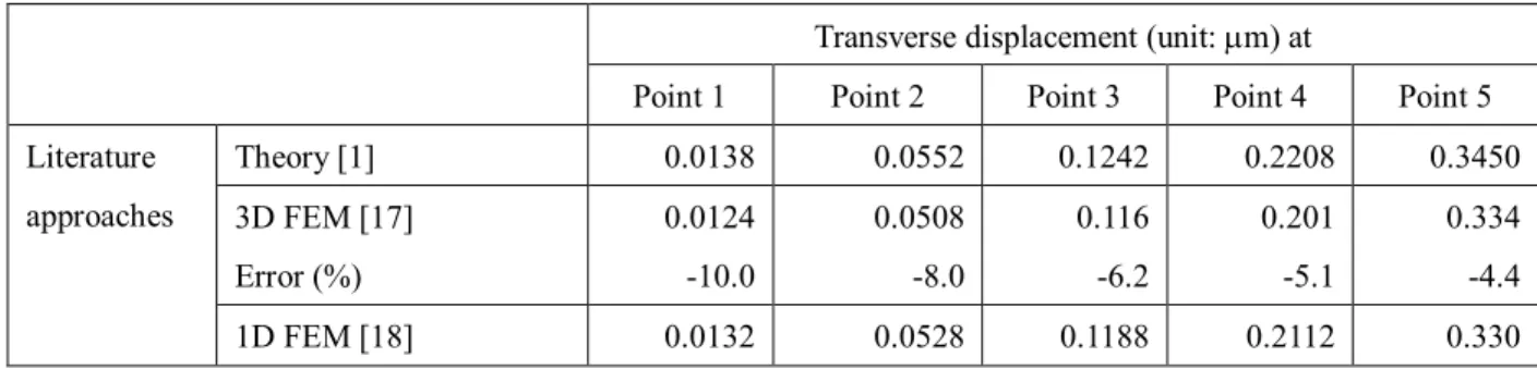
Table 1 lists the transverse displacements and the errors at five particular points shown in Fig 5. The results are also compared with those from literatures. Based on the exact solution shown in Eq. (31), the transverse displacement is a quadratic polynomial. Since the AMM adapts the mode shapes as approximated functions composing of sinusoidal and hyperbolic functions, it is necessary to include more modes in order to obtain a more accurate approximated solution. In contrast, the FEM adapts a cubic polynomial as shape functions, so even a one-element mesh can closely reach the exact solution.
Table 1 Static transverse deformation of the bimorph
Transverse displacement (unit: m) at
Point 1 Point 2 Point 3 Point 4 Point 5
Theory [1] 0.0138 0.0552 0.1242 0.2208 0.3450
3D FEM [17]
Error (%)
0.0124 -10.0
0.0508 -8.0
0.116 -6.2
0.201 -5.1
0.334 -4.4 Literature
approaches
1D FEM [18] 0.0132 0.0528 0.1188 0.2112 0.330
Error (%) -4.3 -4.3 -4.2 -4.4 -4.4 2D FEM (1 layer) [20]
Error (%)
0.0134 -2.9
0.0540 -2.2
0.122 -1.6
0.218 -1.4
0.342 -0.9 2D FEM (10 layer) [20]
Error (%)
0.0132 -4.3
0.0540 -2.2
0.121 -2.4
0.218 -1.4
0.341 -1.2 4-mode AMM
Error (%)
0.0133 -3.465
0.0557 0.9432
0.1237 -0.4221
0.2213 0.2139
0.3423 -0.7941 8-mode AMM
Error (%)
0.0139 0.4163
0.0552 -0.0038
0.1241 -0.0728
0.2207 -0.0601
0.3443 -0.2008 Presented
approaches
1-element FEM Error (%)
0.0138 2.2810-12
0.0552 2.2810-12
0.1242 1.1110-12
0.2208 1.0910-12
0.3450 1.0010-12
Fig 5 A classical piezoelectric bimorph [20]
4. Dynamic analysis of the piezo-actuator
The transverse displacement and the rigid body rotation of the bimorph are assumed as small variations. By neglecting the nonlinear terms in Eq.
), the linear model is given as
3 2 0
1
0]{ } { } [ ]{ } { }
[M
F T
K
q F E (34)0 ) (
} { }
{F1 T
Ih C0
(35)Based on the above equations, the natural frequencies of the piezo-actuator are shown in Table 2. The piezo-actuator includes a longitudinal motion, a transverse motion, and a rigid body rotation. The natural frequency of the rigid body rotation is zeros. Thus, Table 2 lists the natural frequencies of the longitudinal and transverse modes by using the AMM and the FEM. The natural frequencies of the longitudinal modes are higher than those of the first four transverse modes. Thus, it is expected that the transverse modes would mainly dominate the motion of the pizeo-actuator. To
compare the results in Table 2, the AMM provides faster rate of convergence than the FEM. Fig 6 and 7 show the first four longitudinal and transverse mode shapes.
Table 2 Natural frequencies of the piezo-actuator
Longitudinal modes (rad/s) Transverse modes (rad/s)
Methods NDOF
Mode 1 Mode 2 Mode 1 Mode 2 Mode 3 Mode 4
AMM (2,4) 6 1.0682104 4.2619104 71.775 205.39 502.42 962.20 AMM (4,4) 8 1.0682104 3.2046104 71.775 205.39 502.40 962.10 AMM (6,6) 12 1.0681104 3.2045104 71.775 205.38 502.39 962.05 FEM (2,4,2) 6 1.0958104 3.8280104 71.874 206.41 607.64 1720.9 FEM (2,4,4) 12 1.0750104 3.3914104 71.782 205.62 506.20 975.10 FEM (2,4,8) 24 1.0699104 3.2519104 71.775 205.40 502.69 964.22 FEM (4,6,2) 12 1.0682104 3.2072104 71.775 205.39 503.55 976.05 FEM (4,6,4) 22 1.0682104 3.2045104 71.775 205.38 502.39 962.10 FEM (4,6,8) 42 1.0682104 3.2045104 71.775 205.38 502.38 962.07
: For the AMM, the values in the brackets of the first column refer to the numbers of longitudinal and transverses modes; for the FEM, the first two values in the brackets of the first column refer to the degrees of shape functions of approximated longitudinal and transverse displacements, and the last value refers to the number of elements.
0 0.05 0.1 0.15 0.2 0.25 0.3 0.35 0.4 0.45 0.5
-0.05 0 0.05 0.1 0.15
x
u
Mode 1 Mode 2 Mode 3 Mode 4
Fig 6 Longitudinal modes
0 0.05 0.1 0.15 0.2 0.25 0.3 0.35 0.4 0.45 0.5
-0.01 0 0.01 0.02 0.03 0.04 0.05
x
w
Mode 1 Mode 2 Mode 3 Mode 4
Fig 7 Transverse modes
A constant voltage 100 Volt is applied to the bimorph, and it produces longitudinal and transverse deformations as well as the rigid body rotation of the hub.
Fig 8 to 11 show the dynamic responses of the tip longitudinal displacement, the tip transverse displacement, the rotating angle of the hub, and the torque generated by the bimorph, respectively. There are five cases in these figures. The first two cases are the AMM; the first and fourth cases are the FEM; the last case is a reference solution by using the FEM with a ten-element discretization. To compare these five cases, the responses of the tip transverse displacement shows that case 4 provide an excellent agreement with the reference solution; the tip longitudinal displacement and the rotating angle of the hub does not show much differences; the torque generated by the bimorph has slight differences before 0.01 seconds. To examine the steady state values of these figures, the tip longitudinal displacement and the torque are zeros, but the transverse motion of the bimorph generates a rigid body rotation of the hub. Thus, the voltage applied to the bimorph can be used as a control signal to regulate the motion of the hub.
0 0.1 0.2 0.3 0.4 0.5 0.6 0.7 0.8 0.9 1 -2
-1.5 -1 -0.5 0 0.5
1x 10⁻⁹
Sec
m
Tip longitudinal displacement
AMM (mu, mw) = (1, 2) AMM (mu, mw) = (2, 4) FEM (mu, mw, n) = (2, 4, 2) FEM (mu, mw, n) = (4, 6, 2) FEM (mu, mw, n) = (4, 6, 10)
Fig 8 Tip longitudinal displacement
0 0.1 0.2 0.3 0.4 0.5 0.6 0.7 0.8 0.9 1
0 0.5 1 1.5 2 2.5 3 3.5x 10⁻³
Sec
m
Tip transverse displacement
AMM (mu, mw) = (1, 2) AMM (mu, mw) = (2, 4) FEM (pu, pw, n) = (2, 4, 2) FEM (pu, pw, n) = (4, 6, 2) FEM (pu, pw, n) = (4, 6, 10)
Fig 9 Tip transverse displacement
0 0.1 0.2 0.3 0.4 0.5 0.6 0.7 0.8 0.9 1
-0.25 -0.2 -0.15 -0.1 -0.05 0
sec
deg
AMM (m u, m
w) = (1, 2) AMM (mu, mw) = (2, 4) FEM (p
u, p
w, n) = (2, 4, 2) FEM (p
u, p
w, n) = (4, 6, 2) FEM (pu, pw, n) = (4, 6, 10)
Fig 10 Rotating angle of hub
0 0.1 0.2 0.3 0.4 0.5 0.6 0.7 0.8 0.9 1 -0.5
-0.4 -0.3 -0.2 -0.1 0 0.1 0.2 0.3
Sec
N-m
Torque of hub-bimporh
AMM (m u, m
w) = (1, 2) AMM (m
u, m w) = (2, 4) FEM (mu, mw, n) = (2, 4, 2) FEM (mu, mw, n) = (4, 6, 2) FEM (m
u, m
w, n) = (4, 6, 10)
Fig 11 Generated torque
5. Summary for Part I
This paper presents elasto-dynamic studies of a piezo-actuator, which can be applied to attitude stabilization and control of micro spacecraft. The piezo-actuator is designed as a hub attached with a bimorph. Although there are numerous researches related to this model, it is limited number of literatures to analyze its kineto-elasto-dynamics. The proposed model is highly nonlinear but can be solved by the finite element method and the assumed mode method. An applied voltage excites the flexible deformation of the bimorph, which includes the longitudinal and transverse displacements. Also, the flexible deformation yields the rotating angle of the hub, which can be attached on a micro spacecraft to perform attitude control.
Since the model highly nonlinear and the flexible and rigid body motions are coupled, it is time-consuming to obtain dynamic responses by numerical integration. Also, the computing time depends on the number of modes for the assumed mode method or the number of elements for the finite element method. To validate the proposed model, it is simplified as a static bimorph, and the deflection results are compared with some literatures. The results show that the proposed model solved by the finite element method can provide more accurate solutions. To examine the nature frequencies, the assumed mode method can provide more accurate solutions than the finite element method. However, to examine the response of the tip deflection, the finite element method employing quintic shape functions can provide more accurate solutions.
Part II. Attitude Control Using Pseudowheels
6. Introduction to Attitude Control Using Pseudowheels
During the last two decades, miniature spacecraft, including pico-spacecraft and femto-spacecraft, have been considered as the next logical step in the evolution of capable, low-cost spacecraft systems [23-25]. Since these spacecrafts is very small in size and weight, they pose unique engineering challenges. The micro-/nano-technologies can be one of the major solutions for the challenges [26-27].
However, these low cost, low mass, and low power devices, such as MEMS gyros, MEMS accelerometers, and MEMS digital thrusters, limited space applications.
Moulton and Anathasuresh [28] considered an MEMS actuator based on electrothermal compliant (ETC) mechanism. The ETC mechanism works on the principle of nonuniform Joule heating of various sections of the actuator to generate deflections. The amount of deflection is controlled by the applied voltage while the direction of deflection is regulated by changing the electrical connection from series to parallel or vice versa. Li et al. examined a MEMS actuator, called a pseudowheel, for attitude stabilizations of spacecraft [29]. This actuator comprises multiple small beams attached to the spacecraft, and each beam is made of two different electro-thermal materials of unequal thermal expansion coefficients. Using the bi-metallic or bimorph effect when a voltage is applied on these beams, they undergo deformation due to thermal expansion [30]. Thus, when an external voltage is applied to the bimorph, it would bend and the hub produces a counter-direction rotation due to the conservation of angular momentum. Therefore, the rotation motion can be regulated by switching the external voltage, so the actuation is bounded and fully-reversed. Koh et al. discussed the issues of controllability and developed motion planning algorithms for such a system, and they used approximate methods to develop two algorithms for controlling satellite orientation [31-32]. Kuo et al. employed the inverse kinematics and developed an algorithm to determine the optimal trajectory by minimizing the actuating energy [33].
The aforementioned researchers investigated the feasibility of the pseudowheel applied to attitude control of spacecraft. However, all of them assumed the pseudowheel as a rigid body hinged on the spacecraft. This paper presents a feasible approach to fulfill the attitude control based on the pseudowheels. The main contributions of this paper is summarized as follows: (1) Due to the flexibility of the bimorph, the modeling of the spacecraft-pseudowheel system takes the inverse piezoelectric effect into account, and this improve the modeling accuracy; (2) Since not every rotation sequence can provide a solution, this paper presents an approach to archive all rotation sequences; (3) The vibrations of bimorphs are excited by large
applied voltages, which are limited by the specifications of voltage amplifiers, and this paper demonstrates how to meet the requirements; (4) The attitude error caused by the gravity gradient torques is compensated by a closed-loop attitude control strategy. This paper is organized as follows: the attitude control strategy is presented in Sec 7, and the equations of motion of the spacecraft-pseudowheel system are derived in Sec 8; the implementation of the attitude control strategy is summarized in Sec 9, and some examples are demonstrated in Sec 10; some conclusions are presented in Sec 11.
Fig 12 A pseudowheel with four piezoelectric bimorphs
Fig 13 A spacecraft with pseudowheels
7. Attitude control strategy of rotation sequences
An attitude control actuator, called a pseduwheel, is illustrated in Fig 12, and the attitude reorientation of spacecraft can be performed by mounting pseudowheels on each principal axis of spacecraft shown in Fig 13, where ˆe , 1 ˆe and 2 ˆe are the unit 3 vectors along the three body-fixed principal axes. There are two limitations to fulfill the achievement of attitude control. One is that activation and deactivation should be applied at different times, and the other is that the pseudowheel cannot perform a
ˆe 1
ˆe 2
ˆe 3 Pseudowheel
Pseudowheel Pseudowheel
Spacecraft
full-circle rotation. To overcome these limitations, Li et al. [7] used a sequence rotation caused by deflecting pseudowheels about three orthogonal axes to produce a net orientation change. This method can be illustrated by employing large angle rotation sequence about three principal axes of the spacecraft as follows:
I R R R R R R
R
w][ ][ ][ ][ ][ ][ ][ 3 2 1 3 2 1
(36)
where Ri is the rotation matrix with respect to the ith axis, and the minus sign represents the reverse rotation. Thus, the positive and negative signs represent activation and deactivation of pseudowheels, respectively. Therefore, a sequence rotation with a condition that two consecutive rotations are not about the same axes can perform an attitude reorientation.
Since the attitude reorientation can be achieved by using various rotation sequences, three types of rotation sequences were presented [11]:
Type A: [Rw][Rj][Ri][Rj][Ri] (37)
Type B:
] ][
][
][
][
][
[ ] [
] ][
][
][
][
][
[ ] [
] ][
][
][
][
][
[ ] [
] ][
][
][
][
][
[ ] [
i j k j k i w
i j k j i k w
i j k i k j w
i j k i j k w
R R R R R R R
R R R R R R R
R R R R R R R
R R R R R R R
(38)
Type C:
] ][
][
][
][
][
[ ] [
] ][
][
][
][
][
[ ] [
i j i k j k w
i j i k j k w
R R R R R R R
R R R R R R R
(39) where the subscripts i, j and k can be 1, 2 or 3, but they must be different. Type A represents two-axis rotation sequences, and types B and C are three-axis. Type B has four formats, which represent three different axes on the first three rotations. Type C has two formats, which represent that the first and third axes are the same. Therefore, there are 24, 192 and 48 rotation sequences respectively for types A, B and C, and the total number of possible rotation sequences is 264.
The rules of the attitude control strategy of the pseudowheels are summarized as follows: (1) One applies four or six successive rotations based on the three types of rotation sequences; (2) There is only one axis performing the rotation during the same time. (3) Each rotation axis should include a positive rotation and a negative rotation.
Thus, a rotation matrix representing spacecraft attitude reorientation should be equal to the rotation matrix based on a prescribed rotation sequence, and this can be expressed as
)]
, , ( [ )]
, , (
[
![Fig 5 A classical piezoelectric bimorph [20]](https://thumb-ap.123doks.com/thumbv2/9libinfo/9126779.411043/17.892.127.830.102.695/fig-a-classical-piezoelectric-bimorph.webp)