國立台灣大學理學院化學系 碩士論文
Department of Chemistry College of Science
National Taiwan University Master's Thesis
氟取代苯並噻二唑型小分子於 有機太陽能電池之合成、性質與應用
Syntheses, Properties, and Applications of Small Molecules with Fluorinated Benzothiadiazole for Organic
Solar Cells
陳建儒 Chien-Ju Chen
指導教授:汪根欉 博士 Advisor: Ken-Tsung Wong, Ph.D.
中華民國 104 年 7 月
July 2015
中文摘要
小分子太陽能電池因具有分子結構明確、每批品質較一致之優勢,故近年吸 引相當多領域投入研究。
先前的文獻指出,在電子予體中引入氟原子,可以同時降低分子的最高占有 分子軌域與最低未占有分子軌域之能階。而降低之能階有助於太陽能電池獲得較 高之開路電壓。故在本篇論文中,我們設計並合成了具予體-受體-受體 (D-A-A) 架 構之含氟電子予體。其分別以噻吩與苯環為架橋,並在苯並噻二唑上引入朝內或 朝外之氟原子,可得 DTCTiFBT,DTCToFBT,DTCPiFBT 及 DTCPoFBT。四 個分子的最大吸收波長在 500-600 nm,且有良好的吸收效率。相較於其對照組,
四個分子皆表現些微紅移之吸收光譜,以及較低之能階。將其與電子受體材料 C60
共蒸鍍,並調變適當的膜厚及混合比例製作太陽能電池元件。四個分子之表現皆
較未引入氟的對照電子予體優異。在與 C60 共蒸鍍的元件中,以噻吩為架橋的
DTCToFBT/C60 最佳化元件結構可得到 0.83 V 之開路電壓,6.85 mA/cm2之短路 電流,以及 3.28% 之光電轉換效率。而以苯環為架橋的 DTCPoFBT 最佳化元件
結構可得到 0.88 V 之開路電壓,6.50 mA/cm2 之短路電流,以及 3.62% 之光電轉
換效率。本論文展示了 D-A-A 架構之含氟電子予體之結構與性質對應。
Abstract
In recent years, small-molecule organic solar cells (SMOSCs), because of their well-defined structure and batch-to-batch reproducibility, are under intense investigations.
We anticipate that the introduction of fluorine atom onto a donor molecule can lower the highest occupied molecular orbital (HOMO) and lowest unoccupied molecular orbital (LUMO) of the donor, giving the SMOSC device a larger open circuit voltage (Voc). In this thesis, four molecules configured as donor-acceptor-acceptor (D-A-A) were synthesized and characterized. Two electron donating moieties, namely ditolyaminothiophene or ditolyaminophenylene were respectively connected to an electron deficient cyano group, via F-substituted [2,1,3]benzothiadiazole (FBT) to give DTCTiFBT, DTCToFBT, DTCPiFBT, and DTCPoFBT. Four molecules showed slightly red-shifted absorption and lowered HOMO and LUMO level as compared to those of the non-fluorinated counterparts. After fabrication with fullerene C60 as the active layers in SMOSCs, all molecules showed better performance compared to the non-fluorinated counterparts. Among all, thiophene-bridged DTCToFBT/C60 device exhibited a Voc of 0.83 V, a short circuit current density (Jsc) of 6.85 mA/cm2, and a fill factor (FF) of 0.58, achieving a power conversion efficiency (PCE) of 3.28%.
Pheneylene-bridged DTCPoFBT/C60 device exhibited a Voc of 0.88 V, a Jsc of 6.50 mA/cm2, and a FF of 0.63, achieving a PCE of 3.62%. A clear structure-property relationship has been established.
Contents
中文摘要 ... i
Abstract ... ii
Index of Figure ... iv
Index of Table ... v
Index of Scheme ... vi
Chemical Structure Index ... vii
Chapter 1 Introduction ... 1
Chapter 2 DTCTiFBT and DTCToFBT ... 11
2-1 Syntheses ... 11
2-2 Optical Properties ... 12
2-3 Electrochemical Properties ... 13
2-4 Theoretical Calculations ... 14
2-5 Crystal Structures and Packings ... 17
2-6 Thermal Properties ... 18
2-7 Photovoltaic and Electrochemical Impedance Characteristics ... 19
Chapter 3 DTCPiFBT and DTCPoFBT ... 21
3-1 Syntheses ... 21
3-2 Optical Properties ... 21
3-3 Electrochemical Properties ... 23
3-4 Theoretical Calculations ... 23
3-5 Crystal Structures and Packings ... 26
3-6 Thermal Properties ... 27
3-7 Photovoltaic and Electrochemical Impedance Characteristics ... 28
Conclusions ... 30
Experiment Session ... 31
Syntheses and Materials. ... 31
General Experiment ... 37
References ... 40
Appendix A 1H and 13C NMR Spectra ... 43
Appendix B TGA and DSC Thermogram ... 51
Appendix C X-ray Crystallography Data ... 56
Index of Figure
Figure 1-1. The spectrum of solar radiation at Earth's surface. ... 2 Figure 1-2. Aromatic and quinoid resonance forms for some conjugated polymers
and their relative population in ground state. ... 4 Figure 2-1. Absorption spectra of DTCTiFBT (triangles) and DTCToFBT
(diamonds) in (a) CH2Cl2 solutions and (b) vacuum deposited thin films. .... 12 Figure 2-2. Cyclic voltammograms of DTCTiFBT and DTCToFBT. ... 13 Figure 2-3. DFT-optimized geometries for DTCTiFBT and DTCToFBT. ... 15 Figure 2-4. Isodensity surface plots of the HOMO (green) and LUMO (red) of
DTCTiFBT and DTCToFBT... 17 Figure 2-5. Crystal structures of DTCTiFBT in molecular packing. ... 18 Figure 2-6. (a) J-V curves and (b) EQE spectra for DTCTiFBT (triangles),
DTCToFBT (diamonds), and DTCTB (pentagons) for C60-based OPV. ... 20 Figure 3-1. Absorption spectra of DTCPiFBT (square) and DTCPoFBT (circle)
in (a) CH2Cl2 solutions and (b) vacuum deposited thin films. ... 22 Figure 3-2. Cyclic voltammograms of DTCPiFBT and DTCPoFBT. ... 23 Figure 3-3. DFT-optimized geometries for DTCPiFBT and DTCPoFBT. ... 24 Figure 3-4. Isodensity surface plots of the HOMO (green) and LUMO (red) of
DTCPiFBT and DTCPoFBT. ... 26 Figure 3-5. Crystal structures of DTCPiFBT and DTCPoFBT in molecular
packing. ... 27 Figure 3-6. (a) J-V curves and (b) EQE spectra for DTCPiFBT (square), and
DTCPoFBT (circle) for C60-based OPV. ... 29
Index of Table
Table 1-1. Electrochemical parameters and device performance of several
fluorinated electron donors. ... 8 Table 2-1. Photophysical and electrochemical parameters for DTCTiFBT,
DTCToFBT, and DTCTB. ... 13 Table 2-2. Dipole moment parameters for DTCTiFBT, DTCToFBT, and
DTCTB. ... 16 Table 2-3. TD-DFT calculated oscillator strengths, absorption wavelengths,
molecular orbital compositions, and transition characters for DTCTiFBT and DTCToFBT. ... 16 Table 2-4. Thermal parameters for DTCTiFBT, DTCToFBT, and DTCTB. ... 19 Table 2-5. Photovoltaic parameters for DTCTiFBT, DTCToFBT, and DTCTB
with OPV structure: ITO / MoO3 / dye: C60 (x nm) / C60 (y nm) / BCP / Al. . 20 Table 3-1. Photophysical and electrochemical parameters for DTCPiFBT,
DTCPoFBT, and DTCPB. ... 22 Table 3-2. Dipole moment parameters for DTCPiFBT, DTCTPoFBT, and
DTCPB. ... 25 Table 3-3. TD-DFT calculated oscillator strengths, absorption wavelengths,
molecular orbital compositions, and transition characters for DTCPiFBT and DTCPoFBT. ... 25 Table 3-4. Thermal parameters for DTCPiFBT, DTCPoFBT, and DTCPB. ... 28 Table 3-5. Photovoltaic parameters for DTCPiFBT and DTCPoFBT with OPV
structure: ITO / MoO3 / dye: C60 (x nm) / BCP / Al. ... 29
Index of Scheme
Scheme 1-1. Small molecule electron donors for OSCs achieving PCE over 8%. . 5 Scheme 1-2. Fluorinated electron donors for OSCs achieving PCE over 6%. ... 6 Scheme 1-3. Chemical structures of several fluorinated electron donors. ... 7 Scheme 1-4. Chemical structures and performance of DTCTB and DTCPB. ... 9 Scheme 1-5. Four D-A-A electron donors synthesized and characterized in this
thesis. ... 10 Scheme 2-1. Synthetic route for FBTCN, DTCTiFBT, and DTCToFBT. ... 11 Scheme 3-1. Synthetic route for DTCPiFBT and DTCPoFBT. ... 21
Chemical Structure Index
Target Compounds
Intermediates
Chapter 1 Introduction
Energy issue has raised increasing attention over the past decades. Since fossil fuels are expected to be used up within 21th century, several types of alternative energy, including solar energy, biofuel, wind power, tidal power, and geothermal energy, are currently under intensive investigation. It is beautiful to extract electricity directly from the sun, which is clean, safe, and crucial for our lives. Thus, different kinds of photovoltaic devices (PVs) have emerged and become a prominent subject in the past few decades.1 Silicon-based solar cells, because of their well-studied properties, long stability, and high power conversion efficiency (PCE), have been widely used for generating electricity. Despite several advantages of silicon-based solar cells, there are some drawbacks, like high production cost and related environment impact, which have impelled us to develop new types of PVs continuously.1 Among all, organic solar cells (OSCs) are one of the possible solutions.
The fascinating features of OSCs are the potential of large-area and roll-to-roll fabrication, light-weight and flexible devices, lower cost, and low impact to environment. Nowadays, different kinds of OSCs have been investigated. The best-known designs of device are dye-sensitized solar cells (DSSCs) and organic thin-film solar cells. DSSCs have been well studied and the maxima PCEs are steadily over 10%.2 Organic thin-film solar cells comprise an electron acceptor, which is usually fullerene derivatives, and an organic electron donor. When an electron donor absorbs a photon, an electron in the highest occupied molecular orbital (HOMO) is excited to the lowest unoccupied molecular orbital (LUMO). The photogenerated exciton diffuses within the electron donor towards the interface to the electron acceptor. If the energy level difference between the electron donor and the electron
acceptor is larger than the exciton binding energy, usually 0.3–1.0 eV,3 charge transfer from the donor molecule to the acceptor molecule occurs. The electron is transferred to the acceptor molecule via the energetically favorable driving force, resulting in a polaron pair. After dissociation, the hole stays and transports on the electron donor, which is thus called p-type material, whereas the electron travels on the electron acceptor, thus called n-type material. The polarons can transport to electrodes and deliver photocurrent. The donor-acceptor heterojunction plays an important role in device performance. Since the diffusion length of excitons in organic electronic materials is typically within 20 nm,4 large interface area is essential for the excitons to reach the heterojunction interface. In bulk heterojunction cells (BHJ), an electron donor and an electron acceptor are cast simultaneously. Hence, two components are allowed to interpenetrate, creating huge extension of interface area. Consequently, BHJ is the most widely used architecture for organic thin-film solar cells.3-4
An electron donor should capture photons from solar radiation efficiently to provide high photocurrent. The most intense irradiance region of solar spans 400–700 nm at Earth's surface (Figure 1-1).5 To gain power conversion efficiency, the optical absorption of an electron donor should span visible range and extend to near-infrared region. Luckily, powerful synthetic methods have been developed to invent electron donors with appropriate properties.
Figure 1-1. The spectrum of solar radiation at Earth's surface.
Judicious design of electron donors is crucial for controlling their bandgaps and thus utilizing solar radiation. As shown in Figure 1-2, four polyaromatic conjugated polymers, namely polyphenylene, poly(phenylenevinylene), polythiophene, and polyisothianaphthene, are chose to illustrate the relationship between aromaticity and bandgap.6 In ground state, all polymers exhibit two forms with nondegenerate energy:
aromatic and quinoid form. In aromatic form, the π-electrons are confined in each ring to gain resonance stabilized energy, resulting in extra stability. In quinoid form, however, the π-electrons are delocalized and the aromaticity is destroyed, which is thus energetically less stable than aromatic form. Consequently, there is more population in aromatic form for the first three polymers. The large bandgap (3.2 eV) of polyphenylene results from the high resonance stabilized energy of benzene (36 kcal mol-1), whereas the relatively low aromaticity of thiophene (29 kcal mol-1)7 gives a small bandgap (2.0 eV) for polythiophene. For poly(phenylenevinylene), insertion of double bonds can dilute the overall aromaticity and thus reduce the bandgap (2.5 eV). To increase the quinoid population effectively, fused rings are adopted to maintain the aromaticity in quinoid form. The higher resonance stabilized energy of benzene than thiophene lets polyisothianaphthene tend to favor quinoid form to keep the aromaticity of benzene. To sum up, higher aromaticity components result in larger bandgap; however, the aromaticity can be utilized in fused rings to increase the quinoid population. In this thesis, an electron-withdrawing [2,1,3]benzothiadiazole moiety with high quinoidal character was utilized in conjugated backbone to facilitate π-electron delocalization.8
Figure 1-2. Aromatic and quinoid resonance forms for some conjugated polymers and their relative population in ground state.
After fabrication into photovoltaic devices, there are three key parameters to determine the power conversion efficiency of a PV: the open-circuit voltage (Voc), short-circuit current density (Jsc), and fill factor (FF). The fill factor is defined as the following equation: FF =VMPP ∗ JMPP
Voc ∗ Jsc , where MPP is the abbreviation of the maximum power point. As a result, power conversion efficiency can be written as follows: PCE =Voc ∗ Jsc ∗ FF
Pin , where Pin denotes the input power. In order to obtain high Jsc, PV devices should possess large shunt resistance (Rsh) and small series resistance (Rs).9 On the other hand, since Voc is mainly determined by the energy difference between the HOMO of an electron donor and the LUMO of an electron acceptor,10 lower HOMO of an electron donor may realize higher Voc. FF implies morphology in the active layer, and the possibility the photogenerated carriers can be extracted.
In bulk heterojunction cells, electron donors can be roughly classified into two categories: small molecule and polymer. Small molecule organic solar cells
(SMOSCs), because of their well-defined structure and batch-to-batch reproducibility compared to polymer solar cells (PSCs), are attracting more attention. Several small molecules were employed as electron donors and achieved PCE over 8% (Scheme 1-1). DR3TSBDT, featuring benzodithiophene (BDT) as the electron-donating unit for solution-processed BHJ, showed a certified PCE of 9.9%.11 From our previous research, vacuum-deposited DTDCPB solar cell performed a maximum PCE of 8.2%, which is one of the highest PCE reported for asymmetric dipolar electron donors.12 A cascade architecture non-fullerene OSC comprising an electron donor α-6T and two electron acceptors, SubPc and SubNc, reached a remarkable PCE of 8.4%.13 Furthermore, a tandem OSC comprising DTTz for visible absorption and DTDCTB for near-infrared absorption could achieve a high PCE of 9.2%.14 Such results indicate that SMOSCs can yield high PCE and are worth further investigation.
Scheme 1-1. Small molecule electron donors for OSCs achieving PCE over 8%.
Recently, there are extensive studies of the introduction of heteroatoms on electron donors, one of which is a fluorine atom. Some representative chemical structures and device performance of fluorinated electron donors are shown in Scheme 1-2. Dithienosilole (DTS) centered p-DTS(FBTTh2)2,15 connecting with fluorobenzothiodiazole (FBT) as electron withdrawing group (EWG), performed a maximum PCE of 9.0%,16 which is prominently higher than the PCE 0.2% of the non-fluorinated counterpart 4.17 BIT-4F-T, comprising difluorobenzothiadiazole (dFBT) as EWG, delivered a maximum PCE of 8.1%.18 Polymer BHJ utilizing PTB7 as an electron donor, which features a fluorinated-thienothiophene moiety, could obtain an impressive PCE of 9.2%.19 All-polymer BHJ, utilizing both fluorinated electron donor PBDTT-TT-F and electron acceptor P(NDIDT-FT2), yielded a maximum PCE of 6.7%,20 which is among the highest PCE reported all-polymer solar cells. Based on these investigations, fluorinated EWGs are promising components to access high power conversion efficiency for OSCs.
Scheme 1-2. Fluorinated electron donors for OSCs achieving PCE over 6%.
Many studies revealed the relationship between fluorination and energy level.
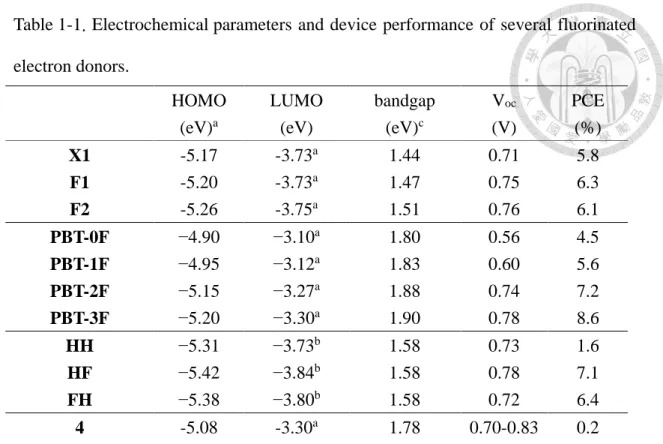
Some representative series of fluorinated electron donors are illustrated in Scheme 1-3 and summarized in Table 1-1. As the introduction of fluorine atom(s), both HOMO and LUMO energy levels were lowered for all electron donors in three conditions: (1) the decrement of HOMO is larger than that of LUMO, resulting in larger bandgap, like X1 series21 and PBT-0F series.22 (2) The decrement of HOMO is equal to that of LUMO, resulting in equal bandgap, like HH series23 and p-DTS(FBTTh2)2 series.15,
17 (3) The decrement of HOMO is smaller than that of LUMO, resulting in smaller bandgap, like PBnDT-HTAZ series.24 In all conditions, the lowered HOMO can contribute to high Voc. Furthermore, in the third condition, smaller bandgap may lead to bathochromic absorption, which is beneficial for pursuing higher Jsc. However, the third condition is generally less reported.
Scheme 1-3. Chemical structures of several fluorinated electron donors.
Table 1-1. Electrochemical parameters and device performance of several fluorinated electron donors.
HOMO (eV)a
LUMO (eV)
bandgap (eV)c
Voc
(V)
PCE (%)
X1 -5.17 -3.73a 1.44 0.71 5.8
F1 -5.20 -3.73a 1.47 0.75 6.3
F2 -5.26 -3.75a 1.51 0.76 6.1
PBT-0F −4.90 −3.10a 1.80 0.56 4.5
PBT-1F −4.95 −3.12a 1.83 0.60 5.6
PBT-2F −5.15 −3.27a 1.88 0.74 7.2
PBT-3F −5.20 −3.30a 1.90 0.78 8.6
HH −5.31 −3.73b 1.58 0.73 1.6
HF −5.42 −3.84b 1.58 0.78 7.1
FH −5.38 −3.80b 1.58 0.72 6.4
4 -5.08 -3.30a 1.78 0.70-0.83 0.2
p-DTS(FBTTh2)2 -5.12 -3.34a 1.78 0.81 7.0
PBnDT-HTAZ -5.29 -2.87a 2.42 0.70 4.3
PBnDT-FTAZ -5.36 -3.05a 2.31 0.79 6.8
a calculated from the cyclic voltammogram. b optical bandgap + HOMO. c LUMO – HOMO.
Though there is a clear relationship between fluorination and the decrement of both HOMO and LUMO, such conclusion is typically based on polymers. There are fewer literatures about small molecules. Most of them are based on centrosymmetric configurations, e.g. D2-A1-D1-A1-D2 or D2-A2-D1-A1-D1-A2-D2 architecture. Research based on asymmetric configuration, such as D-A-A type, is relatively rare. This thesis provided examples for the second and the third condition based on D-A-A small molecules.
From our previous study of electron donors for SMOSCs, DTCTB and DTCPB, in which two electron-donating ditolylaminophenyl and ditolylaminothienyl moieties were respectively connected to an electron-withdrawing cyano group through another
electron-withdrawing [2,1,3]benzothiadiazole moiety, performed a maximum PCE of 4.4% and 6.4% on C70-based devices (Scheme 1-4). It is noteworthy that the fill factor is very high, especially for DTCPB (FF = 0.65). Organic photovoltaic (OPV) devices with high FF have a high Rsh and a low Rs, suggesting the morphology after blended with fullerenes is very beneficial for reducing the internal loss of current produced by the devices. Encouraged by the promising results, we decide to introduce a fluorine atom onto BT moieties of DTCTB and DTCPB as a pendant group to alter energy levels. Since the atomic weight is 19 Da for a fluorine atom, the change of molecular weight (MW) is small for a D-A-A molecule with MW 400–500 Da. We expect that replacing a hydrogen atom with a fluorine atom will make little change to the benign morphology while providing additional interactions or steric hindrance.
Scheme 1-4. Chemical structures and performance of DTCTB and DTCPB.
In this thesis, four donor-acceptor-acceptor (D-A-A) structured electron donors were synthesized and characterized, namely DTCTiFBT, DTCToFBT, DTCPiFBT, and DTCPoFBT (Scheme 1-5). The difference in aromaticity of benzene and thiophene along with the different position of the inserted fluorine atom can lead to different performances and meaningful discussions. Their corresponding BHJ devices and solid film properties were fabricated and measured by Prof. Jiun-Haw Lee and Mr.
Yi-Ze Hsiao at the Graduate Institute of Photonics and Optoelectronics, National Taiwan University. For comparison, this thesis also included the non-fluorinated
counterparts, DTCTB and DTCPB, synthesized and characterized by Dr. Hao-Chun Ting and Mr. Chia-Hsun Chen. The density functional theory (DFT) and time-dependent density functional theory (TD-DFT) theoretical calculations of six molecules were performed at CAM-B3LYP/6-311G(d,p) level by Dr. Shu-Hua Chou.
Scheme 1-5. Four D-A-A electron donors synthesized and characterized in this thesis.
Chapter 2 DTCTiFBT and DTCToFBT
2-1 Syntheses
The synthetic route of FBTCN, DTCTiFBT, and DTCToFBT is illustrated in Scheme 2-1. FBTBr was adopted as the starting material and synthesized according to the previous literature15. FBTBr underwent Palladium-catalyzed cyanation to give the key intermediate FBTCN in 39% yield. Stille coupling of 4-(N,N-ditolylamino)-1-(tri-n-butylstannyl)thiophene (dtat-tin) and FBTCN afforded DTCTiFBT in 77% yield. For DTCToFBT, dtat-tin was reacted with FBTBr via Stille coupling to afford DTToFBTBr in 67% yield, which subsequently underwent Palladium-catalyzed cyanation to give DTCToFBT in 89% yield. From infrared (IR) spectra analyses, DTCTiFBT and DTCToFBT exhibit distinct absorption of nitrile group in 2222 and 2227 cm-1 respectively, while DTToFBTBr shows no absorption in 2210–2260 cm-1.25 Their chemical structures were further confirmed via nuclear magnetic resonance spectroscopy (NMR) and mass spectroscopy.
Scheme 2-1. Synthetic route for FBTCN, DTCTiFBT, and DTCToFBT.
2-2 Optical Properties
Optical properties of DTCTiFBT and DTCToFBT are shown in Figure 2-1.
Their corresponding properties are summarized in Table 2-1. In solution, both molecules show slightly bathochromic shifts in absorption compared to DTCTB due to the introduction of a fluorine atom. All molecules perform most intensive absorption band located in 500–700 nm and extinction coefficient around 23000 M-1cm-1, which could be attributed to charge transfer transition from the electron-donating amine moieties to the electron withdrawing benzothiodiazole moieties. In vacuum deposited thin films, all molecules exhibit further bathochromic shifts in their absorption maxima in the same trend as solution state.
(a) (b)
300 400 500 600 700
0 5000 10000 15000 20000 25000
DTCTiFBT DTCToFBT
Extinction Coefficient (M-1 cm-1 )
Wavelength (nm)
Figure 2-1. Absorption spectra of DTCTiFBT (triangles) and DTCToFBT (diamonds) in (a) CH2Cl2 solutions and (b) vacuum deposited thin films.
400 500 600 700 800
0.0 0.2 0.4 0.6 0.8 1.0 1.2
DTCTiFBT DTCToFBT
Normalized Absorbance
Wavelength (nm)
Table 2-1. Photophysical and electrochemical parameters for DTCTiFBT, DTCToFBT, and DTCTB.
dyes λmax soln (nm) (ε, M-1 cm-1)
λmax film (nm)
HOMOa (CV)(eV)
LUMOa (CV)(eV)
EgCV
(eV) IPb (eV) DTCTiFBT 574 (22400) 586 -5.49 -3.66 1.83 5.43 DTCToFBT 569 (23400) 585 -5.49 -3.66 1.83 5.44 DTCTB26 563 (23200) 574 -5.46 -3.60 1.86 5.40
a HOMO (eV) = e [-5.1 - (Eox - EFc/Fc+) ] & LUMO (eV) = e [-5.1 - (Ered - EFc/Fc+) ]. b Determined by photoelectron spectrometer AC-2.
2-3 Electrochemical Properties
Cyclic voltammograms of DTCTiFBT and DTCToFBT are shown in Figure 2-2.
Both molecules exhibit same oxidation and reduction potential in solution state. The energy level of HOMO is -5.49 eV and the energy level of LUMO is -3.66 eV, which are both lower than those of DTCTB. Moreover, the LUMO energy level is lowered more than the HOMO energy level, resulting in slightly narrowed energy bandgap.
The lowered HOMO and the bathochromic absorption are beneficial for pursuing high Voc and Jsc respectively, which showed our molecular design is promising for efficient OPV devices.
0.5 0.0 -0.5 -1.0 -1.5 -2.0
DTCTiFBT
DTCToFBT
Current (A)
Potential (V vs Fc+/Fc)
Figure 2-2. Cyclic voltammograms of DTCTiFBT and DTCToFBT.
2-4 Theoretical Calculations
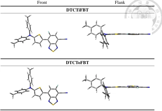
DFT calculations of optimized geometries for DTCTiFBT and DTCToFBT are illustrated in Figure 2-3. The dihedral angles between thiophene (T) and benzothiodiazole (BT) units are 3.5o for DTCTiFBT, 4.2o for DTCToFBT, and 7.0o for DTCTB. The coplanarity of these molecules is presumably due to van der Waals (vdW) forces between the inward hydrogen atom on BT unit and the sulfur atom on T unit, as well as between the inward nitrogen atom on BT unit and the outward hydrogen atom on T unit. The coplanarity of DTCTiFBT is more strengthened due to the substitution of inward electron-deficient fluorine atom, and thus the stronger interaction with the electron-rich sulfur atom. The speculation was confirmed by calculating the distance between the atoms fore-mentioned via space-filling model, which reveals contact between those atoms mentioned. Such coplanarity enhances effective conjugation length and facilitates the intramolecular charge transfer from the electron donating group to the electron withdrawing group, resulting in bathochromic shift and high extinction coefficient. The coplanarity also provides benign intermolecular – interaction, which is beneficial for close packing in solid film.
Front Flank DTCTiFBT
DTCToFBT
Figure 2-3. DFT-optimized geometries for DTCTiFBT and DTCToFBT.
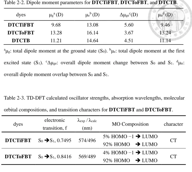
The dipole moments of DTCTiFBT, DTCToFBT, and DTCTB are summarized in Table 2-2. The dipole moment for all six dyes in this thesis point from electron donating amines toward electron withdrawing BT and cyano groups. As compared to DTCTB, DTCTiFBT shows a smaller dipole moment at the ground state, which is cancelled out by the inward direction of the fluorine atom. However, the outward fluorine atom on DTCToFBT lines same direction with the molecular dipole moment, resulting in an increment. At the first excited state (S1), because of further charge separation caused by charge transfer, all molecules show larger dipole moment in same trend, giving a positive Δμge. For the overall dipole moment overlap between S0
and S1, since μgand μe point to nearly the same direction, μtr is very close to μg for each molecule. We anticipate that a higher μe is beneficial for charge separation and thus the incident photo-to-light conversion efficiency.
Table 2-2. Dipole moment parameters for DTCTiFBT, DTCToFBT, and DTCTB.
dyes μga(D) μeb(D) Δμgec(D) μtrd(D)
DTCTiFBT 9.68 13.08 5.60 9.46
DTCToFBT 13.28 16.14 3.67 13.24
DTCTB 11.21 14.64 4.51 11.14
aμg: total dipole moment at the ground state (S0). bμe: total dipole moment at the first excited state (S1). cΔμge: overall dipole moment change between S0 and S1. dμtr: overall dipole moment overlap between S0 and S1.
Table 2-3. TD-DFT calculated oscillator strengths, absorption wavelengths, molecular orbital compositions, and transition characters for DTCTiFBT and DTCToFBT.
dyes electronic transition, f
λexp /λcalc
(nm) MO Composition character DTCTiFBT S0 S1, 0.7495 574/496 5% HOMO −1 LUMO
92% HOMO LUMO CT DTCToFBT S0 S1, 0.8416 569/489 4% HOMO −1 LUMO
92% HOMO LUMO CT
Since the fact that (1) the charge transfer intensity of DTCTiFBT and DTCToFBT are higher than –* band in intensity theoretically and experimentally,
and (2) the main transition of both molecules are from HOMO to LUMO (Table 2-3), we selectively reported isodensity surface plots of the HOMOs and LUMOs of both molecules. As shown in Figure 2-4, the HOMOs of the molecules are mainly populated at ditolylamine and thiophene fragments, whereas the LUMOs are mainly localized at benzothiadiazole and cyano units. The benign separation between HOMO and LUMO facilitates charge transfer absorption, which is beneficial for utilizing the most intense solar irradiance region.
DTCTiFBT DTCToFBT
Figure 2-4. Isodensity surface plots of the HOMO (green) and LUMO (red) of DTCTiFBT and DTCToFBT.
2-5 Crystal Structures and Packings
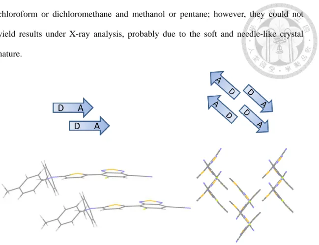
The crystal of DTCTiFBT was obtained via biphasic diffusion between dichloromethane and methanol for X-ray analysis, and its crystal packing is illustrated in Figure 2-5. DTCTiFBT packs in parallel fashion in dimer with an average distance in the range of 3.34–3.45 Å , indicating benign intermolecular −interactions.
However, the dimer lines in same direction with head to head orientation, thus creating net dipole moment. The uncancelled dipolarity could be involved in controlling charge transfer pathways, resulting in energetic disorder in OSCs.27 In crystal packing, DTCTiFBT exhibits nearly perpendicular arrangement between neighboring molecules (the ditolylamine moiety was omitted for clarity.) Though no obvious conduction channel for charge carrier is found, the dipoles cancel in larger domain as illustrated. Moreover, a higher FF of 0.60 was reached for DTCTiFBT/C60 OPV device, suggesting better morphologies in blending layer.
The dihedral angle between T and BT unit is 7.4o for DTCTiFBT, which is less than 7.7o for DTCTB.26 Such observation is similar to the theoretical calculation in Section 2-4.
The crystals of DTCToFBT were obtained via biphasic diffusion between
chloroform or dichloromethane and methanol or pentane; however, they could not yield results under X-ray analysis, probably due to the soft and needle-like crystal nature.
Figure 2-5. Crystal structures of DTCTiFBT in molecular packing.
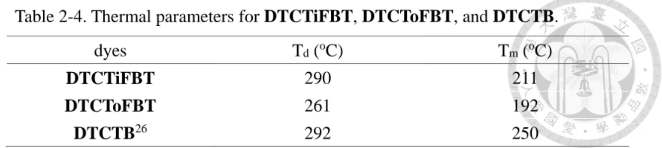
2-6 Thermal Properties
Thermal stabilities and morphological properties of DTCTiFBT and DTCToFBT were investigated by thermogravimetric analysis (TGA) and differential scanning calorimetry (DSC), respectively. Their corresponding data are shown in Fig.
SB1 – Fig. SB4. The decomposition temperatures (Td) (referring to 5% weight loss) are 261–292 oC for these molecules. Thermal stability of materials is crucial for device fabrication under vacuum deposition. Although DTCToFBT shows lowest Td
and Tm among six molecules characterized in this thesis, it maintained the quality of vacuum deposited films and afforded efficient OPVs. To sum up, our D-A-A type molecular configuration could provide benign thermal stability for vacuum fabrication.
Table 2-4. Thermal parameters for DTCTiFBT, DTCToFBT, and DTCTB.
dyes Td (oC) Tm (oC)
DTCTiFBT 290 211
DTCToFBT 261 192
DTCTB26 292 250
2-7 Photovoltaic and Electrochemical Impedance Characteristics
All molecules were subject to vacuum deposition with the OPV structure: ITO / MoO3 (20 nm) / dye: C60 (x nm) / C60 (y nm) / bathocuproine (BCP) (7 nm) / Al (100 nm). MoO3 and BCP were employed as a hole transporting layer and an electron transporting layer, respectively. The active layers comprised of D:A blend films and a thin neat electron acceptor film. The optimized device of DTCTB was repeated to eliminate factors of different time and cooperative partners from Dr. Hao-Chun Ting’s result. The photovoltaic and electrochemical impedance characteristics were measured under simulated AM 1.5 G (100 mW cm-2) illumination. The ratio of dye: C60 was varied from 1:1.6 to 1:2.6 via altering evaporation rate (Å /s) of dyes and C60, and the total thickness of active layers (dye: C60 / C60) were varied from 60 nm to 90 nm, in search of best parameters for device performance. The optimized conditions and device performances are summarized in Table 2-5, and their current density-voltage (J-V) curves along with external quantum efficiency (EQE) spectra are shown in Figure 2-6. It is reasonable that the dye: C60 ratio is 1:2.2 for all thiophene-based devices. Since we only did little change to each molecular backbone, the best mixing ratio along with the morphology in each D:A blend film are similar. Among all, DTCToFBT/C60 OPV cell exhibited a Voc of 0.83 V, a Jsc of 6.85 mA/cm2, and a FF of 0.58, achieving a PCE of 3.28%, which outperformed counterpart DTCTiFBT and non-fluorinated DTCTB. Besides, DTCTiFBT/C60 OPV cell exhibited a Voc of 0.82 V, a Jsc of 6.33 mA/cm2, and a higher FF of 0.60, achieving a PCE of 3.11%, which
still outperformed DTCTB. The lowered HOMO energy levels for DTCTiFBT and DTCToFBT account for the higher Voc, and the bathochromic absorption resulted in the higher Jsc. As for EQE analyses, responses centered at 380–410 nm are contributed mainly by C60 were 55.8%, 52.6%, and 29.0% for DTCTiFBT, DTCToFBT, and DTCTB, respectively; responses centered at 585–598 nm mainly from dyes are 35.2%, 40.9%, and 30.9%, respectively. The former EQE response is stronger than the latter response for DTCTiFBT and DTCToFBT, due to the higher mixing ratio of C60. We anticipate that raising the ratio of an electron donor will improve the 500–700 nm light utilizing efficiency. Further ratio and morphology control in D:A blend film are essential to enhance the performance of each electron donor in this chapter.
Table 2-5. Photovoltaic parameters for DTCTiFBT, DTCToFBT, and DTCTB with OPV structure: ITO / MoO3 / dye: C60 (x nm) / C60 (y nm) / BCP / Al.
dyes dye:
C60
x, y (nm)
Voc
(V)
Jsc
(mA/cm2) FF PCE (%)
Rsh (kΩ cm2)
Rs (Ω cm2) DTCTiFBT 1:2.2 70, 0 0.82 6.33 0.60 3.11 0.73 8.32 DTCToFBT 1:2.2 80, 0 0.83 6.85 0.58 3.28 0.75 11.74
DTCTB 1:2.2 60, 10 0.76 4.88 0.52 1.92 0.51 23.94
(a) (b)
-0.5 0.0 0.5 1.0 1.5
-8 -6 -4 -2 0
DTCTiFBT DTCToFBT DTCTB
Current Density (mA/cm2 )
Voltage (V)
Figure 2-6. (a) J-V curves and (b) EQE spectra for DTCTiFBT (triangles), DTCToFBT (diamonds), and DTCTB (pentagons) for C60-based OPV.
400 500 600 700 800
0 10 20 30 40 50
60 DTCTiFBT
DTCToFBT DTCTB
EQE (%)
Wavelength (nm)
Chapter 3 DTCPiFBT and DTCPoFBT
3-1 Syntheses
The synthetic route of DTCPiFBT and DTCPoFBT is illustrated in Scheme 3-1.
The procedure was similar to that of thiophene-based electron donors reported in Chapter 2, except that 4-(N,N-ditolylamino)-1-(tri-n-butylstannyl)phenylene (dtap-tin) was used as starting material. Stille coupling of dtap-tin and FBTCN directly afforded DTCPiFBT in 81% yield. Stille coupling of dtap-tin and FBTBr afforded DTPoFBTBr in 73% yield, which subsequently underwent Palladium-catalyzed cyanation to give DTCPoFBT in 76% yield.
Scheme 3-1. Synthetic route for DTCPiFBT and DTCPoFBT.
3-2 Optical Properties
Optical properties of DTCPiFBT and DTCPoFBT are shown in Figure 3-1.
Photophysical and electrochemical properties of their and DTCPB are summarized in Table 3-1. In solution state, these molecules perform two bands absorption located at 300–350 nm and 400–600 nm. It is noteworthy that the extinction coefficient of the former band is larger than that of the latter band, which was also found for DTCPB.
Both DTCPiFBT and DTCPoFBT show slightly bathochromic shifts in absorption compared to DTCPB due to the introduction of a fluorine atom. In thin films, all molecules exhibit bathochromic shifts (19–23 nm) in their absorption maxima in the same trend as in solution state. However, all together, the phenylene-bridged electron donors exhibit 63–71 nm hypsochromic shifts as compared to thiophene-bridged counterparts because of the higher aromaticity of phenylene.6-7
(a) (b)
300 400 500 600 700
0 5000 10000 15000 20000 25000 30000 35000
DTCPiFBT DTCPoFBT
Extinction Coefficient (M-1 cm-1 )
Wavelength (nm)
Figure 3-1. Absorption spectra of DTCPiFBT (square) and DTCPoFBT (circle) in (a) CH2Cl2 solutions and (b) vacuum deposited thin films.
Table 3-1. Photophysical and electrochemical parameters for DTCPiFBT, DTCPoFBT, and DTCPB.
dyes λmax soln (nm) (ε, M-1 cm-1)
λmax film (nm)
HOMOa (CV)(eV)
LUMOa (CV)(eV)
EgCV
(eV) IPb (eV) DTCPiFBT 496 (12300)
316 (32700) 515 -5.58 -3.59 1.99 5.56 DTCPoFBT 498 (18300)
320 (33200) 521 -5.67 -3.63 2.04 5.62 DTCPB26 491 (18200) 511 -5.56 -3.52 2.04 5.51
a HOMO (eV) = e [-5.1 - (Eox - EFc/Fc+) ] & LUMO (eV) = e [-5.1 - (Ered - EFc/Fc+) ]. b Determined by photoelectron spectrometer AC-2.
300 400 500 600 700
0.0 0.2 0.4 0.6 0.8
1.0 DTCPiFBT
DTCPoFBT
Normalized Absorbance
Wavelength (nm)
3-3 Electrochemical Properties
Cyclic voltammograms of DTCPiFBT and DTCPoFBT are shown in Figure 3-2.
As shown in Table 3-1, both molecules perform lowered HOMO and LUMO as compared to DTCPB in both solution state and vacuum deposited thin films.
Furthermore, DTCPiFBT shows narrowed bandgap, resulting from the much lowered LUMO energy level. DTCPoFBT exhibits same bandgap as DTCPB; however, the decrement of HOMO and LUMO energy levels are the highest among all newly synthesized electron donors in this thesis. The outward FBT linked to another cyano group could account for stronger electron withdrawing ability and thus stronger propensity for lowering HOMO and LUMO. Such propensity suggests that a higher Voc can be achieved for DTCPoFBT.
1.0 0.5 0.0 -0.5 -1.0 -1.5 -2.0
DTCPoFBT DTCPiFBT
Current (A)
Potential (V vs Fc+/Fc)
Figure 3-2. Cyclic voltammograms of DTCPiFBT and DTCPoFBT.
3-4 Theoretical Calculations
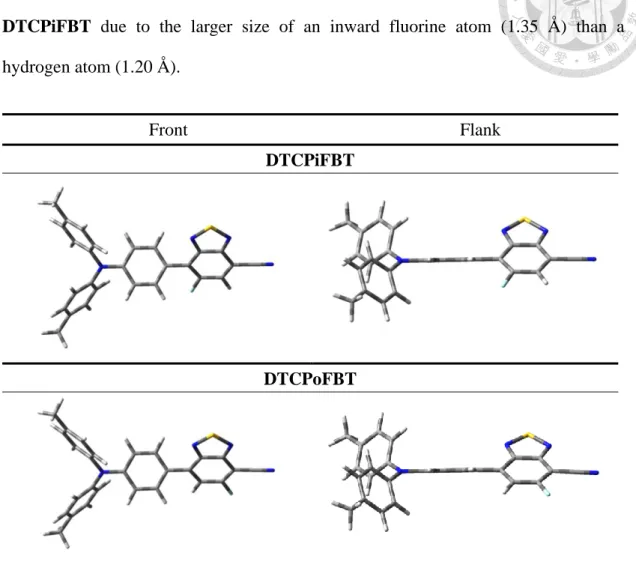
DFT and TD-DFT calculations were performed for DTCPiFBT and DTCPoFBT in CH2Cl2. The optimized geometries for both molecules are showed in Table 3-3. Unlike thiophene-based electron donors mentioned in Chapter 2, all phenylene-based electron donors exhibit highly twisted conformation. The dihedral angles between phenylene (P) and benzothiodiazole (BT) units are 40.9o for
DTCPiFBT, 35.0o for DTCPoFBT, and 36.1o for DTCPB. The non-copolanirity is due to ortho–ortho steric interaction between P and BT units, which is greater for DTCPiFBT due to the larger size of an inward fluorine atom (1.35 Å ) than a hydrogen atom (1.20 Å ).
Front Flank
DTCPiFBT
DTCPoFBT
Figure 3-3. DFT-optimized geometries for DTCPiFBT and DTCPoFBT.
The dipole moments of DTCPiFBT, DTCPoFBT, and DTCPB are summarized in Table 3-2. The total dipole moments for all molecules are smaller as compared to the counterparts of thiophene-based molecules. Also, inward fluorination gives smaller dipole moment in both S0 and S1, whereas outward fluorination gives larger dipole moment than non-fluorinated DTCPB. At the first excited state, because of charge separation caused by charge transfer, all molecules show larger dipole moment in same trend.
Table 3-2. Dipole moment parameters for DTCPiFBT, DTCTPoFBT, and DTCPB.
dyes μga(D) μeb(D) Δμgec(D) μtrd(D)
DTCPiFBT 8.05 10.62 2.58 8.04
DTCPoFBT 11.10 13.84 2.76 11.10
DTCPB 9.36 12.29 2.96 9.36
aμg: total dipole moment at the ground state (S0). bμe: total dipole moment at the first excited state (S1). cΔμge: overall dipole moment change between S0 and S1. dμtr: overall dipole moment overlap between S0 and S1.
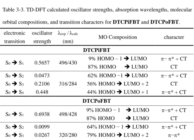
The absorption located at 400–600 nm corresponds mainly to transition from S0
to S1, which is prominently constituted by the charge transfer excitation from HOMO to LUMO. However, the main absorption spanning 300–350 nm comprises several electronic transitions, which sums to larger oscillator strength. Such observation could be correlated to the twisted conformation phenylene-based molecules possess.
Table 3-3. TD-DFT calculated oscillator strengths, absorption wavelengths, molecular orbital compositions, and transition characters for DTCPiFBT and DTCPoFBT.
electronic transition
oscillator strength
λexp /λcalc
(nm) MO Composition character
DTCPiFBT
S0 S1 0.5657 496/430 9% HOMO – 1 LUMO 87% HOMO LUMO
−* + CT CT S0 S2
S0 S3
S0 S4
0.0473 0.2106 0.448
316/284
62% HOMO −1 LUMO 56% HOMO LUMO + 2 44% HOMO LUMO + 1
−* + CT CT
−* + CT DTCPoFBT
S0 S1 0.6938 498/428 9% HOMO − 1 LUMO 87% HOMO LUMO
−* + CT CT S0 S2
S0 S3
S0 S4
0.0099 0.0267 0.5630
320/280
64% HOMO − 1 LUMO 79% HOMO LUMO + 2 64% HOMO LUMO + 1
−* + CT
−*
−* + CT
Though both molecules possess several electronic transitions, the most significant transition is from HOMO to LUMO via charge transfer. As shown in Figure 3-4, the benign separation between HOMO and LUMO is similar with thiophene-based molecules.
DTCPiFBT DTCPoFBT
Figure 3-4. Isodensity surface plots of the HOMO (green) and LUMO (red) of DTCPiFBT and DTCPoFBT.
3-5 Crystal Structures and Packings
The crystals of DTCPiFBT and DTCPoFBT were easily obtained by slow evaporation of dichloromethane. Their crystal packings are illustrated in Figure 3-5.
DTCPiFBT shows antiparallel fashion in dimer with an average distance in the range of 3.64–3.70 Å , indicating benign intermolecular −interactions (the residue solvent was omitted for clarity.) However, no obvious packing pattern in crystal grain was found. Unlike the antiparallel fashion for DTCPiFBT and DTCPB, the crystal of DTCPoFBT exhibits zig-zag orientation both in dimer and in crystal packing. Such observation is presumably correlated to vdW interaction between a fluorine atom and two hydrogen atoms on P unit, which was only found in DTCPoFBT. As a result, the distance between each dimer ranges 3.30–3.57 Å . Introduction of a fluorine atom can
provide more interaction in crystal packing concomitant with morphology alteration for the active layer in BHJ device.
The ortho–ortho steric interaction between P and BT induces the dihedral angles more than 27o (34.8o for DTCPiFBT, 29.7o for DTCPoFBT, and 27.3o for DTCPB26). The larger dihedral angle of DTCPiFBT is due to the steric hindrance from the inward fluorine atom. The observation is similar to the results in Section 3-4.
DTCPiFBT DTCPoFBT
Figure 3-5. Crystal structures of DTCPiFBT and DTCPoFBT in molecular packing.
3-6 Thermal Properties
Thermal stabilities and morphological properties of DTCPiFBT and DTCPoFBT are shown in Fig. SB5 – Fig. SB8 and summarized in Table 3-4. The decomposition temperatures are above 270 oC for all molecules, which are suitable for vacuum fabrication. However, no distinct correlation for fluorination and the change in Td and Tm was found.
Table 3-4. Thermal parameters for DTCPiFBT, DTCPoFBT, and DTCPB.
dyes Td (oC) Tm (oC)
DTCPiFBT 209
DTCPoFBT 191
DTCPB26 204
3-7 Photovoltaic and Electrochemical Impedance Characteristics
DTCPiFBT and DTCPoFBT were subject to vacuum deposition with the OPV structure: ITO / MoO3 (20 nm) / dye: C60 (x nm) / BCP (7 nm) / Al (100 nm). The photovoltaic and electrochemical impedance characteristics were measured under simulated AM 1.5 G (100 mW cm-2) illumination. The device performances are summarized in Table 3-5, and their J-V curves along with EQE spectra are shown in Figure 3-6. DTCPoFBT/C60 OPV cell exhibited a Voc of 0.88 V, a Jsc of 6.50 mA/cm2, and a high FF of 0.63, achieving a PCE of 3.62%. DTCPiFBT/C60 OPV cell exhibited a Voc of 0.89 V, a Jsc of 4.90 mA/cm2, and a FF of 0.58, achieving a PCE of 2.65%. As for EQE analyses, responses centered at 380–400 nm contributed mainly by C60 were 53.9% and 54.5% for DTCPiFBT and DTCPoFBT, respectively; responses centered at 530–535 nm mainly from dyes were 32.1%, and 42.7%, respectively. The former band is similar in intensity, whereas the latter band shows significant difference, as expected. Due to the highly twisted backbone of DTCPiFBT, its CT harvesting efficiency is lower than that of DTCPoFBT, resulting in inferior EQE response.
In summary, the tendency in Voc of the new OPV devices in this thesis was coincident with the HOMO levels determined from cyclic voltammogram or AC-2.
The low-lying HOMO level of DTCPoFBT resulted in a high Voc of 0.88 V. However, the Jsc of DTCPoFBT was lower than that of DTCToFBT (6.85 mA/cm2) due to the larger bandgap of phenylene-based electron donors. The results demonstrated a trade-off between Voc and Jsc for a series of D-A-A based devices. Among all,
DTCPoFBT stroke a balance between the photovoltage and the photocurrent, achieving a remarkable PCE of 3.62%.
dyes dye:
C60
x (nm)
Voc
(V)
Jsc
(mA/cm2) FF PCE (%)
Rsh (kΩ cm2)
Rs (Ω cm2) DTCPiFBT 1:1.4 70 0.89 4.90 0.58 2.65 1.11 24.01 DTCPoFBT 1:1.8 70 0.88 6.50 0.63 3.62 1.28 17.19 Table 3-5. Photovoltaic parameters for DTCPiFBT and DTCPoFBT with OPV structure: ITO / MoO3 / dye: C60 (x nm) / BCP / Al.
(a) (b)
-0.5 0.0 0.5 1.0 1.5
-8 -6 -4 -2 0
DTCPiFBT DTCPoFBT
Current Density (mA/cm2 )
Voltage (V)
Figure 3-6. (a) J-V curves and (b) EQE spectra for DTCPiFBT (square), and DTCPoFBT (circle) for C60-based OPV.
Encouraged by the promising results, we decide to replace the electron acceptor in pursuit of better device performance. C70 is adopted to replace C60 because of its broader optical absorption and higher extinction coefficient, which can provide better light-harvesting capabilities.28 Besides, we expect a much higher Voc can be reached for DTCPoFBT as optimizing conditions, which will improve morphology and reduce charge recombination. Further investigation of all newly synthesized electron donors in this thesis is in process.
400 500 600 700 800
0 10 20 30 40 50 60
DTCPiFBT DTCPoFBT
EQE (%)
Wavelength (nm)
Conclusions
Our work characterized the effect of F-substituted benzothiadiazole unit on D-A-A structured small molecule electron donors. Though DTCTiFBT and DTCToFBT as well as DTCPiFBT and DTCPoFBT have regioisomeric nature, introduction of an inward or outward fluorine atom can alter dihedral angles and crystal packings by providing additional interactions or steric hindrance. All molecules show lowered HOMO and LUMO level and slightly red-shifted absorption as compared to those of the non-fluorinated counterparts, which are beneficial for pursuing higher Voc and Jsc, respectively. Furthermore, all molecules possess benign thermal stability, high extinction coefficient, and appropriate energy levels suitable for OPV application. Among all, thiophene-bridged DTCToFBT/C60 OPV cell exhibited a Voc of 0.83 V, a Jsc of 6.85 mA/cm2, and a FF of 0.58, achieving a PCE of 3.28%.
Pheneylene-bridged DTCPoFBT/C60 OPV cell exhibited a Voc of 0.88 V, a Jsc of 6.50 mA/cm2, and a high FF of 0.63, achieving a remarkable PCE of 3.62%. All molecules are subject to further investigation.
Experiment Session
Syntheses and Materials.
All chemicals and reagents were used as received from commercial sources without purification. THF was dried by molecular sieves, and toluene was distilled by P2O5 as the drying agent. 4,7-dibromo-5-fluorobenzo[c][1,2,5]thiadiazole (FBTBr) was synthesized according to previous literature.15
Synthesis of 4-bromo-7-cyano-5-fluorobenzo[c][1,2,5]thiadiazole (FBTCN)
A mixture of FBTBr (6.24 g, 20 mmol), Zn(CN)2 (1.64 g, 14 mmol), and Pd(PPh3)4
(2.31 g, 2 mmol) in anhydrous N-methyl-2-pyrrolidone (NMP) (30 mL) was stirred and heated at 120 oC for 2 h under argon atmosphere. After cooled down to room temperature, the solution was poured to celite with ethyl acetate (EA) as eluent, followed by extraction with EA and brine several times to eliminate NMP. The crude product was purified by column chromatography with dichloromethane/hexane as eluent (v/v, 1:1) to afford FBTCN as a yellow solid (2.03 g, 39%), mp 143-144 oC; IR (KBr) 845, 876, 899, 1191, 1298, 1318, 1326, 1394, 1484, 1593, 1636, 2236, 3448 cm−1; 1H NMR (CDCl3, 400 MHz) δ 7.94 (d, J = 8.0 Hz, 1H); 13C NMR (CDCl3, 100 MHz) δ 159.2 (d, J = 254.5 Hz), 153.5 (d, J = 6.0 Hz), 149.4, 126.6 (d, J = 31.7 Hz), 113.6 (d, J = 2.7 Hz), 105.9 (d, J = 24.1 Hz), 105.1 (d, J = 10.1 Hz); 19F NMR (CDCl3, 376 MHz) δ -102.2 (d, J = 7.9 Hz, 1F); HRMS (m/z, FAB+) Calcd for C7H79BrFN3S 256.9059 found 256.9055, Calcd for C7H81BrFN3S 258.9038 found 258.9037.
Synthesis of DTCTiFBT
A mixture of 4-(N,N-ditolylamino)-1-(tri-n-butylstannyl)thiophene (7 mmol), FBTCN (1716 mg, 6.65 mmol), and PdCl2(PPh3)2 (246 mg, 0.35 mmol) in anhydrous toluene (22 mL) was stirred and heated at 120 oC for 3 h under argon atmosphere. After cooled down to room temperature, the solvent was removed by rotary evaporation.
The crude product was further purified by column chromatography with dichloromethane/hexane as eluent (v/v, 1:2). DTCTiFBT was obtained as a purple solid (2342 mg, 77%), mp 211 oC (DSC); IR (KBr) 1156, 1328, 1360, 1389, 1434, 1507, 2222, 2860, 2921, 3040 cm−1; 1H NMR (CDCl3, 400 MHz) δ 8.25 (d, J = 4 Hz, 1H), 7.85 (d, J = 12 Hz, 1H), 7.14-7.20 (m, 8H), 6.54 (dd, J = 4.5, 1.5 Hz, 1H), 2.36 (s, 6H) ; 13C NMR (CDCl3, 100 MHz) δ 160.5 (d, J = 9.1 Hz), 155.3 (d, J = 252.4 Hz), 151.9 (d, J = 11.1 Hz), 151.0, 144.4, 134.9, 134.0 (d, J = 10.1 Hz), 130.2, 126.9 (d, J
= 33.2 Hz), 124.8, 119.7 (d, J = 7.0 Hz), 119.3 (d, J = 14.1 Hz), 115.0, 114.2, 98.5 (d, J = 12.1 Hz), 21.0; 19F NMR (CDCl3, 376 MHz) δ -112.0 (d, J = 12.4 Hz, 1F) HRMS (m/z, FAB+) Calcd for C25H17FN4S2 456.0879 found 456.0883.
Synthesis of DTToFBTBr
A mixture of 4-(N,N-ditolylamino)-1-(tri-n-butylstannyl)thiophene (1.5 mmol),
FBTBr (468 mg, 1.5 mmol), and PdCl2(PPh3)2 (53 mg, 0.075 mmol) in anhydrous toluene (4.7 mL) was stirred and refluxed overnight under argon atmosphere. After cooled down to room temperature, the solvent was removed by rotary evaporation.
The crude product was further purified by column chromatography with dichloromethane/hexane as eluent (v/v, 1:4). DTToFBTBr was obtained as a black solid (510 mg, 67%), mp 178-180 oC; IR (KBr) 813, 1291, 1454, 1511, 1593, 1667, 2864, 2913, 3023 cm−1; 1H NMR (CDCl3, 400 MHz) δ 7.98 (d, J = 4 Hz, 1H), 7.42 (d, J = 12 Hz, 1H), 7.11-7.16 (m, 8H), 6.54 (d, J = 4 Hz, 1H), 2.35 (s, 6H); 13C NMR (CDCl3, 100 MHz) δ 160.9 (d, J = 251.4 Hz), 156.7, 154.3, 149.0, 144.8, 134.2, 130.1, 129.5, 128.0 (d, J = 11.1 Hz), 126.7, 124.1, 116.2, 113.7 (d, J = 30.2 Hz), 93.8, 20.9;
19F NMR (CDCl3, 376 MHz) δ -104.3 (d, J = 11.3 Hz, 1F); HRMS (m/z, FAB+) Calcd for C26H1979BrFN3S 509.0031 found 509.0034, Calcd for C26H1981BrFN3S 511.0011 found 511.0010.
Synthesis of DTCToFBT
A mixture of DTToFBTBr (306 mg, 0.6 mmol), Zn(CN)2 (49 mg, 0.42 mmol), Pd(PPh3)4 (55 mg, 0.048 mmol) in degassed NMP (6 mL) was stirred and heated at 120 oC for 2 h under argon atmosphere. After cooled down to room temperature, the solution was extracted with EA and brine several times to remove NMP. The crude product was purified by column chromatography with dichloromethane/hexane as eluent (v/v, 1:1) to afford DTCToFBT as a purple solid (240 mg, 89%), mp 192 oC (DSC); IR (KBr) 1054, 1156, 1217, 1348, 1442, 1507, 1552, 2227, 2860, 2921, 3032
cm−1; 1H NMR (CDCl3, 400 MHz) δ 8.17 (d, J = 4 Hz, 1H), 7.29 (d, J = 12 Hz, 1H), 7.16-7.21 (m, 8H), 6.48 (d, J = 4 Hz, 1H), 2.37 (s, 6H); 13C NMR (CDCl3, 100 MHz) δ 167.0 (d, J = 264.5 Hz), 160.7, 153.9 (d, J = 8.0 Hz), 148.6, 144.0, 135.5, 133.9 (d, J = 12.1 Hz), 133.2, 130.3, 125.0, 124.1, 114.0, 111.8, 110.3 (d, J = 27.2 Hz), 86.1 (d, J = 19.1 Hz), 21.0; 19F NMR (CDCl3, 376 MHz) δ -99.8 (d, J = 10.5 Hz, 1F); HRMS (m/z, FAB+) Calcd for C25H17FN4S2 456.0879 found 456.0886.
Synthesis of DTCPiFBT
A mixture of 4-(N,N-ditolylamino)-1-(tri-n-butylstannyl)phenylene (9 mmol), FBTCN (2207 mg, 8.55 mmol), and PdCl2(PPh3)2 (316 mg, 0.45 mmol) in anhydrous toluene (28 mL) was stirred and heated at 120 oC for 3 h under argon atmosphere.
After cooled down to room temperature, the solvent was removed by rotary evaporation. The crude product was further purified by column chromatography with dichloromethane/hexane as eluent (v/v, 1:2). DTCPiFBT was obtained as a black solid (3131 mg, 81%), mp 209 oC (DSC); IR (KBr) 817, 1156, 1332, 1487, 1507, 1548, 1601, 2235, 2860, 2921, 3023, 3056 cm−1; 1H NMR (CDCl3, 400 MHz) δ 7.96 (d, J = 10.1 Hz, 1H), 7.69 (dd, J = 8.8, 1.6 Hz, 2H), 7.09-7.14 (m, 10H), 2.34 (s, 6H),
13C NMR (CDCl3, 100 MHz) δ 157.1 (d, J = 251.4 Hz), 153.9 (d, J = 10.1 Hz), 150.8, 149.7, 144.3, 134.0, 131.5 (d, J = 4.0 Hz), 130.2, 127.6 (d, J = 33.2 Hz), 125.8, 124.8 (d, J = 15.1 Hz), 121.0, 119.7, 114.5, 102.7 (d, J = 12.1 Hz), 20.9; 19F NMR (CDCl3, 376 MHz) δ -115.0 (d, J = 10.5 Hz, 1F); HRMS (m/z, FAB+) Calcd for C27H19FN4S 450.1314 found 450.1306.