高性能耐燃複合紗開發研究
A Study on high performance flame-retardant composite yarns
NSC 97-2221-E-011-031 蘇清淵(Ching-Iuan Su) 國立臺灣科技大學 高分子工程系
E-mail: cysu@mail.ntust.edu.tw
ABSTRACT: This study employed a SKF draft system equipped with an additional spreading device to form a high performance flame-retardant composite yarn. For mixing the spread Technora
®filaments and Stretch-Broken oxidized fibers, nip of the front rollers was arranged for best dispersion. The yarn unevenness (CV %), strength, abrasion-resistance, and Limited Oxygen Index (LOI) of the composite yarn were evaluated. The cross-sections of the actual composite yarn were observed to assess its structure and the effect on yarn performance. The experimental results showed that the yarn CV% is worse as the yarn count (Tex) tend to be finer. This would be an optimum condition adopting 30 TM for the yarn evenness and yarn strength. After abrasion test, the residual strength of composite yarns remains above 80%. The LOI value depends on the coverage degree of oxidized fiber outside the yarn surface, and there tended to be a lower LOI value with finer yarn count (Tex). Overall, the T/O composite yarn with uniform distribution structure can provide high performance and flame-retardancy.
.
Keywords: Oxidized Fiber, Technora
®, Composite Yarn, LOI
摘要: 本研究係使用氧化纖維與 Technora
®纖維混合,
以加強其防火材料之機械特性,改善其產業用途。實驗
過程中,以紡製 Technora
®/氧化纖維(T/O)複合紗為目標,使用 SKF 牽伸裝置,將氧化纖維束牽伸拉斷成短纖
維,同時將 Technora
®喂入置於中羅拉入口處上方的靜
電開纖器具,經由上下皮圈引導,在前羅拉出口處的紡 紗三角區域紡成高性能氧化纖維複合紗。實驗中觀察
Technora
®/氧化纖維(T/O)複合紗兩種纖維結合狀態,探討各種變因對複合紗成紗結構之影響。以複合紗 CV%、
強力、耐磨性、以及限氧指數之測試,進行複合紗性能 評估。實驗結果顯示,斷面型態會影響其紗線性能。但 整體而言,CV%隨著紡製支數提升而上升,強力隨著撚 度提高有上升趨勢,但當撚係數超過 35(Tex 制)時達到 臨界值後開始下降。殘餘強度能維持 80%水平之上,在 限氧指數方面也有不錯水準。綜合言之,具有均勻結構
之 Technora
®/氧化纖維複合紗,兼具有較佳的機械特性與良好的防火性能。
關鍵詞: 氧化纖維、Technora
®、複合紗、限氧指數
INTRODUCTION
Polyacrylonitrile (PAN) oxidized fibers have good thermal stability at temperatures up to 900℃. These fibers do not burn or melt in air, will not produce toxic gas, and resist acids and bases. Thus they can be used in various flame-retardant applications, such as clothing, upholstery and thermal insulation for buildings. Oxidized fibers mixed with aromatic fibers to form a composite yarn will reinforce mechanical properties for the end uses. Such as aircraft seats, upholstery, industrial liners uses, as well as
protective clothing for fire fighters, soldiers, police, and steel workers. Therefore, oxidized fibers are becoming increasingly important and widely used.
In this work, the PAN-based oxidized tow was mixed with Technora® to reinforce the mechanical properties for end use by combining the direct spinning method with the static spreading method. In the experiment, PAN-based oxidized tow was stretch-broken into staple fibers in direct spinning. The direct spinning method simplifies the process of conversion even further by going directly from tow to spun yarn in a single stretch-breaking, drafting, and twisting operation. It is different from the conventional spun yarn spinning for staple fibers [1~5]. The high performance multifilament (Technora®) was passed through a spreading electrode [6] and blended with oxidized fibers behind the front roller, thus spinning a Technora® filament/ oxidized fiber composite yarn (T/O composite yarn)[7~9]. This enhances strength and abrasion resistance of the high performance flame-retardant composite yarn for industrial use.
THEORETICAL BACKGROUND
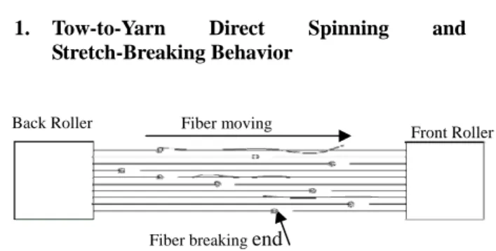
1. Tow-to-Yarn Direct Spinning and Stretch-Breaking Behavior
Back Roller
Front Roller
The process of tow-to-yarn direct spinning uses two pairs of rollers for a stretch-break system. The tow is fed into the back roller, and sent out the front roller with higher rotation speed, during which each piece of fiber is broken at the weakest point because of the speed difference in the rollers, As a result, stretch-breaking occurs to the tow between rollers. Following this, the tow is sent with the twist caused by the traveler sliding around the ring which surrounds the bobbin, and spun into oxidized fiber yarn in the triangular zone at the outlet of the front roller. Figure 1 shows that during the stretch-break, the breaking point of the fiber tow is stochastic, so the fiber leading end will change its position with the rotation speed of the roller, and the length of broken fiber will be out of control. In other words, longer fibers will be produced if the breaking point is closer to the back roller, and shorter fibers will be produced if the breaking point is near the front roller [2].
Figure 1 Fiber breaking ends during
Fiber breaking
end
Fiber moving
2. Type of Twisting
As early as 1928, Balls [10] discussed two types of twisting, ribbon twisting is formed under low tension, whereas cylindrical twisting takes places at high tension.
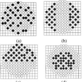
Bose [10] (1963) showed that the twisted form is preferred for low twists, but that the wrapped form becomes preferable at higher twists, and there is an intermediate region in which both forms exist together. Thus, three possible ways of yarn twisting were considered: (1) twisted cylindrical form, (2) twisted ribbon form, and (3) wrapped ribbon form. These forms are illustrated schematically in Figure 2.
(a) (b) (c)
Figure 2 Three types of yarn twisting [4]
(a) cylindrical twisting, (b) twisted ribbon form,
(c) wrapped ribbon form
3. Twisting of A Model Assembly
(a) static twisting (b) continuous twisting
Figure 3 Filament arrangements during twisting of two layers [4]
A model assembly of coarse mono-filaments was studied by Hearle and Bose [10] (1966) to see how the different forms appear in twisted fibrous structures. At a higher level of twist (3.5 tpi), as shown in Figure 3b, continuous twisting of two layers fed through a slot gave a twisted ribbon form, followed by an N-shaped structure, the buckling was irregular and a multilayer structure appeared.
However, the final structure was cylindrically close-packed, with most of one color of threads on the surface and most of the others in the core.
EXPERIMENTS
The 1536Tex/12k PAN-based oxidized tow from the Formosa Plastics Corporation of Taiwan was fed through the back roller of a two drafting-three pairs of rollers with an apron draft system. In the spinning frame, the oxidized
tow was first stretch-broken to form a sliver in the break draft zone, and then was directly drafted by the apron system in the main draft zone. 222dTex/133f Technora
®multifilament was positioned on an additional rack. The Technora
®multifilament was passed through a spreading electrode and blended with the oxidized fiber behind the front roller, thus spinning a Technora
®filament/Oxidized staple fiber (T/O) composite yarn. As shown in Figure 4, a laboratory spinning frame with SKF drafting system is equipped with a set of special spreading apparatus [5]. The T/O composite yarn unevenness (CV%) was tested on an Keisokii Evenness Tester, the breaking strength was tested on an Orientec Tensilon, RTA-1T, the abrasion resistance was tested on a Zweigle G550 abrasion tester, the LOI was measured on Stanton Reddcroft according to ASTM D2863 [11], and the cross sections of T/O composite yarn were examined by Cambridge SEM S360.
Figure 4 Diagram for composite yarn spinning [5]
Four artificial cross-section models [7] were used to classify the T/O composite yarn, as shown in Figure 5. The classifications were the (1) uniform distribution model, (2) asymmetrically sided model, (3) segregated model, and (4) core type model. One hundred cross-sections of the actual T/O composite yarn were chosen randomly and classified as shown in Figure 6.
(1) Uniform distribution type : a cross section structure of the composite yarn in which Technora
®filaments are spread evenly dispersed in the cross section, as shown in Figure 6(a).
(2) Asymmetrically sided type : a cross section structure of the composite yarn in which spread Technora
®filaments are distributed on two sides, as shown in Figure 6(b).
(3) Segregated type:a cross section structure of the composite yarn in which spread Technora
®filaments are gathered aside, as shown in Figure 6(c).
(4) Core type:a similar cross section structure of the
core yarn in which Technora
®filaments are
(7) Top roller pressure (kgf): 28 gathered in the inner region of cross section, as
shown in Figure 6(d). (8) Twist Multiplier (TM, in Tex system): 25, 30, 35, and 40
(9) Spindle speed (rpm): 3500
(10) T/O composite yarn count (Tex): 48, 37, and 30
All the work of the T/O composited yarn properties were carried out at 20 ± 2℃ and 65 ± 5 % RH.
RESULTS AND DISCUSSION
1. Effect of twist multiplier on cross-section structure of composite yarn
(a)
(b)
Table 1 Effect of twist multiplier on the cross section structure
Twist multiplier, TM Cross section type (%)
25 30 35 40 Uniform distribution 25 22 18 18 Asymmetrically sided 26 27 28 27
Segregated 19 23 22 28
Core 30 28 32 27
(c) (d)
Figure 5 Artificial cross-section models of composite yarns Note: in case of 48Tex composite yarn (a)Uniform distribution model, (b) Asymmetrically
sided model,(c) Segregated model, (d) Core model. In the spinning triangle area, when twist multiplier (TM) increased, both the tangential and radial forces of interfiber increased. The external force acted on the yarn will produce the lateral pressure on fibers in the inside layer, resulting in the gathering of spread filaments. Consequently, it directly influences the cross-section structure of the T/O composite yarn. Generally, the TM of oxidized yarn is about 45. During spinning of the T/O composite yarn, reducing TM both maintains yarn strength and also increases the production rate. Therefore, the value range of 25∼40 for TM was chosen for the experiment to study its effect on the cross-section structure. Table 1 shows the change of the fraction amount of the cross-section of uniform distribution type from 25.0% down to 18.0%, corresponding to 48Tex composite yarn when TM increases from 25 to 40.
Figure 6 Cross-sections of the composite yarn (a) Uniform distribution type (b) Asymmetrically sided type, (c) Segregated type, (d) Core type.
The four types of cross section were studied and the experimental results were statistically analysed. The spinning conditions were:
(1) Oxidized tow (Tex): 1536 /12k
(2) SKF system: two drafting-three pairs of rollers with apron draft system
(3) Break draft ratio: 14 (4) Back roller gauge (mm): 90 (5) Total draft ratio: 34, 42, and 51 (6) Top roller hardness (
o): 75
2. CV% of the T/O composited yarn
For actual spinning, we varied the draft ratio to investigate the effect of spinning conditions on the unevenness (CV %) of oxidized direct spun yarn. As Figure 7 shows, to change the TM had no effect on the CV% of yarn. However, as the draft ratio increased, the yarn CV% appears to increase.
For example, in the case of the TM 30, the yarn CV%
tended to increase from 7.5% to 9.5% when the draft ratio setting changed from 34(48Tex) to 42(37Tex).
Consequently, too much increase in the draft ratio, that is, spinning a finer yarn, makes the stretch-breaking behavior out of control, reducing yarn quality. This is mainly because changing the draft ratio changes the amount of oxidized fiber in the T/O composite yarn. Calculations show that when draft ratio is 34(48Tex), 42(37Tex), and 51(30Tex), the number of fibers is 353, 386, and 235, respectively. The other component, Technora
®multifilament did not go through the stretch-breaking procedure and was used with the original fiber number and denier. Its CV% is always about 6.0. The presence of Technora
®is responsible for the lower CV% of T/O composite yarn. This is especially clear when there is less oxidized fiber.
(c) (d)
(a) (b)
Figure 7 Relationship between yarn CV% and TM corresponding to three kinds of yarn Tex
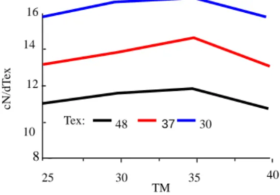
3. Composite yarn strength
There is a certain minimum value of TM, below which it is impossible to spin a spun yarn. Above this minimum TM, which is strongly influenced by staple length, fineness, and fiber surface (frictional) characteristics, the cohesiveness (yarn strength) between fibers initially increases at a fairly rapid rate. At low TMs, the initial increase in yarn strength is determined by the resistance of fibers to slippage. At high TMs, the contribution because of resistance to slippage reaches a steady maximum. However, as the TM becomes high, the effect of fiber obliquity comes into play, and this tends to reduce yarn strength. The twist-strength relationship is therefore the result of the simultaneous operation of the two effects discussed above.
Figure 8 shows the yarn strength increased from 16.04cN/dTex to 16.69cN/dTex, corresponding to 30Tex composite yarn as TM increased from 25 to 35. This is because an increase in the twist multiplier increased interfiber cohesion between filaments and staple fibers.
Then, the yarn strength declined to 15.45cN/dTex as the TM increases up to 40 because of the effect of fiber obliquity. When processed in 37Tex and 48Tex yarns, the effect of TM on the yarn strength followed the same trend.
Figure 8 Relationship between yarn strength and TM corresponding to three kinds of yarn Tex
4. Residual strength
In the experiment, the composite yarn was rubbed against
#500 sandpaper (Switzerland) on a Zweigle G550 abrasion tester to evaluate the abrasion resistance of the composite yarn. After being rubbed 40 times, we measured its strength of the rubbed yarn. The percentage of residual
strength (PRS %) of the T/O composite yarn was calculated by the formula: PRS% = [(original yarn strength - rubbed yarn strength) / original yarn strength]*100%. As shown in Table 2, the percentage of residual strength (PRS
%) retained by the T/O composite yarn was up to 80%.
This indicates that the T/O composite yarn had very good abrasion resistance, and is suitable for industrial use.
14
Table 2 Residual strength (PRS %) of the T/O composite yarns
The appearance of the composite yarn after abrasion test was examined. We found that the outer oxidized fibers had been stripped and separated from the yarn body, especially in the case of the Core type T/O composite yarn. In addition, the uniform distribution type was not so obvious because the Technora
®filaments are evenly dispersed in the cross section, resulting the fine mixing between Technora
®filaments and oxidized fibers. This reduced the stripping phenomenon and improved the yarn quality.
5. LOI
The LOI values of 60~62 for the oxidized fiber and 29~32 for the Technora
®used in this experiment differ greatly.
The LOI test showed that the flame attacked the bare Technora
®fibers outside the yarn surface and continued to spread all around. The flame will be extinguished by the retardant effect of the oxidized fibers. So if the two fibers are blended, when Technora
®fiber of lower LOI value is covered by oxidized fiber of high LOI value, this will help raise the LOI value of the T/O composite yarn.
Figure 9 clearly shows that the order of LOI value for these three yarn counts is: 48Tex> 37Tex> 30Tex. This is because the oxidized fiber content of 48Tex yarn is higher than the other two yarns of 37Tex and 30Tex, and the LOI value depends on coverage degree of oxidized fiber outside the yarn surface. However, the LOI value of all the T/O composite yarn fabrics are over 45 LOI, no matter what TM is used.
Figure 9 Relationship between LOI and TM corresponding to three kinds of yarn Tex
Tex
TM
48 37 30
2.5 91.0 86.0 83.1
3.0 90.8 85.2 82.3
3.5 90.6 84.8 81.5
4.0 90.2 84.4 80.8
20 30 35
12
40 6
8
TM
CV% 10
Tex: 48
37 30
16
25
8
1230 35 40
TM
48 37 30
cN/dTex
10 14
Tex:
37
30
60 Tex: 4840
LOI 20
0
30 35 40
25
TM
![Figure 2 Three types of yarn twisting [4]](https://thumb-ap.123doks.com/thumbv2/9libinfo/9122662.407300/2.892.111.420.294.837/figure-types-yarn-twisting.webp)