A Wide-Speed High Torque Capability utilizing Overmodulation Strategy in DTC of Induction Machines with Constant Switching Frequency Controller
A. Jidin, M.F.M Basar, A. Noordin Department of Power Electronics and Drives
Universiti Teknikal Malaysia Melaka Malacca, Malaysia
auzani@ieee.org
N.R.N Idris, A.H.M. Yatim Department of Energy Conversion
Universiti Teknologi Malaysia Johore, Malaysia nikrumzi@ieee.org
Abstract -- This paper presents a simple overmodulation method employed in Direct Torque Control (DTC)-Constant Switching Frequency (CSF) controller of induction machines.
The proposed overmodulation method is utilized to extend a constant torque region and hence produces high torque capability in field weakening region with six-step operation. It will be shown that the overmodulation operation using the DTC- CSF scheme can be established by controlling the stator flux locus from circular to the hexagonal shape. This is achieved by modifying the flux error status produced from flux hysteresis controller, before it is being fed to the look-up table. The main benefit in the proposed strategy is its simplicity and it can be implemented in many electric drive applications to obtain maximum torque capability for a wider speed range operation.
Index Terms-- Overmodulation, Induction Machine, Field weakening, Direct torque control.
I. INTRODUCTION
The capability of induction machine drives to operate in overmodulation and field weakening modes are very important many applications. It is desirable to operate under these conditions in order to achieve maximum torque capability and to fully utilize the DC link voltage over a wide speed range of operation.
Several papers were published [2]-[6] proposing the solution of achieving maximum torque capability in field weakening region. The common approach adopted is to estimate the optimal flux level of the motor based on the maximum values of inverter voltage and inverter current.
Typically, the algorithms require frame transformer, knowledge of machine parameters and space-vector modulator. For example, [2] used Field Oriented Control- Space Vector Modulation (FOC-SVM) that considers voltage and current limit conditions to compute the controllable currents (in stator flux reference frame) in achieving the appropriate flux level in field weakening region. Besides that, numerous papers had been reported to provide a robust field weakening strategy so that any variations of machine parameters used in calculating the optimal flux can be compensated [3][4].
In general, the SVM technique is employed to exploit the inverter voltage into overmodulation region where the voltage reference is normally used to define the mode of overmodulation [1]. The ability of SVM to fully utilize the
available inverter voltage mainly depends on the vector control strategy to produce the maximum possible voltage reference while simultaneously maintaining the regulation of flux and torque. Various methods were proposed to estimate the voltage reference, for instances in the case of DTC-SVM, [6] utilized predictive control of stator flux error vector to estimate the reference voltage and [7] used dead-beat control with several complicated equations to generate the reference voltage in real-time. Obviously, all these methods [2]-[7]
consequently complicate the basic control structure of DTC drive systems. Among the various schemes proposed, only [5][6] can achieve maximum torque capability in field weakening region with six-step voltage operation.
Until now, no study has been reported to carry out the overmodulation strategy in DTC hysteresis-based structure mainly due to the fact that in DTC hystersis-based structure, unlike the DTC-SVM, there is voltage reference available.
This paper presents a simple overmodulation strategy employed in DTC-CSF based [9] induction machines. It will be shown that the inverter voltage can gradually be transformed from PWM to six-step mode by changing the stator flux locus from circular to hexagonal shapes. In this way, an extension of constant torque region can be achieved and hence results in higher torque capability in field weakening region with six-step voltage operation.
II. DTC WITH CONSTANT SWITCHING FREQUENCY SCHEME (DTC-CSF)
The behavior of induction machine in DTC drives can be described in terms of space vectors by the following equations written in stator stationary reference frame.
dt
ψ i d r
vs = s s+ s (1)
dt ψ ψ d jω i r
0= r r− r r + r (2) ψs =Lsis +Lmir (3) ψr =Lrir +Lmis (4)
PEDS2009
|ψ ||i |sinδ 2
P 2
Te =3 s s (5)
where P is the number of pole pair, ωr is the rotor electric angular speed in radian/s, Ls, Lr and Lm are the motor inductances and δ is the angle between the stator flux linkage and stator current space vector. Unlike FOC, the DTC scheme as shown in Fig. 1, offers simple control structure wherein the torque and flux can be separately controlled using three-level and two-level hysterisis comparators, respectively. The output of the comparators and the stator flux angle are used to index a look-up table of optimum voltage vector as proposed by Takahashi [10], to determine the appropriate voltage vectors to control both torque and flux. However, the hysterisis torque controller utilized in the basic DTC structure results in two major disadvantageous, namely variable inverter switching frequency and high torque ripple. These problems have been improved by simple modification where the torque hysterisis controller is replaced with constant switching frequency controller [9] as depicted in Fig. 2.
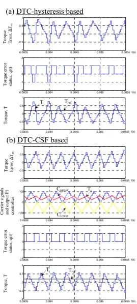
In order to establish a constant switching frequency, the frequency of upper and lower triangular waveforms employed for constant torque controller is set at 4 kHz with a peak-to-peak of 100 units. For PI torque controller, the gain value of Kp and Ki are restricted to ensure the absolute slope of the output signal, Tc does not exceed the absolute slope of triangular carrier [9]. Figure 3 describes the operation of torque control and the performances of torque obtained using DTC-hysteresis based and DTC-CSF based induction machines. It can be seen that, the torque ripple is minimized with almost constant switching frequency achieved in DTC- CSF scheme.
Fig. 1. The control structure of hysteresis-based DTC
Fig. 2. Constant Switching Frequency controller.
0.0835-1 0.084 0.0845 0.085 0.0855
-0.5 0 0.5 1
t(s)
0.0835-2 0.084 0.0845 0.085 0.0855
-1 0 1 2
t(s)
0.0835-1 0.084 0.0845 0.085 0.0855
-0.5 0 0.5 1
t(s)
0.0835-1 0.084 0.0845 0.085 0.0855
-0.5 0 0.5 1
t(s)
0.0835 0.084 0.0845 0.085 0.0855
-100 0 100
t(s)
0.0835-2 0.084 0.0845 0.085 0.0855
-1 0 1 2
t(s)
0.0835-1 0.084 0.0845 0.085 0.0855
-0.5 0 0.5 1
t(s)
Fig. 3. Comparison by simulation of torque control operations for (a) DTC- Hysteresis based (b) DTC-CSF based indution machines.
(a) DTC-hysteresis based
(b) DTC-CSF based
Torque Error, ΔTerTorque error status, q(t)Torque, TTorque Error, ΔTerTorque error status, q(t)Torque, TCarrier signals and output PI controller
T Tref
T Tref
Cupper
Clower
Tc
PEDS2009
III. TORQUE CAPABILITY IN DTC
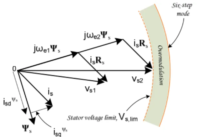
In practice, a rated stator flux and inverter current limit are used to obtain maximum torque capability in DTC of induction machine drive. The inverter current limit is usually 150-200% of rated current machine in order to achieve higher acceleration during transient condition. Fig. 4, shows phasor diagrams of back-emf voltages, stator voltages and stator resistance voltage drops for two different speed operations.
The phasor diagrams were drawn based on (1).
At low speed operation, the back-emf, jωe1Ψs is much lower than the stator voltage limit, vs,lim. In this situation, the DTC algorithm produces sufficient and appropriate voltage vectors vs1 to control both stator flux and torque, simultaneously. At base speed operation, the magnitude of stator voltage touches its limit and the back-emf voltage increases to jωe2Ψs. The base speed is defined as the highest speed at which the maximum torque capability for a rated stator flux can be retained. Notice that, the torque and flux producing current components (in stator flux reference frame), isdΨs
and isqΨs are under controlled for below base speed operation. Thus, the maximum output torque below base speed operation is determined by the current limit of the inverter, assuming no current saturation. In other words, the induction machine can be considered to be controlled by a current source, for below base speed operation. This is also true in the hysteresis-based DTC with decoupled control structure and no current control loop present as oppose in Field Oriented Control (FOC) system.
The capability of torque may reduce as the back-emf voltage increases approaching the stator voltage limit as illustrated in Fig. 5. For convenience, the phasor diagram of stator voltage, back-emf and stator resistance voltage drop at base speed operation is presented again. Obviously, the torque producing current component, isqΨs decreases as the back-emf increases beyond the jωe2Ψs (see vector components represented by arrow with dashed line). On the other hand, the flux producing current component isdΨs is still under controlled in regulating the stator flux at its rated value.
To enhance the output torque capability, a flux weakening method is commonly applied. For example, [2][11] consider voltage and current limits condition to obtain maximum torque capability in the field weakening region. However, this strategy requires a precise current regulation, reference frame transformation and knowledge of machine parameters to derive the optimal controllable currents isdΨs
and isqΨs. Recently, a robust field weakening strategy utilizing hysteresis-based direct torque control was proposed in [4].
The main idea of this scheme is to adjust the flux reference on the basis of torque error. In this way, the appropriate flux level is spontaneously determined and maximum torque capability is obtained as well. This proposed method is less
Fig. 4. Capability of torque retained for below base speed operations.
Fig. 5. Poor torque capability as the back-emf increases approaching the stator voltage limit.
dependent on machine parameters, allowing a satisfying operation in the whole speed range.
In this paper, a simple overmodulation method employed in DTC-CSF is proposed to extend a constant torque region until the increased stator voltage limit reaches at nearly six- step mode. Then, a conventional flux weakening method [8]
is applied when the output torque is considered no longer satisfied its demand. By doing so, the simple control structure of basic DTC scheme can be retained and the maximum torque capability for a wider speed range operation can be achieved, which is an important requirement in many electric drive applications.
IV. EXTENDING THE STATOR VOLTAGE OPERATION TO SIX- STEP MODE
In SVM based system, the overmodulation starts when the reference voltage vector goes beyond the stator voltage hexagonal trajectory. The reference voltage will be modified whenever it goes outside the hexagonal limits. If the modified reference voltage moves along the hexagonal trajectory, the synthesized voltage will have no zero voltage vector.
In DTC hysteresis-based drive, zero voltage vectors will not be selected when the actual (or estimated) torque does not
PEDS2009
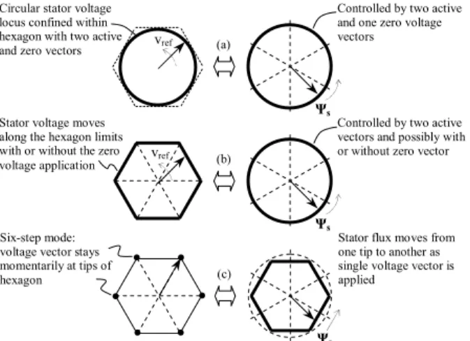
reach the reference torque. In order to fully utilize the DC voltage, the stator voltage magnitude has to go beyond this limit and operate in six-step mode. However with the conventional hysteresis-based structure DTC drive, this is not possible. To go around this problem what we need to do is to modify the output of the stator flux hysteresis comparator so that the selected voltage vector will transform stator voltage to six-step waveform. With regards to the stator flux locus, when the reference voltage is sinusoidal, i.e. within the hexagon, the locus of the stator flux is circular (Fig. 6(a)). As a matter of fact, when the stator voltage vector trajectory moves along the hexagon without any zero voltage vector application, the stator flux locus is still circular (Fig. 6(b)).
This is because without the zero vectors, the stator flux is still regulated by the two active vectors and hence will follow the circular locus reference. The locus, however, begins to change to hexagonal shape as the stator voltage begins to transform to six-step mode. The locus is a completely hexagonal when the waveform of the stator voltage is six-step (Fig. 6(c)). It is therefore possible to extend the stator voltage output to six-step mode by modifying the stator flux locus.
V. PROPOSED OVERMODULATION STRATEGY
The proposed structure of DTC-CSF based induction machines with flux error modification is shown in Fig. 7. The DTC-CSF scheme offers constant switching frequency by replacing the 3-level torque hysteresis comparator in basic DTC-hysteresis scheme [10] with a constant switching frequency controller as reported in [9]. Notice that, most of the component parts in the simple structure of basic DTC hysteresis introduced in [10] are retained, except with the inclusion of the ‘Modification of flux status error’ block which is responsible in performing the overmodulation strategy.
Fig. 6. The mapping of the voltage vector and the stator flux trajectories
Fig. 7. The proposed structure of DTC-CSF based with flux error modification
In the proposed DTC-CSF drive system, there is no SVM involved since there is no voltage reference generated. The overmodulation up to the six-step mode is implemented by exploiting the shape of the stator flux locus. This is done by feeding the look-up table with the modified flux error status.
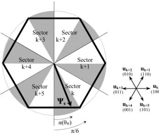
The operation of modification of flux error status can be described as illustrated in the flowchart in Fig. 8. Figure 9 shows the hexagonal shape of stator flux locus where the original flux error status Ψ+ is modified to produce Ψ- during overmodulation mode. The overmodulation starts when the estimated torque does not reach the torque demand. The moment this occurs, the shape of the stator flux is switched to hexagonal. As the speed increases, the back-emf also increases therefore larger stator voltage is needed to satisfy the torque demand. The demand will be naturally fulfilled by the controller which will gradually drops the applications of zero voltage vectors as the speed increases. As the speed is further increased and no more zero voltage vector is available, the selection of voltage vector will naturally transform to a six-step mode. In other words by transforming the stator flux locus to the hexagonal shape, we provide the stator flux locus for hexagonal shape and the torque demand will naturally transform the stator voltage from PWM to six- step mode.
Overmodulation?
Calculate α(θψ)
so that 0 ≤ α(θψ)≤ π/3 for every sector
α(θψ)
greater than π/6 ? Normal DTC
algorithm ψ- = ψ+
Yes No
Yes (ψ+ ≠ ψ-) No
(ψ+ = ψ-)
Get q(t), θψ, ψ+
Ψs decreases by selecting uk+1
for sector k, ψ- = 1
Ψs increases by selecting uk
for sector k, ψ- = 0
Fig. 8. The operation of modification of flux error status
Six-step mode:
voltage vector stays momentarily at tips of hexagon
Stator flux moves from one tip to another as single voltage vector is applied
(c)
Ψs
vref (a)
Ψs
Circular stator voltage locus confined within hexagon with two active and zero vectors
Controlled by two active and one zero voltage vectors
(b) Stator voltage moves
along the hexagon limits with or without the zero voltage application
Ψs
Controlled by two active vectors and possibly with or without zero vector vref
PEDS2009
Fig. 9. The change of flux locus from Circular to hexagonal shape
In contrast, the overmodulation strategy implemented in DTC-SVM requires a precise estimated voltage reference to perform overmodulation while maintaining the flux and torque control. Moreover, a smooth transition of stator voltage from PWM to six-step mode by gradually changing the holding angle from 0 to π/6 rad., is a must to avoid any large sudden change in the output torque [7]. Consequently, these requirements result in complex control structure in DTC-SVM based induction machine drives.
VI. SIMULATION RESULTS
The simulation of the DTC induction motor drive with the proposed overmodulation strategy was performed using MATLAB/SIMULINK simulation package. The DTC-CSF system and induction machine parameters used in the simulation are given as tabulated in Table I.
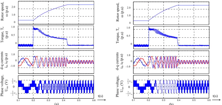
Fig. 10, compares the performances obtained in DTC without overmodulation with that obtained in DTC with the proposed overmodulation method, when a step change of speed reference is applied from 0.5 p.u. to 2.5 p.u.
TABLEI
DTC-CSFSYSTEM AND INDUCTION MACHINE PARAMETERS
DTC-CSF System
Proportional gain, Kp 36
Integral gain, Ki 12643
Flux hysteresis band 0.01 Wb
Sampling frequency 40kHz Switching frequency 4kHz Induction machine
Stator resistance 5.5 Ω
Rotor resistance 4.51 Ω
Stator self inductance 306.5 mH Rotor self inductance 306.5 mH Mutual inductance 291.9 mH Momen of inertia 0.01 kg.m2
Number of poles 4
Rated speed 1410 rpm
DC-link voltage 565 V
In this case, a conventional flux weakening method (a flux reference is varied in proportional to the inverse of rotor speed) is applied in field weakening region. It can be observed that an extension of constant torque region and higher capability of torque in field weakening region are obtained in DTC with the proposed overmodulation method.
Thus a shorter acceleration time is obtained during the speed transient response with the proposed overmodulation method.
In general, the overmodulation mode in DTC produces higher current harmonics content as a result of the hexagonal shape of the stator flux. Apparently, the stator current distortions only occur when the proposed overmodulation method is applied in DTC to achieve higher torque capability and hence rotor to accelerate faster. The PWM mode of stator voltage and current will be operated again as the speed reaches its reference.
Fig. 11, shows the stator flux locus corresponds to the results obtained in Fig. 10. In the proposed overmodulation method, the stator flux locus is suddenly changed to the hexagonal shape. In such manner, the stator flux angular velocity increases as the hexagonal stator flux locus shrinks (flux weakening) as shown in Fig. 11.
Ψs
α(θΨ) π/6 Sector
k Sector
k+1 Sector k+2 Sector
k+3
Sector k+4
Sector k+5
uk+3
(011) uk
(100)
uk+1 (110)
uk+2 (010)
uk+4 (001) uk+5
(101)
PEDS2009
Fig. 10. Waveforms of rotor speed, output torque, d-q stator current components, phase stator voltage and stator flux locus during acceleration, for (a) DTC without overmodulation (b) DTC with the proposed overmodulation.
Fig. 11. Stator flux locus during acceleration speed from 0.5 to 2.5 p.u. for (a) DTC without overmodulation (b) DTC with the proposed overmodulation
VII. CONCLUSION
This paper presents a simple overmodulation method employed in DTC-CSF based scheme. It is shown that, the stator voltage can perform under overmodulation mode by changing the stator flux locus from circular to the hexagonal shape. An extension of constant torque region and higher capability of torque in field weakening region can be obtained with the proposed overmodulation method. The main benefit in the proposed strategy is its simplicity and it can be implemented in many electric drive applications to obtain maximum torque capability for a wider speed range operation.
ACKNOWLEDGMENT
The authors would like to thank the Universiti Teknikal Malaysia Melaka (UTeM) for providing the funding for this research.
REFERENCES
[1] J. Holtz, W. Lotkatz, and A. Khambadkone, “On continuous control of PWM invertersin the overmodulation range in cluding the six-step mode”, IEEE Trans. on Power electronics, Vol. 8, No. 4., pp 546- 553, Oct, 1993.
[2] S. H. Kim and S. K. Sul, “Maximum torque control of an induction machine in the field weakening region,” IEEE Trans. Ind. Appl., vol. 31, no. 4, pp. 787–794, Jul./Aug. 1995.
[3] M. Mengoni, L. Zarri, A. Tani, C. Rossi, G. Serra, D. Casadei,
"Stator Flux Vector Control of Induction Motor Drives in the Field- Weakening Region," IEEE Trans. on Power Electronics, vol. 23, no. 2, March 2008, pp. 941-949.
[4] D. Casadei, G. Serra, A. Stefani, A. Tani, L. Zarri, “DTC drives for wide speed range applications using a robust flux-weakening algorithm,” IEEE Trans. On Industrial electronics, Vol. 54, no. 5, pp.
2451-2461, October 2007.
[5] M. Depenbrock, "Direct Self Control of inverter-fed of induction machine , IEEE Trans. Power Electron., vol3,pp. 420-429, 1988.
[6] Tripathi, A. M. Khambadkone, S.K. Panda, “Dynamic Control of Torque in Overmodulation and in the Field weakening region,” IEEE Transactions on Power Electronics, vol. 21, No. 4, pp. 1091-1098, July 2006.
[7] T. Habetler, F. Profumo, M. Pastorelli, L. Tolbert. “Direct Torque Control of Induction Machines Using Space Vector Modulation”. IEEE Trans. on Industry Applications, 28(5):1045–1053, September/October 1992.
[8] R. Joetten and H. Schierling, “Control of the induction machine in the field weakening range,” Proc. IFAC, 1983, pp. 297-304.
[9] N. R. N. Idris and A. H. M. Yatim “Direct torque control of induction machines with constant switching frequency and reduced torque ripple,” IEEE Trans. Ind. Electron., vol. 51, no. 4, pp. 758–767, Aug.
2004.
[10] Takahashi I, Naguchi T, “A new quick-response and high efficiency control strategy of an induction motor”, IEEE Trans. Industry Appl 22:820–827, 1986.
[11] G. Griva, F. Profumo, M. Abrate, A. Tenconi, and D. Berruti, “Wide speed range dtc drive performance with new flux weakening control [for induction motor drives],” in Proc. 29th Annu. IEEE Power Electron.Spec. Conf. (PESC’98), May 1998, vol. 2, pp. 1599–1604.
-1 -0.5 0 0.5 1
-1 -0.5 0 0.5 1
d-stator flux (p.u)
q-stator flux (p.u)
ωs ω=0.5 p.u
ω=2.5 p.u
(a)
-1 -0.5 0 0.5 1
-1 -0.5 0 0.5 1
d-stator flux (p.u)
q-stator flux (p.u)
ωs ω=0.5 p.u
ω=2.5 p.u
(b)
t(s)
0.1 0.2 0.3 0.4 0.5 0.6
0.1 0.2 0.3 0.4 0.5 0.6
Rotor speed, ω (p.u) Torque, Te (p.u) d-q currents id, iq (p.u) Phase voltage, Usa, (V)
1.0
0 2.0
0.5
1.0 0
1.0
-1.0 0
Udc
3 2
Udc
3
−2
0 Rotor speed, ω (p.u) Torque, Te (p.u) d-q currents id, iq (p.u) Phase voltage, Usa, (V)
1.0
0 2.0
0.5
1.0 0
1.0
-1.0 0
Udc
3 2
Udc
3
−2
0
t(s)
(a) (b)
PEDS2009