A Real-Time DSP-based Driving Assistance and Surveillance System
Bing-Fei Wu, Hsin-Yuan Peng, Chao-Jung Chen, and Yin-Han Chen National Chiao Tung University
{bwu, slight, cjchen, winand}@cssp.cn.nctu.edu.tw
Abstract
Thousands of people are killed or injured in the vehicle accidents which are mostly caused by the carelessness of humans.
Therefore, if there exists a warning system which can notify the driver of the approaching vehicles and the lane departure, the terrible tragedies can be greatly avoided.
Moreover, if the driving status, such as the situation around the vehicle and the drivers’
behaviors, can be recorded in videos, not only in texts, the police officers can reconstruct the scene easily. Furthermore, the increasing numbers of stolen cars is an important issue so the protection of the vehicles is essential. In this paper, a real-time DSP-based driving assistance and surveillance system is proposed. It can manipulate the images to detect the lane and the vehicles in both front and rear directions and the full-time driving status can also be recorded in H.264. After parking, the monitor images inside the vehicle can be transmitted to users’ mobile phones to prevent the thieves. The contribution of this paper is to provide an embedded system to improve the security at all-time, and the drivers, the passengers, and the vehicles can be much safer. The proposed system has been successfully implemented and fully tested by the real road environment in Taiwan so the stability and the reliability can be ensured.
Index Terms : Intelligent transportation Systems, Lane departure, Mobile phone.
I. Introduction
Recently, traffic accident death has a huge increasing, and about 800,000 people died in world-wide road related accidents in 1999[1]. According to the report by the U.S.
National Highway Traffic Safety Administration (NHTSA), falling in asleep while driving is responsible for at least 100,000 automobile troubles annually [2]. In 2000, the situation even gets worse, and 1.26 million people are killed in the tragedies [3].
From the above statistical results, the terrible disasters have been increased dramatically, and the driving behavior is the main reason. The misfortunes can be avoided if the drivers are notified with the real-time warning massages by the driving assistance system (DAS) in a jiffy. Thus, many researchers focus on the developments of DAS to solve these huge problems [4]-[8].
One kind of these systems need several instruments except cameras to deal with the input information [4]-[6]. Wijesoma et al.
use radar to scanning the lane status [4]. If the driving conditions are classified as the irregular cases, the system will trigger the warning massages. Besides, the car accidents are not only caused by the lane departure, but also by the inappropriate distances between vehicles. DDAS, proposed by Sheu et al., is able to provide useful surrounding information, such as directions and distances to nearby vehicles, to drivers, so unnecessary collisions could be avoided, especially in cases of changing lanes, crossing intersections, and making turns [5]. The main idea of [5] is to install
DDAS in all cars, so the vehicles can detect each other by the smart antennas to exchange the data to maintain the proper behaviors. Moreover, in the advanced safety vehicles (AVS) project of Toyota, the driver must wear a wristband in order to measure his heart rate, and Mitsubishi has reported the use of steering wheel sensors to measure the vehicles' behavior to detect if the drivers drowse or not in their AVS system [6]. However, these systems may not be practical since they need more equipments, which will lead to increase the cost and the limitation compared to the general image-based processing system.
The other kind methods are based on the help of the machine vision, and they only require several cameras and the process units to compute the driving safety assist algorithms. Hayami et al. use eye's status to adjudge the drivers' behavior to distinguish whether they are drowsiness or not [7]. In the algorithm of [7], few parameters are roughly calculated so the precision is not good enough to provide the safety. In order to increasing the degree of accuracy and the robustness, more complex equations are calculated in [8]. Although the performance has been promoted, its computational complexity also increases comparatively. These methods can mainly solve the problems that the drivers fall in asleep, but not the irregular driving behaviors caution. If the motorists are talking on the phones or having a daydream, they won't doze. However, the dangerous actions such as lane departure will be produced.
Several lane departure warning systems (LDWS) based on the variety of the computer vision techniques have been proposed [9]-[13]. The main principles of these different technologies are to detect whether the vehicles are in some risky conditions. When the systems find that the cars are in some irregular statuses, it will alarm the drivers by generating warning signals like making a huge sound or a blinking light. Most algorithms only can run
on personal computers or work stations due to the complexity, and it is not acceptable in real application such as buses, trucks and movable cars because of the limited space and the restricted power supplement. In order to avoid these drawbacks, the modified schemes for the embedded systems are proposed [14]-[16]. In [15], an ARM-based system is provided to act as an LDWS, and it has a major advantage of the cost and the power consumption. However, its computational load is very weak, 128x128 at 22 frames per second (FPS). For the huge input image information, a system adds field programmable gate array (FPGA) device to increase processing speed [14]-[16]. The quasi-system based on Power PC is also proposed [17], and it uses a high performance core and a small machine box to form a mini-system. Although these solutions can overcome the complicated computations and finish the particular works, the system is hard to change if users or programmers want to modify or add some functions in the future. For example, the system needs to modify the algorithms for the signs of velocity-limitation which are different in U.S.A. and Asia.
The above works are used to prevent the accidents, but they can not provide useful information for users and police officers when the misfortunes happen. The vehicle box, proposed by Yeh et al., is designed to keep track of the vehicles and the driving information, which is analogous o the flight data recorder used in aircrafts [18]. Since it takes down the GPS data, it can reconstruct the car's location, speed, and orientation. However, it can not reveal the exact causes.
All of these works lacks the real-time notification which can greatly help the drivers, and the driving status that can analyze the reasons of the accidents [4]-[18].
Moreover, these systems can only protect the users and the vehicles when they are moving. When the vehicles are parked, the users still have to face the opportunity of missing them. In this study, a real-time
digital signal processor (DSP) based driving assistance and surveillance system (DASS) is implemented. For the considerations in both flexibility and computing power, the DSPs with strong calculation, addition and multiplication, are good choices for the vehicular electronics. The system is combined by two independent DSP sub-systems, which are the lane departure and vehicle detection warning system, LVWS, and the mobile surveillance recorder, MSR, and is realized by TI DM642 and OMAP5912, respectively. The algorithms on LVWS works not only for the front view but also the rear direction, and can manipulate the real-time images from these two channels simultaneously in CIF at 30 frames per second. MSR is responsible for recording the full-time driving status with H.264 video compression algorithm, and it also provides the monitoring functionalities using cell phones. When the vehicle is driving away from the road or is too close to the other cars, LVWS will generate a warning signal and transmit it to MSR by the Zigbee wireless communication. The main advantages of using Zigbee are to simplify the installation of DASS and save the space which is strongly restricted in the vehicles. As soon as LVWS receives the caution information, it will produce short messages to the mobile phones of the related people, such as their families or companies.
Then, they can browse the real-time images from MSR with their mobile phones anytime and anywhere and caution the driver or request the police for help in order to avoid a possible accident. Furthermore, if the motorist is in distress, the video recorded by MSR can help the police to recover the original condition. Furthermore, if the vehicle happened to an accident, such as dropping down the mountain valley or being capsizing, MSR will call for help automatically to reduce the waiting time and greatly increase the survival rate. Moreover, when the vehicles are parked, the owners can receive the images from MSR to protect their properties. The main contribution of this paper is to provide a total solution
which integrates the innovative functions in an embedded system to furnish the users full-time protection. No matter the drivers, the passengers, and the vehicles are moving or not, their safety are ensured.
The rest of this paper is organized as follows. In Section II, The innovative functional schemes of DASS are presented.
Section III describes the software of LVWS and MSR. DASS is tested on different real conditions, and the relative results are shown in Section IV. Finally, the conclusions are given in Section V.
II. The Innovative Functional Schemes of DASS
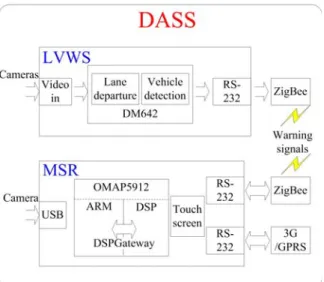
An overall system block diagram of DASS is depicted in Fig. 1. LVWS combines two cameras, a DM642 platform, and a Zigbee device. The cameras are responsible for capturing the real-time information and send them into DSP, and when the manipulation results determine that the vehicle is in danger, the warning signal will be transmit to MSR via the Zigbee device. The major function of LVWS is to detect the lanes and the vehicles in both front and rear views. MSR includes a touch screen module, a USB camera, a CF storage card, and a GPRS module. The camera will input the images in the vehicle, and the OMAP processor will compress them with the format of H.264 in the CF storage card.
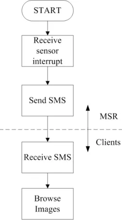
When MSR receive the warning signal from LVWS, it will send the warning short message to the mobile phones that set by the users. As soon as the cautions are received, the cell phone can browse the real-time image in the vehicle anytime and anywhere.
The functional schemes of DASS are described as follows.
Fig. 1 An overall system block diagram of DASS
A. Active real-time image-based lane departure and vehicle detection warning system for both front and rear views
With the platform-dependent optimizations of the memory and the enhanced direct memory access (EDMA) management, the complex algorithms that can perform real-time vehicle detection and lane departure warning for both front and rear views are implemented. LVWS can determine whether the vehicle is deviating from the road or is too close with other cars, and generate the caution signals. In the different conditions, such as sunny, cloudy, rainy days and night, the information of lanes and the vehicles can be successfully obtained. The main reason for the vehicle accidents is the irregular driving behaviors, and the normal warning system can only produce sound or blinking lights which are not enough for protection. LVWS can transmit the warning message to the police department or the family people of the driver, and they can notify them before the tragedies. The whole flow is shown in Fig.
2.
B. H.264 driving status recorder
If the drivers are in danger, the reasons
Fig. 2 The flowchart of the active real-time vehicle detection and lane departure warning
system
that cause the accidents are the most important part. The driving status recorders are not popular nowadays, and they can only provide the data of throttle and the brake which are not able to reconstruct the situation. MSR can record the full-time driving status in H.264, which is suitable for a stand-along system since its video quality and its compression ratio are very high, in the CF storage card, and the video recorded by MSR can help the police or the related departments for reference. The state chart of the system is illustrated in Fig. 3.
Fig. 3 The flowchart of the full-time recorder
C. Burglarproof with mobile surveillance The recent vehicle surveillance systems, such as On Star [19] in USA, TOBE [20] in Taiwan, can provide the latest information of your car by short text messages. However, in the current applications, no matter the short message or the GPS navigation, both can not provide the lawless persons' pictures. The users can only know there is something happened in their vehicles, but they can not know what exactly the situation is. Maybe there really exists thieves or just a heavy truck goes by. Therefore, a burglarproof system with mobile surveillance and
friendly user interface for mobile devices are developed to clear the above drawbacks. It can access the internet by 3G/GPRS so that the server can be installed in the vehicles, not restricted by the wired-internet environment. When the intruders try to steal your vehicles, MSR will transmit the warning short messages to users' mobile phones. As soon as the users receive the cautions, they can browse the real-time images in the vehicle anytime and anywhere.
In addition, the software in the mobile clients is very easy to use. The users simply press one button to browse the continuous pictures. Thus, it can supply the all service functions through 3G/GPRS communication to help the vehicle owner understanding their vehicle conditions, and the program flowchart is shown in Fig. 4.
Fig. 4 The flowchart of the mobile surveillance system
III. The Software of LVWS and MSR
In this section, the relative algorithm
which includes the lane and vehicles detection of LVWS and H.264 video encoding algorithm in MSR are addressed.
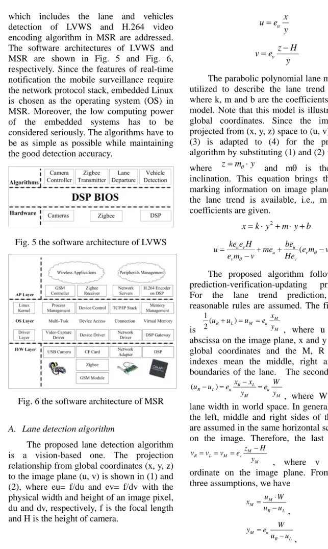
The software architectures of LVWS and MSR are shown in Fig. 5 and Fig. 6, respectively. Since the features of real-time notification the mobile surveillance require the network protocol stack, embedded Linux is chosen as the operating system (OS) in MSR. Moreover, the low computing power of the embedded systems has to be considered seriously. The algorithms have to be as simple as possible while maintaining the good detection accuracy.
Fig. 5 the software architecture of LVWS
Fig. 6 the software architecture of MSR
A. Lane detection algorithm
The proposed lane detection algorithm is a vision-based one. The projection relationship from global coordinates (x, y, z) to the image plane (u, v) is shown in (1) and (2), where eu= f/du and ev= f/dv with the physical width and height of an image pixel, du and dv, respectively, f is the focal length and H is the height of camera.
u
u e x
= y
(1)
v
z H v e
y
= −
(2) The parabolic polynomial lane model is utilized to describe the lane trend in (3), where k, m and b are the coefficients of this model. Note that this model is illustrated in global coordinates. Since the image is projected from (x, y, z) space to (u, v) plane, (3) is adapted to (4) for the proposed algorithm by substituting (1) and (2) into (3), where z=mθ ⋅y and mθ is the road inclination. This equation brings the lane marking information on image plane when the lane trend is available, i.e., m and b coefficients are given.
x= ⋅k y2+ ⋅ +m y b (3)
( )
u v u
u v
v v
ke e H be
u me e m v
e mθ v He θ
= + + −
− (4)
The proposed algorithm follows the prediction-verification-updating principle.
For the lane trend prediction, three reasonable rules are assumed. The first one is
1( )
2
M
R L M u
M
u u u e x
+ = = y
, where u is the abscissa on the image plane, x and y are the global coordinates and the M, R and L indexes mean the middle, right and left boundaries of the lane. The second one is
( R L) u R L u
M M
x x W
u u e e
y y
− = − =
, where W is the lane width in world space. In general cases, the left, middle and right sides of the lane are assumed in the same horizontal scan line on the image. Therefore, the last rule is
M
R L M v
M
z H
v v v e
y
= = = −
, where v is the ordinate on the image plane. From these three assumptions, we have
M M
R L
u W
x u u
= ⋅
− , (5)
M u
R L
y e W u u
= − , (6)
u M M
R L v
e v W
z H
u u e
= + ⋅ ⋅
− , (7) it yields
2 2
( ) ( ) ( )
M R L u u R L R L
u u u ke W me u u b u u
− = + − +W −
(8) for lane trend prediction. The least square approximation is applied for the obtaining of the coefficients k, m and b. The one has to be mentioned is that (8) works when W is given. The calculated k, m and b will assist in getting the lane marking coordinates by substituting them into (4). In the lane marking detection, the intensity of the lane markings are applied with its dark-light-dark (DLD) characteristic, as shown in Fig. 7(a).
The point M is located at the DLD transmission if the intensity of M, IM
, exceeds that of its left and right side neighbors by half of lane marking width on image plane, MI/ 2, as shown in Fig. 7 (b).
The points L and R are defined if L and R own the maximum gradients in the
[M −MI/ 2,M) and (M M, +MI/ 2]
intervals, respectively, in Fig. 7(c). Once L and R are picked, LR is taken as lane marking in Fig. 7(d) ifLR>LRth, where
LRth
is a predefined threshold. Note that R of the left hand LR is chosen as the marking coordinate and L of the right hand
LR stands for the one.
The last step in the detection algorithm is the parameter updating. mθ
and W are the two parameters for the automatic online calibration.
The lane trend prediction plays a key role in this algorithm. Since we have
z=mθ ⋅y , where e m v
e H y
v
v ⋅ −
=
θ and
v m e
H e m z
v
v ⋅ −
= ⋅
θ θ
, (9) is obtained for parameter calibration, where Czy0=ev⋅mθ and Czy1=evH/euW.
0 1
M zy zy
v =C −C ⋅ Δu
(9)
Fig. 7 Lane marking detection
The weighted least square method yields the coefficients Czy0 and Czy1 in (9) and afterward mθ
and W are available by the inverse calculation. The lateral offset, O(y), is according to the coefficients in (3), k, m, and b, by (10), where y is set as the desired distance ahead the vehicle. The warning signal will be generated whenO(y)≥0.25W.
( ) 2
O y = ⋅k y + ⋅ +m y b (10) B. Vehicle detection algorithm
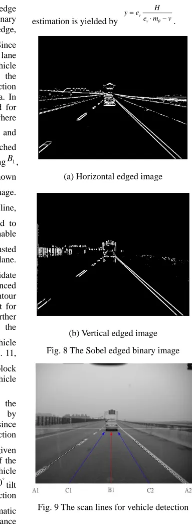
Vehicle detection is combined with the lane detection. The Sobel edge detection is
applied in the vertical and horizontal edge identification. Figure 8 shows the binary images of horizontal and vertical edge, respectively (Edgeh
and Edgev
). Since the host lane area is acquired from the lane detection in A, the searching area for vehicle is limited in the host lane to reduce the computing burden, i.e., the edge detection only be processed in the host lane area. In this area, three scan lines are assumed for vehicle detection in Fig. 9, where
2 )
( 1 2
1 A A
B = + , C1 =(A1+B1) 2 and 2
)
( 1 2
2 B A
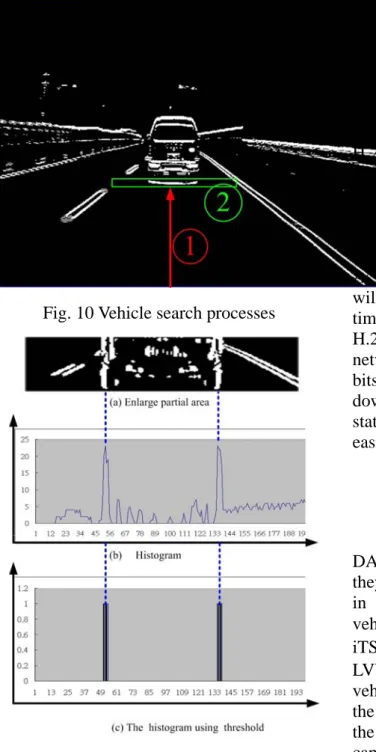
C = + . The vehicle is searched with the continuous horizontal edge alongB1, C1 and C2 from bottom to top. As shown in Fig. 10, this is a Edgeh
binary image.
Once some Edgeh
appears on the scan line, the continuous Edgeh
will be checked to confirm if the vehicle exists. The reasonable width of this continuous Edgeh
is adjusted with the ordinate on the image plane.
Referring to this Edgeh
, a vehicle candidate block is assigned for the advanced identification. In this block, the tire contour for daytime and the light from taillight for nighttime are the features for the further detection of vehicle. Furthermore, the
Edgev
pair is a key feature for vehicle position identification. As shown in Fig. 11, the Edgev
histogram in the candidate block gives two peaks which indicate the vehicle side boundaries.
The distance estimation between the preceding and the host vehicles by vision-based system has much error since the vehicle vibrations and the projection distortion. The road inclination,mθ
, is given another description as the tilt angle of the camera, which exists when the vehicle vibrates even it has be calibrated to 0 tilt ° angle. In the presented lane detection algorithm, mθ
is calibrated automatic online, the more accuracy distance
estimation is yielded by e m v
e H y
v
v ⋅ −
=
θ .
(a) Horizontal edged image
(b) Vertical edged image Fig. 8 The Sobel edged binary image
Fig. 9 The scan lines for vehicle detection
Fig. 10 Vehicle search processes
Fig. 11 The vertical edge histogram
C. The software architecture of MSR
With the rich functionalities, the software architecture of MSR is illustrated in Fig. 6. The embedded OS is responsible for handling the schedule of the software and the control of the hardware. In Fig. 6, MSR can be separated into three layers, the application, the OS, and the hardware layers, and each layer has its dedicated works. The Zigbee receiver can input the interrupt signal when the data is transmitted from LVWS to
MSR, and process the data to distinguish whether the vehicles are safe or danger. The GSM controller can send the warning short messages and connect to the internet via 3G/GPRS to pass the images input by the USB camera to users' mobile phones through the GSM module. Furthermore, the H.264 video encoding algorithm is manipulated by DSP, and it acts as a device of ARM through the DSPGateway. When ARM grabs a picture from the USB camera via the device driver, it will generate an interrupt to DSP to enable it for encoding.
As soon as DSP starts to compress, ARM will capture the next image to reduce the time for data fetching, and perform the H.264 framework in pipeline. Moreover, the network servers can streaming out the bitstream on the fly, and can let the users download the files to reconstruct the driving status by the general internet browsers easily.
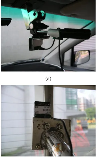
V. The Implementation Results All functionalities and the system of DASS are successfully implemented, and they are tested by the real road environments in Taiwan. DASS is well installed in the vehicle, which is called “TAIWAN iTS-1" in Fig. 12, and the cameras of LVWS are placed in front and back of the vehicle, shown in Fig. 13. On the other hand, the USB camera of MSR is also planted in the right-front of the vehicle in order to capture the images of the driving status, and the position is illustrated in Fig. 14. The testing results include series of the conditions such as general cases, rainy days, complicated roads, and the interference of the windshield wipers and the lights. The experimental results of each function are described below.
Fig. 12 TAIWAN iTS-1
(a)
(b)
Fig. 13 The monochromatic CCD mounted behind the (a) front (b) rear windshield
Fig. 14The USB CCD mounted behind the right front windshield
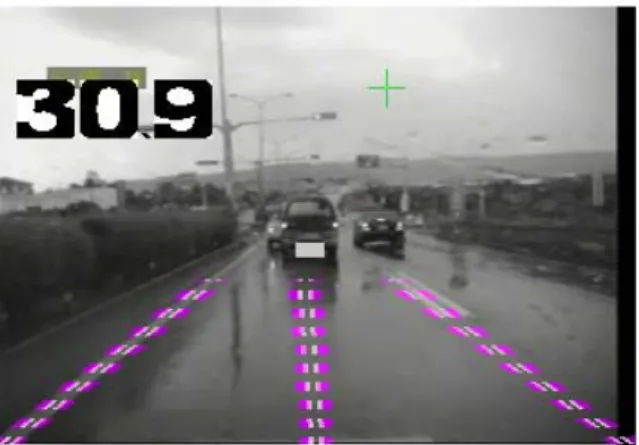
A. Lane departure and vehicle detection algorithms
The lane departure and the vehicle detection algorithms are verified, and the results of lane marks and the vehicles in both front and rear direction, which are shown in Fig. 15 to Fig. 18, are located simultaneously. In Fig. 15 to Fig. 18, the results in general cases, rainy days, complex roads, curved roads, and night are depicted, and LVWS can successfully manipulate the desired outcomes at 30 FPS. In average, the correctness ratio of the vehicle detection is tested, and it is about 94%, 90 % and 88% in the distance of 30 meters, 40 meters and 50 meters, respectively. In locating the lane marks, it can up to 99% in every condition.
These statistics shows the algorithms in LVWS are robust and suitable for the real world.
(a)
(b)
Fig. 15 Detection in the front view, (a) general case (b) rainy day
(a)
(b)
Fig. 16 Detection in the rear view (a)general case. (b)complex road
(a)
(b)
Fig. 17 Detection in the front view (a) curved road (b) night.
(a)
(b)
Fig. 18 Detection in the front view (a) interference of windshield wipers. (b) interference of strong light in rainy days.
B. Real-time notification by the cooperation with LVWS and MSR
When the drivers have illegal behaviors, such as lane departure, LVWS will generate a warning signal to MSR, and the
“Warning" text is displayed on the panel, which is shown in Fig. 19. In DASS, when the vehicle is deviating for longer than 3 seconds, MSR will send the caution short message to the mobile phones which set by the users. In our tests, the message will be received within 3 seconds, which means that if the drivers are in danger, the notification will be produced in 6 seconds. The outer users can browse the real-time driving status to decide to call the police for help or not.
(a)
(b)
Fig. 19 (a) The real-time output in screen. (b) The warning massage is shown in the
OMAP5912 panel.
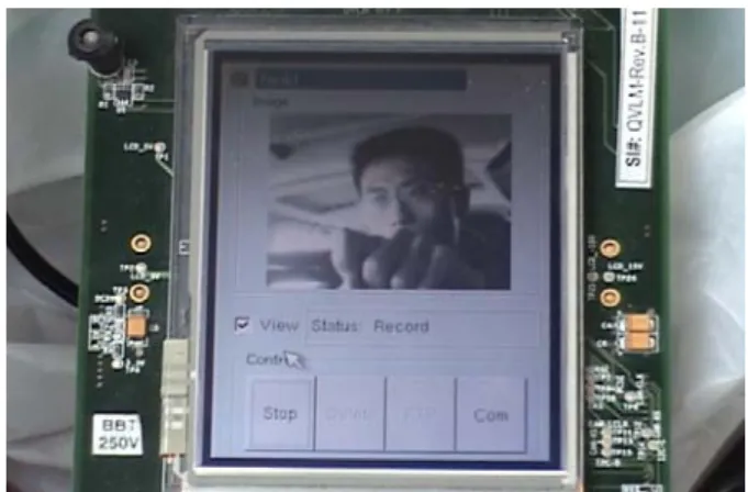
C. Full-time driving status recorder
MSR begins to record the driving status as soon as the vehicle starts, and the encoded bitstream will be stored in the CF storage cards with the H.264 format. If the terrible accidents happened, the files can be downloaded from the general web browser, such as the internet explore (IE), Mozilla firefox, and Netscape, or directly read them in the CF cards. They can be played with the normal media player, and since the driving status does not contain lots of motion, the frame rate can up to 8 FPS which is enough for reconstruct the original condition. Fig.
20(a) shows the recording procedure during the vehicle is moving, and Fig. 20(b) illustrates the compressed file played by the PC.
(a)
(b)
Fig. 20 (a) The real-time image is recorded by OMAP5912. User can review the image
from (b) by internet browser.
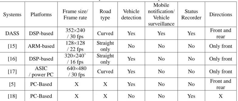
Table I The comparison between different systems Systems Platforms Frame size/
Frame rate
Road type
Vehicle detection
Mobile notification/
Vehicle surveillance
Status
Recorder Directions DASS DSP-based 352×240
/ 30 fps Curved Yes Yes Yes Front and
rear [15] ARM-based 128×128
/ 22 fps
Straight
only No No No Only front
[16] DSP-based 320×240+ / 16 fps
Straight
only Yes No No Only front
[17] ASIC / power PC
640×480
/ 30 fps Curved Yes No No Only front
[5] PC-Based X X Yes No No Front and
rear
[18] PC-Based X X No No Yes X
+The author uses the skill of region of interesting to cut a suitable area.
D. Mobile surveillance system
When the vehicle is parked, the mobile surveillance system is activated. The users can know the circumstances of their properties anytime and everywhere. The Java program developed for mobile phones enables users to see real-time images through the 3G/GPRS protocol. Images are transmitted from MSR so that if someone is sensed by the settle sensors, a short message is sent to the user to notify of an emergency.
The Java applet on their mobile phone shows the real-time continuous QCIF images on the screen, and the result is shown in Fig. 21. However, the actual average bandwidth of 3G is approximately 150K to 200K bits per second for the downloading data transmission rate. The QCIF JPEG image size is approximately 5K bytes so that the mobile phone can download the compressed image data from MSR and display the decoded JPEG image at 3 FPS. The processing time will be reduced if 3G can gain a faster download speed.
Fig. 21 Mobile surveillance
E. Comparisons
Finally, the comparisons in functionalities between several different systems are shown in Table I, and [15]-[17]
can perform the lane departure algorithm.
[17] has the highest performance in LDWS, but the platform is too expensive.
Furthermore, it can only detect the lane marks and the vehicles in the front view, and it lacks the mobile notification and surveillance functions. [15] and [16] are embedded processor-based systems which can greatly reduce the cost and the power consumption. However, the achievements in LDWS can be improved, since they can only locate the straight roads which are not robust
enough to provide better safety assist.
Besides, the approaching vehicles are also latent dangers. [5] can detect the vehicles in both front and rear directions, but it has to be installed in at least two cars to take effect.
The operative distance of [5] is not far enough to meet the requirement of the real road environment at high driving speed. If the accidents happen, the vehicle status recorder can analyze the condition helpfully.
[18] is equipped with a GPS receiver, and it can obtain vehicle's location, velocity, and orientation periodically. Nevertheless, it can not show the real causes of the casualty, and the GPS data can only update once per second which is not quick enough to track the instant status. DASS can manipulate the LDWS in 352x240 at 30 FPS in both front and rear directions, and it is a low-power and stable DSP-based system, which is very suitable for installing in the vehicles. It can adapt the conditions of curved roads, complex roads, rainy days, cloudy days, and night. Besides, DASS can film the situation to provide the facts to the users and the police officers, and they can easily and quickly understand the reasons. Furthermore, DASS provides an innovative function that no other system has – mobile notification and surveillance, which is useful for keeping the thieves away from users' properties.
With these full-time safety assist features, DASS can establish a safer driving and parking environment.
VI. Conclusions
In this paper, DASS with the lane and vehicle detection in both front and rear views of several conditions, such as general cases, rainy days, complex roads, curved roads, and nights, are implemented. Unlike other systems that can only provide single function, DASS also develops three main safety assist features, which are real-time notification by the cooperation with LVWS and MSR, full-time driving status recorder, and mobile surveillance system. DASS can protect the users and the vehicles whenever
they are moving or not, and it has been successfully verified for hundreds of kilometers on Highway No.3 and Expressway No.68 in Taiwan.
Acknowledgment
This work was supported by National Science Council under Grand no. NSC 95-2752-E-009-012-PAE, and Aiming for the Top University Plan of the National Chiao Tung University and Ministry of Education, Taiwan, under Grant 95W803E.
References
[1] G. Jacobs, A. Aeron-Thomas, and A.
Astrop, “Estimating global road fatalities,” Australian National University, Transport Research Laboratory, Technical Report TRL 445, 1999.
[2] D. Royal, “Volume I -Finding report;
national survey on distracted and driving attitudes and behaviors, 2002,” The Group Organization, Washington, D.C., Tech. Rep. DOT HS 809 566, Mar. 2003.
[3] J. Hagen., “Road safety crisis,” UN Chronicle Online Edition., 2004, http://www.un.org/Pubs/chronicle/2004/
webArticles/012204\_road\_safety.asp
[4] W. S. Wijesoma, K. R. S. Kodagoda, and A. P. Balasuriya, “Road-boundary detection and tracking using ladar sensing,” IEEE trans. on Robotics and Automation, Vol. 20, Issue 3, pp.
456-464, June 2004.
[5] Shiann-Tsong Sheu, Jung-Shyr Wu, Chi-Hao Huang, Yen-Chieh Cheng and Lu-Wei Chen, “DDAS: Distance and
Direction Awareness System for Intelligent Vehicles,” Journal of Information Science and Engineering, Vol. 23, pp. 709-722, 2007.
[6] A. Kircher, M. Uddman, and J. Sandin,
“vehicle control and drowsiness,”
Swedish National Road and Transport Research Institute, Linkoping, Sweden, Tech. Rep. VTI-922A, 2002.
[7] T. Hayami, K. Matsunaga, K. Shidoji, and Y. Matsuki, “Detecting drowsiness while driving by measuring eye movement - a pilot study,” in proceeding of IEEE Intelligent Vehicles Symposium, pp. 156-161, Sept. 2002.
[8] L. M. Bergasa, J. Nuevo, M. A. Sotelo, R. Barea, and M. E. Lopez, “Real-time system for monitoring driver vigilance,”
IEEE trans. on Intelligent Transportation System, Vol. 7, Issue 1, pp. 63-77, Mar. 2006.
[9] V. Kastrinaki, M.Zervakis, and K.
Kalaitzakis, “A survey of video processing techniques for traffic applications,” Image and Vision Computing, vol. 21, no. 4, pp. 359-381, April 2003.
[10] J. W. Lee, C. D. Kee, and U. K. Yi, “A
new approach for lane departure identification,” in proceeding of IEEE Intelligent Vehicles Symposium, Columbus, OH, June 2003, pp. 100-105.
[11] S. Y. Kim and S. Y. Oh, “A adaptive lane departure warning system based on image processing and a fuzzy evolutionary technique,” in proceeding of IEEE Intelligent Vehicles Symposium,
Columbus, OH, June 2003, pp. 361-365.
[12] K. Weiss, N. Kaempchen, and A.
Kirchner, “Multi-model tracking for the detection of lane change maneuvers,” in proceeding of IEEE Intelligent Vehicles Symposium, Parma, Italy, 2004, pp.
937-942.
[13] C. R. Jung and C. R. Kelber, “A lane
departure warning system based on a linear-parabolic lane model,” in proceeding of IEEE Intelligent Vehicles Symposium, Parma, Italy, 2004, pp.
891-895.
[14] J. Kaszubiak, M. Tornow, R. W. Kuhn, B.
Michaelis, and C. Knoeppel, “Real-time vehicle and lane detection with embedded hardware,” in proceeding of IEEE Intelligent Vehicles Symposium, June 2005, pp. 619-624.
[15] P. Y. Hsiao, C. W. Yeh, “A Portable Real-Time Lane Departure Warning System based on Embedded Calculating Technique,” in proceeding of IEEE Vehicular Technology Conference, 2006, pp. 2982-2986.
[16] C. H. Yeh and Y. H. Chen,
“Development of vision-based lane and vehicle detecting systems via the implementation with a dual-core DPS,”
in proceeding of IEEE Intelligent Vehicles Symposium, Sep. 2006, pp.
17-20
[17] http://www.mobileye.com/asp4.shtml
[18] Han-Chun Yeh, Su-Ying Chang,
Tuan-Sheng Chu, Chien-Wei Chen and Chi-Sheng Shih, “Vehicle Information Systems Integration Framework,”
Journal of Information Science and Engineering, Vol. 23, pp. 681-695, 2007.
[19] http:// www.onstar.com
[20] http:// www.tobe.com.tw