Dynamic Characteristics of Digitally Controlled Buck-Boost DC-DC Converter
Fujio Kurokawa
Nagasaki University Nagasaki, 852-8521 Japan [email protected]
Taku Ishibashi
Nagasaki University Nagasaki, 852-8521 Japan [email protected] Abstract – The purpose of this paper is to present the
dynamic characteristics of the digitally controlled buck-boost dc-dc converter. Furthermore, the relationship between the parameters of control circuit and the dynamic characteristics is discussed. We examine the design criterion to improve the dynamic characteristics. As a result, it is revealed that the wide range of input voltage is realized by setting not only the appropriate filter but also the suitable gain in the digitally controlled buck-boost dc-dc converter.
Index Terms-- Buck-boost DC-DC converter, Digital control, FIR filter
I. INTRODUCTION
Recently, the power supply system plays the important role of renewable energy systems controllability. The high controllability and monitoring function are required in the switching power supply to improve the energy management performance of these systems.
In switching dc-dc power converters, analog control circuits have been widely used. The analog control circuit has many superior characteristics for example fast response, high accuracy, low cost and so forth. However, over the last few years, a considerable number of studies have been made on a digital control [1]-[6]. One reason is that this technique will lead to a future high performance smart power converter and its power management technique.
On the other hand, the buck-boost dc-dc converter has been receiving increasing attention because this type converter is able to control a wide range voltage of the source.
This paper presents the dynamic characteristics of the digitally controlled buck-boost dc-dc converter. Furthermore, the relationship between the parameters of control circuit and the dynamic characteristics is discussed. After reviewing the fundamental configuration of digitally controlled dc-dc converter with the minimum phase FIR filter control[7] and its operation principle, we analyze the dynamic characteristics of digitally controlled buck-boost dc-dc converter. Furthermore, we discuss the design criterion to improve the dynamic characteristics. The key point of this paper is to describe the possibility to realize the high performance and stable digitally controlled buck-boost dc-dc converter using DSP.
II. CIRCUIT CONFIGURATION AND OPERATION PRINCIPLE Figure 1 shows the block diagram of the proposed digitally controlled buck type dc-dc converter using DSP. Ei is the input voltage, eo is the output voltage and io is the output current. Tr is the main switch, D is the fly wheel diode, L is the energy storage reactor, C is the output smoothing capacitor and R is the load. The output voltage eo is sent to the A-D converter through the anti-aliasing filter and is converted into digital amount Nn. The relation between the input and output values of the A-D converter is given by equation (1) when it approximately shows the linear expression by considering the width of the quantization to be small.
o AD
n G e
N = (1) where n denotes an n-th switching cycle, and the digital amount Nn is a positive integer number. GAD is a gain of the A-D converter.
The digital amount Nn is sent to DSP. In DSP, the numerical value NTon that corresponds to the on-time interval Ton is calculated. The relation between the on-time interval Ton and the numerical value NTon is shown as follows;
Ts 1 n Ton S
1 n on
N N T
T + +
= ,
,
(2) where NTs is a numerical value corresponding to the switching period Ts (=1/fs). NTs is calculated in the PWM signal generation circuit which is composed of a digital comparator or a counter. According to the relation between the on-time interval Ton and the numerical value NTon, Ton is generated. This Ton regulates the output voltage eo.
The on-time interval NTon of the minimum phase FIR filter control circuit is represented as follows [7];
( )
∑= − −
− + =
q 0
i hi Nn i NR B K
1 N n ,
NTon
(3)
where K is proportional gain, hi denotes the digital filter coefficients and q is the amount of the sampling points.
III. TRANSIENTRESPONSE
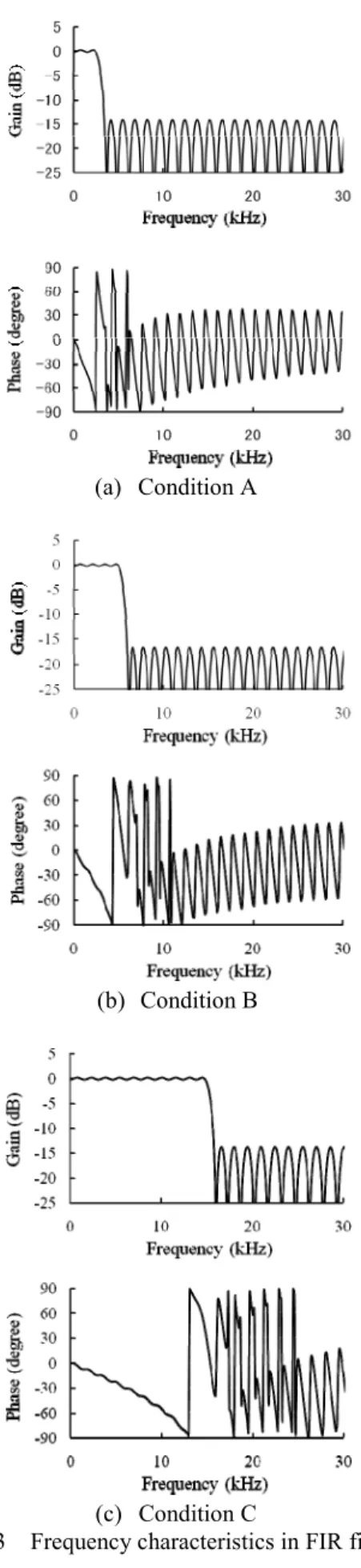
Table 1 shows the parameters in each condition and the parameters is noted in Fig. 2. Figure 3 shows the frequency
PEDS2009
300
characteristics corresponding to each condition. Figures 4(a) through (c) show the simulated transient response of the dc- dc converter with digital control in step change of the load resistor R from 100Ω to 10Ω in each condition. The simulator is PSIM. The switching frequency is 100 kHz. The circuit parameters are Eo*=10V, L=260μH, C=1400μF and the leakage inductance is 4μH.
Fig. 1 Block diagram of digitally controlled buck-boost type dc-dc converter using DSP.
TABLE 1 Parameters in each condition.
Fig. 2 Frequency characteristics of FIR filter.
(a) Condition A
(b) Condition B
(c) Condition C
Fig. 3 Frequency characteristics in FIR filter.
Condition A Condition B Condition C
2.5 5 15
1
3.5 6 16
Pass band Frequency (kHz)
Transition band (kHz) Stop band Frequency (kHz)
1 1
PEDS2009
301
Figure 4 shows simulated transient response in case of Ei = 10V. In Condition A, the transient time Tst is 1.2ms and the steady-state error is 167mV. In Condition B, the transient time Tst is 0.8ms and the steady-state error is 119mV. In Condition C, the transient time Tst is 0.7ms and the steady- state error is 110mV.
In the Conditions A, B and C, the values of under shoot are almost same. However, the ripple and steady-state error is smallest in Condition C. So, the good transient response is realized in Condition C because the pass band frequency is high.
(a) Condition A
(b) Condition B
(c) Condition C
Fig. 4 Transient response in case of Ei=10V.
Figure 5 shows the simulated transient response in case of Ei=5V and Condition C. The steady-state error is 581mV and is very large. Figure 6 shows relationship between the gain and steady-state error in case of Ei=5V and Condition C.
It is seen that the steady-state error depends on the gain.
So, we must set the large gain when the input voltage is low.
Figure 7 shows the transient response in case of Ei =5V and Condition C. K is equal to 10. Even if Ei is small, the steady-state error becomes small by increasing the gain in this way.
Fig. 5 Transient response in case of Ei=5V and Condition C (K=3).
Fig. 6 Relationship between Gain and Steady-state error in case of Ei=5V and Condition C.
Fig. 7 Transient response in case of Ei=5V and Condition C (K=10).
PEDS2009
302
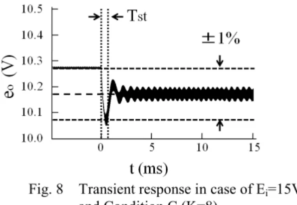
Fig. 8 Transient response in case of Ei=15V and Condition C (K=8)
Figure 8 shows the simulated transient response in case of Ei=15V and Condition C. K is equal to 8. The under shoot is 123mV, Tst is 0.6ms. A good result is provided in this way when the Ei is smaller than Eo by setting an appropriate filter and gain.
CONCLUSION
The above discussion suggests the design criterion of digital control circuit of buck-boost converter with the minimum phase FIR filter control.
It is concluded that the minimum phase FIR filter controlled buck-boost dc-dc power converter has superior dynamic characteristics when the pass band frequency is high.
Moreover it is revealed that the wide range of input voltage is realized by setting notonly the appropriate filter
but also the suitable gain in the digitally controlled buck- boost dc-dc converter.
We confirm that these results are useful to realize the next generation model of the switching power supply for the renewable energy source.
ACKNOWLEDGMENT
This work is supported in part by the Grant-in-Aid for Scientific Research (No.21360134) of JSPS (Japan Society for the Promotion of Science) and the Ministry of Education, Science, Sports and Culture.
REFERENCES
[1] D. Maksimovic, R. Zane and R. Erickson: "Impact of digital control in power electronics," Proceedings of- ISPSD ’04, pp. 13-22, May 2004.
[2] H. Hu, V. Yousefzadeh and D. Maksimovic: “Nonlinear control for improved dynamic response of digitally controlled dc-dc converters,”
IEEE PESC ’06 Record, pp.2584-2590, June 2006.
[3] V. Yousefzadeh, A. Babazadeh, B. Ramachandram and E. Alarcon:
“Proximate time-optimal digital control for dc-dc converters,” IEEE PESC ’07 Record, pp.124-130, June 2007.
[4] F. Kurokawa, K. Tanaka and H. Eto: "Performance Characteristics of Switching DC-DC Power Converter with Static Model Reference,"
Proceedings of the ICEMS ‘06, pp.1-5, Nov. 2006.
[5] P. T. Krein: “Digital control generations -digital controls for power electronics through the third generation,” IEEE PEDS. Nov. 2007.
[6] D. Plaza, R. De Keyser and J. Bonilla: ”ModelPredictive and Sliding Mode Control of a Boost Converter,” Proceedings of IEEE SPEEDAM, pp.37-42, June 2008.
[7] B. Mulgrew, P. Grant and J. Thompson: “Digital signal processing”, Macmillan Press Ltd., London, 1999.
PEDS2009
303