A bstrAct
5G services, such as Ultra-reliable and Low Latency Communications, Massive Machine Type Communications and Enhanced Mobile Broad- band, support low (or ultra-low) latency, a huge number of connections, and high bandwidth.
Typically, 5G platforms are shared by multiple tenants, where each tenant has different service deployment requirements and thus requires differ- ent amounts of resources from the lower tier (i.e., radio access network and mobile edge) and upper tier (i.e., transport network and central office) of the 5G architecture. Consequently, slicing is a key technology in 5G networks for providing scalability and flexibility in allocating the 5G resources with appropriate isolation. This study proposes an End- to-End Slicing as a Service framework for slicing both computing and communication resources across the full 2-tier multi-access edge computing architecture. The framework is implemented using open source tools. It is shown that the framework successfully isolates the 5G resources, which are computing and communication, between slices (slicing isolation effect ratio equals 1) and ensures that resources of the deployed slices are merely sufficient to meet the latency requirements of the tenants. Moreover, the experiments show that URLLC and mMTC services require more than 70 percent of the needed computing and commu- nication resources be provided by the edge and RAN in order to satisfy their tighter latency require- ments. Overall, the results suggest a central to edge resource allocation ratio of 9:1, 3:7, and 1:9 for the eMBB, URLLC, mMTC applications, respec- tively. Therefore, the resources in the edge and RAN are critical.
I ntroductIon
Mobile networks face many problems nowadays in dealing with huge data rate transmissions, a high user device density, and tight latency require- ments. It is hoped that 5G (https://www.etsi.org/
technologies-clusters/technologies/5g), the fifth generation of wireless technology, will address many of these problems by providing faster speeds and more robust connections. The Europe- an Telecommunications Standards Institute (ETSI
— ETSI GS MEC 001) and 3rd Generation Partner- ship Project (3GPP — http://www.3gpp.org/news-
events/partners-news/1969-mec) have proposed Multi-access Edge Computing (MEC) architec- tures to pave the way for 5G networks by allow- ing offloading to the edge from the cloud, thereby reducing the latency from seconds to milliseconds.
The MEC architecture is capable of supporting multiple service types, including Ultra-reliable and Low Latency Communications (URLLC — 3GPP TR 23.725), Massive Machine Type Communi- cations (mMTC — http://www.3gpp.org/news- events/3gpp-news/1774-5g_wiseharbour), and Enhanced Mobile Broadband (eMBB — http://
www.3gpp.org/news-events/3gpp-news/1836- 5g_nr_workplan). These services have very dif- ferent resource and deployment requirements.
However, broadly speaking, these requirements can be classified as either computing resources or communication resources. Both types of resource are provided by a 2-tiered architecture consisting of a radio access network (RAN) and an edge in the lower tier, and a transport network and a central office in the upper tier. URLLC requires only low computing resources and bandwidth, but demands minimal latency. eMBB, by contrast, needs large computing resources and high band- width. mMTC likewise requires high bandwidth to deal with the simultaneous transfer of massive amounts of IoT data, but can tolerate a longer latency. Importantly, the MEC architecture may be required to support these different services at the same time. Consequently, effective methods for allocating the shared resources of the MEC platform among the different tenants are urgently required.
Slicing technology (https://www.ngmn.org/
uploads/media/160113_Network_Slicing_v1_0.
pdf) provides the means to virtualize the physical resources of a network such that they can be allo- cated to separate “slices” and then assigned to dif- ferent tenants to build their services. The authors in [1-4] proposed various concepts, architectures, and models for slicing the 5G architecture. However, the studies considered only the network resourc- es of the network. By contrast, the studies in [5-9]
considered both the computing resources and the transport resources. However, the RAN resources were considered only in [8-9]. Furthermore, none of the proposed slicing methods were developed beyond the design stage. Although the authors in [10] developed a proof-of-concept system for the Hsu-Tung Chien, Ying-Dar Lin, Chia-Lin Lai, and Chien-Ting Wang
End-to-End Slicing as a Service with Computing and Communication Resource
Allocation for Multi-Tenant 5G Systems
EMERGING INFORMATION AND COMMUNICATION TECHNOLOGIES FOR AUTONOMOUS DRIVING
Hsu-Tung Chien, Ying-Dar Lin, and Chien-Ting Wang are wtih the National Chiao Tung University;
Hsu-Tung Chien and Chia-Lin Lai are with the Industrial Technology Research Institute.
Digital Object Identifier:
10.1109/MWC.2019.1800466
This article has been accepted for inclusion in a future issue of this magazine. Content is final as presented, with the exception of pagination.
slicing of 5G networks, the system considered only the computing resources of the network. Further- more, while the authors in [11] implemented a full 2-tier slicing architecture for 5G networks, the details of the slicing mechanism and the coordina- tion among the two tiers were not made clear.
Accordingly, this study proposes an End-to-End Slicing as a Service (E2E SaaS) framework for per- forming communication and computing resource allocation in 2-tier MEC architectures. In the pro- posed framework, designated as the Joint Edge and Central Resource Slicer (JECRS), the edge and central office jointly coordinate the resources of the MEC architecture in accordance with the slice requirements of the tenants. In other words, the tenants need only to provide their high-level resource requirements, for example, Quality of Service (QoS), latency and service running sched- ule, and JECRS then automatically determines and deploys the corresponding resources in each tier.
Notably, the resource allocation process is per- formed dynamically depending on the particular needs of the tenant. For example, for a service with low latency requirements, the resource slicer allocates resources predominantly at the mobile edge. Conversely, for a service with high power computing requirements and relaxed latency, the resources are allocated mainly at the central office.
Furthermore, given the service running schedule of the tenant, the slicer turns the allocated slice on and off as required in order to satisfy both the tenant’s resource requirements and those of the other tenants with competing requirements. The proposed framework is implemented on an open source testbed and its performance evaluated experimentally.
The main contributions of the present study can be summarized as follows:
• The JECRS scheme considers both the commu- nication resources and the computing resourc- es of the 2-tier MEC architecture.
• The resource slicer automatically translates the high-level resource requirements of the tenants into specific resource requirements at the vari- ous levels of the 2-tier architecture.
• The framework provides an automatic and flex- ible solution for dynamic resource allocation in MEC architectures.
• The performance of the proposed scheme is evaluated experimentally for typical 5G services (URLLC, mMTC and eMBB).
The remainder of this article is organized as follows. The following section provides the back- ground to the considered problem and describes the related work. We then formulate the resource allocation problem. Following that we describe the 2-tier MEC architecture and introduce the pro- posed JECRS framework. Then we present and discuss the experimental results. The final section presents some brief concluding remarks and indi- cates the intended direction of future research.
b Ackground And r elAted W orks
s lIcIng In 5g e nvIronments
5G networks are multi-tenant environments, where each tenant generally runs different ser- vices and applications with different servers, networks, and latency requirements. The MEC architecture has been proposed as a means of
meeting the low or ultra-low latency requirement of 5G services by offloading computation from the cloud to the edge. However, when deploying MEC in multi-tenant environments, the problem of isolating and allocating the computing resourc- es in the central office and mobile edge, and network resources in the transport network and RAN, must be carefully considered.
Slicing is a key technology in 5G networks for enabling the realization of logical networks/par- titions with appropriate isolation, scalability, and flexibility of resource allocation. According to the Next Generation Mobile Network (NGMN) Alli- ance, slicing makes possible the realization of mul- tiple logical networks for multi-tenants on a single shared physical infrastructure (https://www.gsma.
com/publicpolicy/wp-content/uploads/2012/09/
Mobile-Infrastructure-sharing.pdf). Each slice rep- resents an isolated and virtualized E2E architec- ture, which allows operators to independently set up different deployments based on their particular service needs. In other words, each slice is self-con- tained; possessing customized services (including RAN, mobile edge, transport network, and central office) and different service function chains.
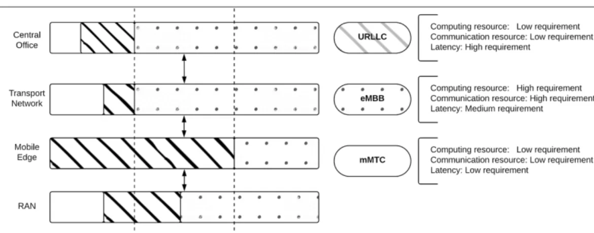
Figure 1 shows an illustrative example in which the MEC architecture supports three dif- ferent 5G service types (i.e., URLLC, eMBB, and mMTC) simultaneously. URLLC has low comput- ing resource and bandwidth requirements, but needs ultra-low latency. Consequently, most of the computing resources are allocated from the mobile edge, while most of the network resources are provided by the RAN. eMBB has large com- puting resource and bandwidth demands. Thus, its resource requirements are satisfied mainly by the central office and transport network. mMTC likewise requires high bandwidth, but has a more relaxed latency constraint. As a result, its resource requirements are satisfied mainly by the transport network, RAN and central office. Notably, slicing not only facilitates sharing of the MEC resources among multi-tenants, but also enables flexibility and scalability. For example, for a mMTC service such as smart kilowatt-hour meter information col- lection, it may be necessary to run the service only several times a year, but to support massive com- munications between hundreds or even thousands of meters each time. In such a case, slicing pro- vides the means to allocate the MEC computing and transport resources to the service only at the moment required, thereby enabling these resourc- es to be assigned to other tenants at other times.
In other words, E2E slicing has significant potential for realizing the full capabilities of 5G technology.
However, implementing E2E slicing in real-world 5G networks poses a major challenge, as discussed later.
nvF mAno: c oncept And o pen s ource I mplementAtIon
In implementing E2E slicing, Network Functions Virtualization (NFV — ETSI GS NFV-EVE 001) plays a key role in virtualizing the functions in the net- work nodes into building blocks called Virtual Network Functions (VNFs) that can be connect- ed, or chained together, to create services. The VNFs are usually orchestrated using the NFV Management and Orchestration (NFV MANO
— ETSI GS NFV-MAN 001) framework proposed by ETSI. In particular, E2E slicing uses MANO to
Slicing is a key technol- ogy in 5G networks for
enabling the realization of logical networks/
partitions with appro- priate isolation, scal- ability and flexibility of resource allocation.
According to the Next Generation Mobile Network (NGMN) Alliance, slicing makes possible the realization of multiple logical net- works for multi-tenants
on a single shared physical infrastructure.
facilitate the deployment and connection of mul- tiple services which are decoupled from dedicat- ed physical devices and moved to instances such as virtual machines (VMs) or containers instead.
The NFV MANO architecture consists of three functional blocks: the NFV Orchestrator (NFVO), the VNF Manager, and the Virtualized Infrastruc- ture Manager (VIM). NFVO communicates with multiple VNF managers to monitor the status of the shared physical infrastructure and determine whether additional resources are available for deployment. The mapping of the logical resources of the VNFs to the shared physical infrastructure is maintained by the VIM. While various open source NFVOs are available. Tacker (https://wiki.
openstack.org/wiki/Tacker) is one of the most commonly used since it integrates seamlessly with
Openstack (https://www.openstack.org/), which is one of the leading open source VNF managers and VIMs.
r elAted W orks
The authors in [1] applied E2E slicing to a Soft- ware-Defined Network (SDN)-based solution for next generation mobile networks. How- ever, the problem of sharing the RAN among multiple mobile users was not addressed.
Accordingly, the authors in [2] presented an approach for orchestrating the network resources across both the transport layer in the MEC architecture and the RAN layer. The studies in [3–4] also proposed methods for facilitating resource sharing in 5G mobile networks. However, the proposed methods FIGURE 1. Typical service types as slices in MEC architecture.
TABLE 1. Comparison of present method and previous proposals.
Papers Proposed Network/server
slicing (R/E/T/C)
Number of computing
resource tiers Implementation
SDN Based Next Generation Mobile Network with Service Slicing and Trials [1]
• Concept
• Model
• Algorithm
Network 0/0/T/0
0
No Multi-Domain Orchestration across RAN and Transport for 5G [2] • Concept
Network R/0/T/0 Multi-Tenant Slicing for Spectrum Management on the Road to 5G [3] • Architecture
Network Slicing to Enable Scalability and Flexibility in 5G Mobile Networks [4] • Architecture Network Slices toward 5G Communications — Slicing the LTE Network [5]
• Architecture
Both 0/0/T/C
1 Network Slicing for 5G-Challenges and Opportunities [6]
Network Slicing Based 5G and Future Mobile Networks-Mobility, Resource Management, and Challenges [7]
• Architecture
• Workflow An end-to-end network slicing framework for 5G wireless communication systems [8] • Concept
Both R/0/T/C Toward 5G Network Slicing over Multiple-Domains [9] • Architecture
• Workflow
Network Store — Exploring Slicing in Future 5G Networks [10] • Architecture Both
R/0/T/C 1
Multi-tenant 5G Network Slicing Architecture with Dynamic Deployment of Virtualized Yes Tenant Management and Orchestration (MANO) Instances [11]
• Architecture
• Workflow
Both 0/E/T/C
2
Proposed solution (JECRS) • Architecture
• Workflow
Both R/E/T/C
considered only the network resources. To address this problem, the authors in [5–9] con- sidered both the network resources and the computing resources. However, the methods in [5–7] ignored the RAN resources, while that in [8] provided only a simple treatment of the RAN resource. The authors in [9] provid- ed a more robust and complete architecture for full E2E (Cloud-to-RAN) slicing in 5G net- works. However, the problem of meeting the stringent latency requirements of 5G services such as URLLC was not properly addressed.
The authors in [10] and [11] presented sim- ple proof-of-concepts for E2E slicing in 5G networks, but failed to consider the edge and RAN resources, respectively. Table 1 compares the existing proposals for resource slicing in next-generation 5G mobile networks with the method proposed in the present study. As shown, the present method is the only method to consider server slicing and network slicing within the full two-tier MEC architecture. (Note that R, E, T, and C denote RAN, Edge, Trans- port network and Central office, respectively, and 0 indicates that slicing is not applied in the respective layer.) Furthermore, the proposed method is the only method to perform experi- mental demonstrations on a real testbed.
p roblem d escrIptIon
5G services generally have different connection traffic, and latency requirements (Fig. 1). More- over, MEC architectures are often required to support multiple tenants (with different 5G ser- vices) simultaneously. Accordingly, as described earlier, the present study proposes an E2E SaaS framework designated as JECRS, in which the computing and communication resources of the 2-tier MEC architecture are sliced and assigned to the tenants in accordance with their particular service demands (Fig. 2). Notably, the high-level resource requirements of the tenants are mapped dynamically to the computing and communica- tion levels of the MEC infrastructure in such a way as to satisfy the specific needs of each tenant while simultaneously maximizing the overall utili- zation efficiency of the MEC resources.
Implementing such an E2E slicing framework raises several key challenges, including:
• Orchestrating computing and communication resources in the 2-tier MEC architecture.
• Translating the capability requirements of the tenants (e.g., the latency requirements and number of served users) to the correspond- ing capacity (e.g., number of instructions per second and bytes per second) and resource requirements.
• Implementing slicing in the RAN layer.
• Supporting both time-based and event-base ser- vices in an efficient and effective manner.
p roposed s lIcer And 2-t Ier I nFrAstructure J oInt e dge And c entrAl r esource s lIcer (Jecrs)
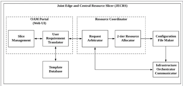
As shown in Fig. 3, the JECRS framework com- prises five key elements: an Operations, Admin- istration, and Maintenance (OAM) portal, a resource coordinator, a template database, a configuration file maker and an infrastructure orchestrator communicator. The OAM portal is
implemented as a web user interface (UI) and comprises two modules, namely a slice manage- ment module and a user requirement translator module. The former module enables the tenants to monitor the status of their slices and perform create/delete/modify tasks (e.g., scaling in/out services) as required. The latter module pro- vides the tenants with a set of tools to specify the capability requirements of their services. The module is interfaced with a database contain- ing a set of default mappings (templates), which are collected by translation history, between the capabilities of common 5G services, such as a latency constraint and a number of users, and the capacity of required resources in the MEC archi- tecture. Having specified their capability require- ments, the user requirement translator searches for an appropriate baseline configuration in the database. If no suitable template exists, the mod- ule translates the tenant’s service request into the corresponding capacity requirement and adds the mapping to the database. Having deter- mined an appropriate mapping, the request arbitrator in the resource coordinator considers whether or not the request can be accommo- dated based on the free resource information provided by the infrastructure orchestrator com- municator and the Service-level Agreements (SLAs) of the tenants. If the request is accept- ed, the 2-tier resource allocator determines the resources to be provided by each tier of the MEC infrastructure. In allocating the resources, the resource allocator chooses one of several pre-configured settings of a resource separation ratio, where this ratio determines the proportion of traffic to be handled by the central office and edge, respectively. The resource allocation result is passed to the configuration file maker, which creates a corresponding network service descrip- tor (NSD) with a format dynamically determined by the infrastructure orchestrator. The NSD is then transferred via the infrastructure orches- trator communicator to the orchestrator (e.g., Tacker, OpenMANO , or Cloudify ). On receipt of this NSD, the orchestrator deploys the corre- FIGURE 2. E2E slicing concept.
sponding slice to the tenant such that they can build their service.
2-t Ier I nFrAstructure
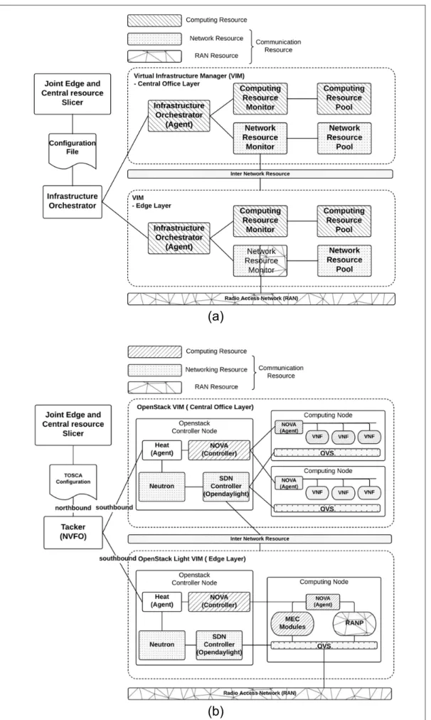
Figure 4 illustrates the interface between the proposed JECRS framework and the 2-tier MEC architecture. As shown in Fig. 4a, the resource orchestrator of the MEC architecture connects to two separate VIMs, where each VIM manages the computing and communication resources of the respective tier. In both tiers, the comput- ing resources are monitored continuously and their status regularly reported to the resource orchestrator agent of the tier. The agents then report this information back to the resource orchestrator to facilitate the JECRS procedure.
Regarding the communication resources, the upper-tier controls both the transport network between the two tiers and the intra network in the central office. Similarly, the lower-tier con- trols the intra network in the mobile edge and the RAN between the mobile edge and the user equipment. For both tiers, the communication resources are controlled by a SDN controller within the respective VIM. The controllers peri- odically report the network resource status to the resource orchestrator agents, which then forward this information to the main resource orchestrator of the MEC architecture. On receipt of a NSD from the JECRS framework, the orches- trator passes the logical resource allocation to the VIMs, which then map this information to the physical resource pools in order to set up a slice for the corresponding service.
I mplementAtIon WIth o pen s ource s oFtWAre
The NFVO of the 2-tier infrastructure was implemented using Tacker (Fig. 4b). More- over, the VIMs in the upper and lower tiers of the architecture were implemented using OpenStack, while the south-bound commu- nications between the NFVO and OpenStack were handled using heat agents (https://
wiki.openstack.org/wiki/Heat). The comput- ing resources were controlled using NOVA, a built-in element in OpenStack. The network resources were controlled by a SDN controller, namely OpenDaylight (ver. Oxygen) cooperat- ed with Neutron (https://wiki.openstack.org/
wiki/Neutron). OpenDaylight controlled the transport inter-network between the two tiers and the intra-network in the upper tier using Open vSwitch (OVS v2.8.4 — https://www.
openvswitch.org/). Neutron managed the intra network of the mobile edge based on the OVS of the lower tier and cooperated with a RAN proxy (RANP) [12], which a virtual Mobility Management Entity and multiple virtual base station modules are set up inside to process the control plane and then analyze the Non-access Stratum (NAS) message and identify the oper- ator of each user equipment. As for the data plane, a Tunnel Switching module processes incoming GTP data packets, and forwards them to the correct slice, to control the RAN. Final- ly, the north-bound communications between Tacker and the JECRS framework were handled using TOSCA (Topology and Orchestration Specification for Cloud Applications — https://
www.oasis-open.org/committees/tc_home.
php?wg_abbrev=tosca).
n umerIcAl r esults
t estbed d escrIptIon
An emulation platform was constructed consist- ing of a Frequency-Division Duplexing (FDD) LTE small cell supporting Multiple-Input Multi- ple-Output; a server equipped with an Intel Xeon CPU and 32G RAM as a cloud with Openstack (v3.13.0) and Tacker (v0.10.0); and a PC with an Intel i7 CPU and 4G RAM as the edge running Openstack (v3.13.0) within light-weight contain- ers. A CAT.4 dongle was attached to a com- mercial evolved node B powered by Wistron NeWeb Corporation (WNC) via an air interface to serve as the UE. All of the network equip- ment supported gigabit Ethernet. Three pseu- do tenant services were implemented, namely Pyvit (v0.2.1) to simulate the behavior of V2X traffic for URLLC; Mosquitto (v3.1) to simulate the behavior of mMTC based on the MQTT pro- tocol; and VLC (v2.2.2) to simulate the behav- ior of eMBB. NextEPC (v0.3.8) was used as the core network for all three services. For each service, given a resource request from the ten- ants, Perf, a benchmark testing application, was used to determine the corresponding computing FIGURE 3. JECRS framework.
Regarding the com- munication resources, the upper tier controls both the transport network between the two tiers and the intra network in the central office. Similarly, the lower tier controls the intra network in the mobile edge and the RAN between the mobile edge and the user equipment. For both tiers, the commu- nication resources are controlled by a SDN controller within the respective VIM.
FIGURE 4. Overview of 2-tier MEC infrastructure: a) 2-tier MEC infrastructure with computing and commu- nication resources; b) 2-tier infrastructure implementation with open sources.
(a)
(b)
The controllers peri- odically report the
network resource status to the resource orchestrator agents, which then forward this information to the main resource orchestrator of the MEC architec-
ture. On receipt of a NSD from the JECRS framework, the orches- trator passes the logical
resource allocation to the VIMs, which then map this information to the physical resource pools in order to set up a slice for the corre-
sponding service.
resource requirement in mips, while the network resource requirement in bps was established using iftop. A VM/container was then created and tested by the Phoronix Test Suite (v7.8.0) to check the availability of merely sufficient com- puting and communication resources. Given merely sufficient resources, the proposed slicer created a deployment configuration as a TOSCA file. The file was then passed to Tacker to set up the requested service in Openstack.
e xperIments
Isolation Effect of Slicing: The slicing isolation effect ratio was defined as
RservicetypeI = AservicetypeRN
ReqservicetypeRN + AservicetypeE
ReqservicetypeE
⎛
⎝⎜
+ AservicetypeTN
ReqservicetypeTN + AservicetypeC
ReqservicetypeC
⎞
⎠⎟ 4, (1) where AResource servicetype and ReqservicetypeResource denote the allo- cated slice resources in each tier and the required slice resources, respectively. Note that the index
“Resource” refers to the RAN (RN), Edge (E), Transport network (TN), or Central office (C) resources, while “servicetype” refers to URLLC, mMTC or eMBB. In Eq. 1, a value of R1 servicetype
greater than 1 indicates that more resources are allocated to the service than required. Converse- ly, a value of R1 servicetype less than 1 indicates that the slice resources are less than those required.
Finally, a value of R1 servicetype = 1 represents the outcome, in which the resources assigned to the tenant are just merely sufficient to support the required service.
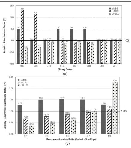
Figure 5a shows the results obtained for the iso- lation effectiveness ratio given the simultaneous deployment of the three different services and var- ious slicing scenarios. Note that the latency issue is not considered here. In other words, the edge resource (E) is not considered,
AservicetypeE
ReqservicetypeE =1
The lower-bound resource requirements (ReqResource
servicetype) for each service type were deter- mined from Perf and iftop to be as follows: one- core CPU, 4 Mb/s and 5 Mb/s of downlink in the RAN and transport network, respectively, for eMBB streaming; one-core CPU, 6 Mb/s and 8 Mb/s of uplink in the RAN and transport net- work, respectively, for mMTC IoT; and one-core CPU, 25 Mb/s and 28 Mb/s of uplink in the RAN and transport network, respectively, for URLLC V2X. In performing the experiments, only one ser- vice of each type was enabled at the same time.
The results presented in Fig. 5a show that eMBB always receives more resources than required when the resources of the central office are not included in the slice. VLC is a streaming application, and hence requires a large amount of computing resource to perform video decoding.
Consequently, it tends to consume any free com- puting resources within the MEC architecture. As a result, neither RURLLCI nor RmMTCI reaches a value of 1 when slicing is confined to “0TR.” However, streaming requires relatively low network resourc- es (i.e., for downlink only). Therefore, RURLLCI and RmMTCI both have a value close to 1 when slicing is confined to the network transport layer (“0T0”).
URLLC and mMTC both require uplink resources, and hence compete with one another for network resources when the RAN or transport network is not included in the slice. However, mMTC consis- tently gains more network resources than URLLC since the URLLC session is closed as soon as data transfer is completed, and the resources which are released as a result are immediately con- sumed by mMTC. When just one of the network tiers is considered in the slicing process (e.g., C0R) the resource isolation issue between URLLC and mMTC is almost solved. However, RURLLCI is still slightly lower than 1 in the “C0R” and “CT0”
slicing scenarios. In other words, a minor resource isolation issue still persists.
Overall, the results presented in Fig. 5a show that a significant imbalance exists between the resources allocated to the three services in the absence of slicing due to inherent differences in their behaviors and SLA requirements. In particular, some of the applications receive more resources than they require (i.e., eMBB and mMTC), while others fail to receive merely sufficient resources (i.e., URLLC). In other words, to guarantee the behavior and SLA requirements of the three service types, full E2E slicing is required in order to proper- FIGURE 5. Experimental results: a) isolation effectiveness of slicing for three
tenant services under different slicing scenarios (note that R, T, and C denote RAN, transport network and central office, respectively, and 0 indicates that slicing is not applied in the respective layer); b) latency sat- isfaction for three tenant services under different central-to-edge resource allocation ratios.
(a)
(b)
ly isolate the computing and network resources in each tier.
l Atency m onItorIng WIth d IFFerent c entrAl - to -e dge r esource A llocAtIon r AtIos
The slicing latency requirement satisfaction ratio was defined as
RservicetypeL LservicetypeReq
LservicetypeM ,
(2)
where LReq servicetype is the required latency of the tenant service and LM servicetype is the actual latency of the service after the slice is deployed. From Eq. 2, a value of Rservicetype L greater than 1 indicates that the actual latency surpasses that required by the service. By contrast, a value of RservicetypeL
less than 1 indicates that the allocated resources are insufficient to meet the latency requirements.
Finally, a value of 1 implies that the resources deployed in the slice are just merely sufficient to meet the latency requirements of the service.
Figure 5b shows the experimental results obtained for the latency requirement satisfaction ratio of the three services given different cental- to-edge resource allocation ratios. In performing the experiments, the latency requirements were set as follows: 10 s for eMBB streaming [13]; 100 ms for mMTC IoT [14]; and 25 ms for URLLC V2X [15]. Moreover, the delay between the cen- tral office and the edge was fixed as 60 ms for every service. The experiments emulated 10 cli- ents, each of which requested a video (eMBB), created 1000 connections and each connection sent 100 messages (mMTC IoT) and updated a video (total 10000 frames) to the server (URLLC).
As shown in Fig. 5b, the latency requirement sat- isfaction ratio for the eMBB service (i.e., RL eMBB) has an inverted U-shape tendency as the relative amount of resource provided by the edge increas- es. Consequently, the latency satisfaction ratio (1.52) is obtained when the resources are provided equally by the central office and edge, respectively.
The results imply that if most of the eMBB traffic is handled by the same tier, the processing time (i.e., the latency) increases. However, eMBB has a fairly loose latency constraint (10 s). Consequently, the latency requirement can be satisfied using all considered values of the central-to-edge resource allocation ratio. In practice, therefore, a resource allocation ratio of 9:1 is chosen as the solution in order to conserve the relatively rarer resources of the edge. Observing the results presented in Fig.
5b for RmMTCL and RLURLLC, it is seen that URLLC is more sensitive to the resource allocation ratio than mMTC. However, both applications require more than 70 percent of the needed computing resourc- es to be provided by the edge in order to satis- fy their tighter latency requirements. Overall, the results suggest a central-to-edge resource allocation ratio of 1:9 for the mMTC application (latency 100 ms) and 3:7 for the URLLC application (latency 25 ms). Interestingly, the mMTC application requires greater edge resources than the URLLC applica- tion despite having a relatively more relaxed laten- cy constraint. A further analysis revealed that this apparent anomaly can be attributed to the need of the mMTC application to collect and process a huge amount of data in a relatively shorter time than the URLLC application.
In general, the results presented in Fig. 5b con- firm that the resource allocation ratio has a signif- icant effect on the latency of the tenant services.
Thus, having established the overall slice capacity requirements for each service, a further evaluation process is required to determine the allocation of the resources between the two tiers of the MEC architecture.
c onclusIons And F uture W ork
This study has proposed a Joint Edge and Central Resource Slicer (JECRS) framework for End-to- End Slicing as a Service (E2E SaaS) in MEC envi- ronments. The framework considers a two-tier MEC architecture consisting of the central office and transport network in the upper tier and the edge and a RAN in the lower tier. The effective- ness of the proposed framework in allocating the computing and communication resources of the MEC architecture has been demonstrated using an experimental testbed constructed using open source software. The experiments have consid- ered three typical 5G services, namely, URLLC, mMTC, and eMBB, where these services are distinguished by different resource and laten- cy requirements. The experimental results have shown that the proposed framework provides an effective means of mapping the high-level capabil- ity requirements of the tenants to the MEC archi- tecture resources and assigning these resources to a slice on which the tenants can build their sys- tems. Importantly, the E2E slicing process isolates the computing and communication requirements of the tenants within each layer of the 2-tier structure (slicing isolation effect ratio equals 1) such that each service receives the resources it needs to satisfy its particular resource and latency requirements and ensures that computing and communication resources of the deployed slices are merely sufficient to meet the latency require- ments of the tenants. Moreover, the results sug- gest a central-to-edge resource allocation ratio of 9:1, 3:7, and 1:9 for the eMBB, URLLC, mMTC applications, respectively. However, the results would be affected by different QoS requirements and incoming traffic of the selected service. Also, the capacity of infrastructure would influence the results.
The contributions of this study can be summa- rized as follows:
• The E2E slicing framework considers both com- munication and computing resources in the full 2-tier MEC architecture.
• The JECRS mechanism provides the ability to translate the high-level requirements of the tenants to specific resource requirements in a seamless and automatic manner.
• The proposed framework provides the automat- ic support of both time-based and event-based services.
• The framework has been demonstrated experi- mentally using open source tools.
The JECRS framework has several limitations which should be addressed in future studies. For example, a more flexible algorithm is required to translate the high-level requirements of the ten- ants to specific resource requirements of the MEC architecture rather than the present simple map- ping solution. Similarly, an improved algorithm with optimization is required to support the NFVO in
The mMTC application requires greater edge resources than the URLLC application despite having a rel- atively more relaxed
latency constraint.
A further analysis revealed that this apparent anomaly can be attributed to the need of the mMTC application to collect and process a huge amount of data in a relatively shorter time than the URLLC application.
splitting the tenants’ resource and traffic require- ments between the upper and lower tiers of the MEC architecture. Finally, more comprehensive experiments are required to evaluate the perfor- mance of the JECRS framework in realistic 5G ser- vice environments.
r eFerence
[1] X. Xu et al., “SDN Based Next Generation Mobile Network with Service Slicing and Trials,” China Commun., vol. 11, no.
2, Feb. 2014, pp. 65–77.
[2] A. Rostami et al., “Multi-Domain Orchestration across RAN and Transport for 5G,” Proc. 2016 ACM SIGCOMM Conf., Aug. 22–26, 2016, pp. 613–14.
[3] M. Vincenzi et al., “Multi-Tenant Slicing for Spectrum Man- agement on the Road to 5G,” IEEE Wireless Commun., vol.
24, no. 5, Oct. 2017, pp. 118–25.
[4] P. Rost et al., “Network Slicing to Enable Scalability and Flex- ibility in 5G Mobile Networks,” IEEE Commun. Mag., vol. 55, no. 5, May 2017, pp. 72–79.
[5] K. Katsalis et al., “Network Slices toward 5G Communica- tions: Slicing the LTE Network,” IEEE Commun. Mag., vol. 55, no. 8, Aug. 2017, pp. 146–54.
[6] X. Li et al., “Network Slicing for 5G: Challenges and Oppor- tunities,” IEEE Internet Computing, vol. 21, no. 5, Sept. 2017, pp. 20–27.
[7] H. Zhang et al., “Network Slicing Based 5G and Future Mobile Networks: Mobility, Resource Management, and Challenges,” IEEE Commun. Mag., vol. 55, no. 8, Aug.
2017pp. 138–145.
[8] Q. Li et al., “An End-to-End Network Slicing Framework for 5G Wireless Communication Systems,” Cornell University Library, Aug. 2016.
[9] A. Ibrahim et al., “Towards 5G Network Slicing over Mul- tiple Domains,” IEICE Trans. Commun., Special section on Network Virtualization, Network Softwarisation, and Fusion Platform of Computing and Networking. vol. 100B, no. 11, Nov. 2017.
[10] N. Nikaein et al., “Network Store: Exploring Slicing in Future 5G Networks,” Proc. 10th Int’l. Workshop on Mobility, Paris, France, Sep. 07-07, 2015, pp. 8–13.
[11] A. Mayoral et al., “Multi-Tenant 5G Network Slicing Archi- tecture with Dynamic Deployment of Virtualized Tenant Management and Orchestration (MANO) Instances,” Proc.
42nd European Conf. Optical Communication ECOC 2016, Sept. 18–22, 2016.
[12] Y. D. Lin et al., “Transparent RAN Sharing of 5G Small and Macro Cells,” IEEE Wireless Commun., vol. 24, no. 6, Dec.
2017, pp. 104–11.
[13] S. S. Krishnan and R. K. Sitaraman, “Video Stream Quality Impacts Viewer Behavior: Inferring Causality Using Quasi-Ex- perimental Designs,” IEEE/ACM Trans. Networking, vol. 21, no. 6, Dec. 2013, pp. 2001–14.
[14] P. Schulz et al., “Latency Critical IoT Applications in 5G:
Perspective on the Design of Radio Interface and Network Architecture,” IEEE Commun. Mag., vol. 55, no. 2, Feb.
2017, pp. 70–78.
[15] M. Boban et al., “Use Cases, Requirements, and Design Considerations for 5G V2X,” IEEE Vehicular Technology Mag., Dec. 2017.
b IogrAphIes
Hsu-Tung CHien (hsutung@cs.nctu.edu.tw) received his B.S. and M.S. degrees in computer science from Tung Hai University, Taiwan, and National Chiao Tung University (NCTU), Taiwan, in 2014 and 2017, respectively. He has been pursuing his Ph.D.
at NCTU since 2017. His research interests include wireless net- works, mobile networks, and protocol design. He is also part of an H2020 project in 5GPPP, 5G-CORAL, to develop edge and fog systems for 5G networks.
Ying-Dar Lin (ydlin@cs.nctu.edu.tw) is a Distinguished Professor of computer science at National Chiao Tung University (NCTU), Tai- wan. He received his Ph.D. in computer science from the Univer- sity of California at Los Angeles (UCLA) in 1993. He was a visiting scholar at Cisco Systems in San Jose during 2007-2008, CEO at Telecom Technology Center, Taiwan, during 2010-2011, and Vice President of National Applied Research Labs (NARLabs), Taiwan, during 2017-2018. Since 2002, he has been the founder and direc- tor of Network Benchmarking Lab (NBL, www.nbl.org.tw), which reviews network products with real traffic and automated tools, and has been an approved test lab of the Open Networking Founda- tion (ONF) since July 2014. He also co-founded L7 Networks Inc.
in 2002, later acquired by D-Link Corp, and O’Prueba Inc. in 2018.
His research interests include network security, wireless communi- cations, and network softwarization. His work on multi-hop cellular was the first along this line, and has been cited over 850 times and standardized into IEEE 802.11s, IEEE 802.15.5, IEEE 802.16j, and 3GPP LTE-Advanced. He is an IEEE Fellow (class of 2013), IEEE Distinguished Lecturer (20142017), ONF Research Associate, and he received the 2017 Research Excellence Award and K. T. Li Breakthrough Award. He has served or is serving on the editorial boards of several IEEE journals and magazines, and is the Editor- in-Chief of IEEE Communications Surveys and Tutorials (COMST).
He published a textbook, Computer Networks: An Open Source Approach (www.mhhe.com/lin), with Ren-Hung Hwang and Fred Baker (McGraw-Hill, 2011).
CHia-Lin Lai (Chia-LinLai@itri.org.tw) received her M.S. and Ph.D. degrees in 2008 and 2014 from National Cheng-Kung University, Tainan, Taiwan. She was working at ICL, ITRI. Her research interests include optical networks, integrated fiber-wire- less networks, next generation network architecture, and proto- col design. She is a delegate to 3GPP SA Working Group (WG) 2 and focuses on related SIDs and WIDs of 5G network topics currently running in 3GPP. She also is part of the H2020 proj- ect in 5GPPP; 5G-Crosshaul to develop the transport network architecture and algorithms for 5G networks, and holds several patents in the United States, Mainland China, and Taiwan.
CHein-Ting Wang (ctwang@cs.nctu.edu.tw) received his M.S. degree in communications engineering from National Chung Cheng Uni- versity (CCU), Taiwan in 2013. He is currently pursuing his Ph.D.
in computer science at National Chiao Tung University (NCTU).
His research interests include software-defined networking, network function virtualization, service chain placement, and resource slicing.
The JECRS framework has several limitations which should be addressed in future studies. For example, a more flexible algorithm is required to translate the high-level require- ments of the tenants to specific resource requirements of the MEC architecture rather than the present simple mapping solution.