ZX-E Series
Smart Sensors: Inductive Displacement Type
Operation Manual
Introduction
Thank you for purchasing an OMRON ZX-E-series Smart Sensor (Inductive Displacement Type). We hope you will fully utilize this product and its performance for many years to come.
This manual describes the functions, performance, and application
methods of a ZX-E Smart Sensor. To ensure safety, read this manual carefully before
using the Sensor. In addition, keep this manual in an easily accessible location
for quick reference when needed.
ÇÕ Ç¹ Ç ? Ç ë Ê 1 èÕ ëÊ 2 èÕ ëÊ 3 èÕ ëÊ 4 èÕ Pr ef ace Se ct io n 1 S ec ti on 2 S ect ion 3 S e cti on 4 S ec ti on 5 S e ct io n 6
AppendicesIndexPreface
Section 1
Section 2
Section 3
Section 4
Section 5
Section 6
Appendices
Index
Contents, Terms and Conditions Agreement,
Precautions for Safe Use/Correct Use, and How to Use this Manual
Features
Preparations for Measurement
Basic Operation
Main Applications and Setting Methods
Detailed Settings
Auxiliary Functions
Troubleshooting, Specifications, Characteristic Data (Reference Value), etc.
Operation Manual
Smart Sensors
Pr ef ace
Preface
ÇÕ Ç¹ Ç ? Ç ë Ê 1 èÕ ë Ê 2 èÕ ë Ê 3 èÕ ëÊ 4 èÕ Pr ef ace Se ct io n 1 S ec ti on 2 S ect ion 3 S e cti on 4 S ec ti on 5 S e ct io n 6
AppendicesIndexContents
Contents 3
Precautions for Safe Use 11
Precautions for Correct Use 12
How to Use This Manual 13
Section 1 Features 15
ZX-E Features 16
Section 2 Preparations for Measurement 23
Basic Configuration 24
Part Names and Functions 25
Installing the Amplifier Unit 28
Installing Sensor Heads 30
Connections 34
Wiring Output Cables 38
Confirming Warm-up Completion 41
Pr ef ace Co nte n ts
Section 3 Basic Operation 43
Flow of Operation 44
Basic Knowledge for Operation 46
Function Transition Charts 51
Adjusting Linearity 54
Section 4 Main Applications and Setting Methods 61
Detecting Bottom Deadpoint 62
Measuring Height 67
Measuring Eccentricity and Vibration 71
Measuring Thickness 74
Section 5 Detailed Settings 79
Setting Number of Samples to Average 80
Using Hold Functions 81
Comparing Measured Values (Previous Value Comparisons) 88
Changing Display Scales 90
Entering Threshold Values 97
Linear Output 103
Setting Judgement Output Timing (Timer) 112
Preface
ÇÕ Ç¹ Ç ? Ç ë Ê 1 èÕ ë Ê 2 èÕ ë Ê 3 èÕ ëÊ 4 èÕ Pr ef ace Se ct io n 1 S ec ti on 2 S ect ion 3 S e cti on 4 S ec ti on 5 S e ct io n 6
AppendicesIndexSection 6 Auxiliary Functions 115
Measuring with Multiple Amplifier Units 116
Changing the Number of Display Digits 123
Reversing the Display 124
Adjusting Display Brightness (ECO Display) 126
Using the Zero Reset Function 127
Key Lock Function 132
Initializing Settings Data 133
Appendices 135
Troubleshooting 136
Error Messages and Countermeasures 137
Q&A 138
Glossary 139
Specifications and Dimensions 140
Characteristic Data (Reference Value) 148
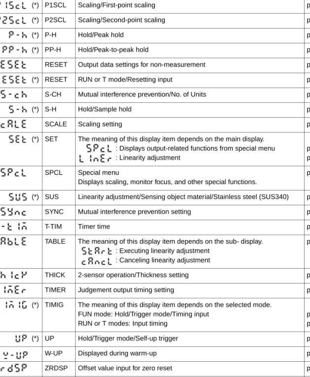
Quick Reference for Displays 157
Index 161
Revision History 165
Pr ef ace Co nte n ts
Pr ef ace PREFACE
Terms and Conditions Agreement
Warranty, Limitations of Liability
■ WARRANTY
●Exclusive Warranty
Omron’s exclusive warranty is that the Products will be free from defects in materials and workmanship for a period of twelve months from the date of sale by Omron (or such other period expressed in writing by Omron). Omron disclaims all other warranties, express or implied.
●Limitations
OMRON MAKES NO WARRANTY OR REPRESENTATION, EXPRESS OR IMPLIED, ABOUT NON-INFRINGEMENT, MERCHANTABILITY OR FITNESS FOR A PARTICULAR PURPOSE OF THE PRODUCTS. BUYER ACKNOWLEDGES THAT IT ALONE HAS DETERMINED THAT THE PRODUCTS WILL SUITABLY MEET THE REQUIREMENTS OF THEIR INTENDED USE.
Omron further disclaims all warranties and responsibility of any type for claims or expenses based on infringement by the Products or otherwise of any intellectual property right.
●Buyer Remedy
Omron’s sole obligation hereunder shall be, at Omron’s election, to (i) replace (in the form originally shipped with Buyer responsible for labor charges for removal or replacement thereof) the non-complying Product, (ii) repair the non-complying Product, or (iii) repay or credit Buyer an amount equal to the purchase price of the non-complying Product; provided that in no event shall Omron be responsible for warranty, repair, indemnity or any other claims or expenses regarding the Products unless Omron’s analysis confirms that the Products were properly handled, stored, installed and maintained and not subject to contamination, abuse, misuse or inappropriate modification. Return of any Products by Buyer must be approved in writing by Omron before shipment. Omron Companies shall not be liable for the suitability or unsuitability or the results from the use of Products in combination with any electrical or electronic components, circuits, system assemblies or any other materials or substances or environments. Any advice, recommendations or information given orally or in writing, are not to be construed as an amendment or addition to the above warranty.
See http://www.omron.com/global/ or contact your Omron representative for published
information.
Pr ef ace ■ Limitation on Liability; Etc
OMRON COMPANIES SHALL NOT BE LIABLE FOR SPECIAL, INDIRECT, INCIDENTAL, OR CONSEQUENTIAL DAMAGES, LOSS OF PROFITS OR PRODUCTION OR COMMERCIAL LOSS IN ANY WAY CONNECTED WITH THE PRODUCTS, WHETHER SUCH CLAIM IS BASED IN CONTRACT, WARRANTY, NEGLIGENCE OR STRICT LIABILITY.
Further, in no event shall liability of Omron Companies exceed the individual price of the Product on which liability is asserted.
Application Considerations
■ Suitability of Use
Omron Companies shall not be responsible for conformity with any standards, codes or regulations which apply to the combination of the Product in the Buyer’s application or use of the Product. At Buyer’s request, Omron will provide applicable third party certification documents identifying ratings and limitations of use which apply to the Product. This information by itself is not sufficient for a complete determination of the suitability of the Product in combination with the end product, machine, system, or other application or use.
Buyer shall be solely responsible for determining appropriateness of the particular Product with respect to Buyer’s application, product or system. Buyer shall take application responsibility in all cases.
NEVER USE THE PRODUCT FOR AN APPLICATION INVOLVING SERIOUS RISK TO LIFE OR PROPERTY WITHOUT ENSURING THAT THE SYSTEM AS A WHOLE HAS BEEN DESIGNED TO ADDRESS THE RISKS, AND THAT THE OMRON PRODUCT(S) IS PROPERLY RATED AND INSTALLED FOR THE INTENDED USE WITHIN THE OVERALL EQUIPMENT OR SYSTEM.
■ Programmable Products
Omron Companies shall not be responsible for the user’s programming of a programmable Product, or any consequence thereof.
Disclaimers
■ Performance Data
Data presented in Omron Company websites, catalogs and other materials is provided as a
guide for the user in determining suitability and does not constitute a warranty. It may represent
the result of Omron’s test conditions, and the user must correlate it to actual application
requirements. Actual performance is subject to the Omron’s Warranty and Limitations of
Liability.
Pr ef ace PREFACE
■ Change in Specifications
Product specifications and accessories may be changed at any time based on improvements and other reasons. It is our practice to change part numbers when published ratings or features are changed, or when significant construction changes are made. However, some specifications of the Product may be changed without any notice. When in doubt, special part numbers may be assigned to fix or establish key specifications for your application. Please consult with your Omron’s representative at any time to confirm actual specifications of purchased Product.
■ Errors and Omissions
Information presented by Omron Companies has been checked and is believed to be accurate;
however, no responsibility is assumed for clerical, typographical or proofreading errors or
omissions.
Pr ef ace
Preface Precautions for Safe U s e PREFACE
Precautions for Safe Use
Always observe the following precautions to ensure safety.
■ Environment
• Do not use the Smart Sensor in locations subject to explosive or flammable gases.
• To ensure safety in operation and maintenance, do not install the Smart Sensor near high-voltage equipment or power devices.
■ Power Supply and Wiring
• Do not impose voltages exceeding the rated voltage (12 to 24 VDC ±10%).
• When supplying power to the Sensor, make sure that the polarity of the power is cor- rect, and do not connect to an AC power supply.
• Do not short-circuit the load for the open collector output.
• Do not lay the power supply cable for the Smart Sensor together with high-voltage lines or power lines. Doing so, or placing them into the same duct, can cause induc- tion and lead to malfunction or damage.
• Always turn OFF the power supply before wiring and before connecting or disconnect- ing connectors.
■ Settings
• When setting the threshold value with the Smart Sensor connected to an external device, turn ON the Amplifier Unit's judgement output hold input to prevent the judgement from being output to the external device.
■ Applicable standards
• EN61326-1
• Electromagnetic environment: Industrial electromagnetic environment (EN/IEC 61326-1 Table 2)
• There may be cases that current output or voltage output fluctuate within ±3 times of resolution when a sensor is experienced electromagnetic interference.
■ Others
• The ZX-L-series Smart Sensors (Laser Type), ZX-W-series Smart Sensors (Micro- wave Type), and ZX-T-series Smart Sensors (High-precision Contact Type) are not compatible. Do not use ZX-L-series, ZX-W-series, or ZX-T-series Smart Sensors together with ZX-E-series Smart Sensors.
• Do not attempt to disassemble, repair, or modify the Smart Sensor.
• When disposing of the Smart Sensor, treat it as industrial waste.
Preface Precau tions for Correct Use
Precautions for Correct Use
Always observe the following precautions to prevent operation failures, malfunctions, and adverse effects on performance and equipment.
Smart Sensor Installation
■ Environment
Do not install the Smart Sensor in the following locations:
• Locations where the ambient temperature exceeds the rated temperature range
• Locations subject to rapid changes in temperature (causing condensation)
• Locations where the relative humidity exceeds the range of 35% to 85%
• Locations subject to corrosive or flammable gases
• Locations where dust, salt, or metallic powder accumulate on the Sensor
• Locations subject to direct vibration or impact
• Locations subject to direct sunlight
• Locations subject to exposure to water, oil, chemicals, etc.
• Locations subject to strong electromagnetic or electrical fields
• Locations subject to water vapor
Installation and Handling of Components
■ Power Supply and Wiring
• The total length of the Sensor cable or Amplifier cable must be 10 m or less.
Use a ZX-XC @A Extension Cable (order separately) if required to extend the cable from the Sensor. Use a shielded cable to extend the Amplifier cable. The shielded cable must be the same as that of the Amplifier cable.
• When using a commercially available switching regulator, ground the FG (frame ground) terminal.
• If the power supply line is subject to surges, connect a surge absorber that meets the conditions of the application environment.
• When connecting multiple Amplifier Units, connect the linear grounds of all the Ampli- fier Units.
■ Warm-up
After turning ON the power, allow the Smart Sensor to warm up for 30 minutes mini- mum prior to use. The circuitry is not stable immediately after turning the power ON, and the values gradually change until the Sensor is completely warmed up.
■ Maintenance and Inspection
• Always turn OFF the power supply before adjusting or removing the Sensor Head.
Pr ef ace Ho w to Use Th is M anua l PREFACE
How to Use This Manual
Page Format
Section Title Main Heading in a Section
Indicates page contents.
Outline
Provides an outline or gives a flowchart of the operation de- scribed under the main heading.
Sub-heading Index Label
Gives the section number and subject matter.
Function Outline and Suggestions
Operation
Indicates the operation to be performed next.
Display Area
Shows the display status after a step in an operation.
Keys and Switches
Provides an illustration of the keys or switches used during the operation.
Procedure and Additional Explanations
Information useful during the operation and reference pages are provided here with special marks to indicate the kind of information being provided.
* This page does not actually exist in this manual.
Section 3 Basic Operations
ZX-E Smart Sensor linearity is adjusted before shipment, however more accurate linearity can be obtained by adjusting linearity again for the actual sensing objects and operating environment.
Adjusting Linearity
This section describes how to set the sensing object material.
Selecting Sensing Object Material
To use the default linearity adjustment after changing materials, select the material and then select Adjust.
Changing to T Mode
Set the mode switch to T.
Set the switch to the threshold value to be set.
Press any Cursor Key.
The first digit of the threshold value displayed on the sub-display will flash and direct input will be enabled.
Change the threshold value with the Cursor Keys.
To cancel the selected setting, use the LEFT Key to move the cursor to the leftmost digit and press the LEFT Key again. he display will return to the current setting.
ZX-E Operation Manual
Pr ef ace Ho w to Use Th is M anua l
Notation
■ Menus
Items that appear on the digital displays are set in ALL-CAPS.
■ Procedures
The order for the procedures is indicated by numbered steps.
■ Visual Aids
Provides information on important operating procedures, gives advice on how to use functions, and highlights important performance information.
Indicates pages with relevant information.
Indicates useful information for when problems arise.
Se ct io n 1 FEATUR ES
Section 1 FEATURES
ZX-E Features 16
Se ct io n 1 ZX- E F eat ure s
FEATURES
ZX-E Features
The ZX-E Smart Sensor measures the distance between the Sensor Head and the sensing object.
Example: Detecting the Bottom Deadpoint on a Press Machine
Measurement detail
Sensing object
Distance
Measurement output
Judgement outputs
Se ct io n 1 ZX- E F eat ure s Section 1
FEATURES
Useful Notification Function
■ Warming Up Display
The display shows the warming-up status when the power is turned ON. This enables measurements to be started when the status has stabilized after warming up has been completed.
See page 41.
Many, Simple Functions
■ Measurement Ready at Power ON
The Smart Sensor can be used simply by installing and wiring it. Simply turn ON the power and it’s ready to operate.
The measurement distance is displayed on the Amplifier Unit.
Warming up in progress
Warming up completed Time lapsed after power up (min.)
Fluctuation of measured v alue Belo w specified resolution
The sub-display flashes
W-UP during warm-up.
Se ct io n 1 ZX- E F eat ure s
FEATURES
■ Simple Linearity Adjustment
Place the sensing object at specified distances and simply press the ENT Key to exe- cute precise linearity adjustment. Time-consuming offset and range adjustments are not required.
Precise adjustment is also possible for non-ferrous sensing objects.
p. 54
■ Simple Calculation Settings
Use a Calculating Unit to simply measure thickness and sum and difference calcula- tions between two measurements.
p. 116
Rated measurement distance
0% 50% 100%
Thickness
Calculating Unit
Se ct io n 1 ZX- E F eat ure s Section 1
FEATURES
Mutual Interference Prevention for Closely Mounted Sensor Heads
The Smart Sensor has a mutual interference prevention function which allows multiple Sensor Heads to be mounted close to each other. This function is supported for up to five Sensor Heads by using ZX-CAL2 Calculating Units.
p. 26 and p. 120
Compatibility between Sensor Heads and Amplifier Units
Amplifier Units do not need to be changed when Sensor Heads are changed for main- tenance or to switch to new products.
Calculating Units
Se ct io n 1 ZX- E F eat ure s
FEATURES
Extendable Sensor Head Cables
An extension cable with a maximum length of 8 m can be connected. The ZX-XC-A Extension Cable is required to extend the Sensor Head cable.
p. 24
Extension Cable
Up to 8 m
Se ct io n 1 ZX- E F eat ure s Section 1
FEATURES
Monitoring Measurement Status
■ Resolution Display for Sensing Object
The resolution can be displayed, allowing judgements to be made about detection mar- gins while viewing the resolution value.
p. 51
■ Confirm Measurement Status on a Personal Computer
Use an Interface Unit and Smart Monitor V2 to view measurement waveforms and log measurement data on a personal computer. This function is useful for making on-site measurement adjustments and for day-to-day quality control.
p. 24
Resolution
Resolution
Deviation to be detected
Smart Monitor V2
Interface Unit Amplifier Unit
Se ct io n 1 ZX- E F eat ure s
FEATURES
Sec tion 2 PREPAR A TIONS FOR MEAS UREMENT
Section 2
PREPARATIONS FOR MEASUREMENT
Basic Configuration 24
Part Names and Functions 25
Installing the Amplifier Unit 28
Installing Sensor Heads 30
Connections 34
Wiring Output Cables 38
Sec tion 2 Ba si c Conf ig urat io n
PREPARATIONS FOR MEASUREMENT
Basic Configuration
The basic configuration of the ZX-E-series Smart Sensors is shown below.
ZX-L-series Smart Sensors (Laser Type) and ZX-E-series Smart Sensors (Inductive Displacement Type) are not compatible. Do not use ZX-L-series and ZX-E-series Smart Sensors together.
Smart Monitor (software) ZX-SW11EV2 (Version 2.0 or later) Controls Amplifier Units from a personal computer and monitors measured values.
Personal computer
Interface Unit ZX-SF11
(Version 2.0 or later) Used when connecting a personal computer.
Basic Configuration
Sensor Heads ZX-ED@@T ZX-EM@@T ZX-EV@@T Sensor Heads detect the sensing objects.
Extension Cables ZX-XC1A (1 m) ZX-XC4A (4 m) ZX-XC8A (8 m) Used between Sensor Heads and Amplifier Units.
Amplifier Units ZX-EDA11 or ZX-EDA41 Process measure- ments and output
measurement results. Calculating Units ZX-CAL2
Used when connecting multiple Amplifier Units.
• Perform calculations.
• Prevent mutual interference
Power Supply 12 to 24 V DC (±10%)
p. 37
p. 25 p. 30
p. 35
Sec tion 2 Part Na m e s and F unct ions Section 2
PREPARATIONS FOR MEASUREMENT
Part Names and Functions
Amplifier Units
(1) The input cable connects the Sensor Head.
(2) The current/voltage switch selects either a current or voltage linear output.
Monitor focus settings are also required when switching the output. p. 103 (3) The connectors connect Calculation and Interface Units.
(4) The output cable connects to the power supply and external devices, such as sync sensors or programmable controllers.
(5) The Power ON indicator lights when the power is turned ON.
(6) The Zero Reset indicator lights when the zero reset function is enabled.
(7) The ENABLE indicator lights when the measurement result is within the measurement dis- tance.
(8) The HIGH indicator lights when the judgement result is HIGH.
(9) The PASS indicator lights when the judgement result is PASS.
(10) The LOW indicator lights when the judgement result is LOW.
(11) The main display shows measured values and function names.
(12) The sub-display shows additional information and function settings for measurements.
Reading Displays, p. 47
(13) The threshold switch selects whether to set (and display) the HIGH or LOW threshold.
(14) The mode switch selects the operating mode.
Switching Modes, p. 46 (15) The Control Keys set measurement conditions and make other settings.
Key Operations, p. 48
Display area (❋)
(1) Input cable
Controls (❋)
(4) Output cable
(3) Connectors (one on each side, two total)
(2) Current/voltage switch (back of Unit)
(8) HIGH indicator
(9) PASS indicator (10) LOW indicator
(11) Main display
(12) Sub-display (13) Threshold switch
(14) Mode switch (5) Power ON indicator
(6) Zero reset indicator
(15) Operating Keys (7) ENABLE indicator
❋ Details of Controls and Display Area
Current/voltage output selector
Voltage output
Current output
Sec tion 2 Part Na m e s and F unct ions
PREPARATIONS FOR MEASUREMENT
Sensor Heads
Calculating Units
Sensor head Preamplifier
Connector
Connects to Amplifier Unit.
Display (❋) Connectors (one on each side, two total) Connects to Amplifier Unit.
Connector indicators
Light when Calculating Unit is connected to Amplifier Units.
❋ Display Detail
Sec tion 2 Part Na m e s and F unct ions Section 2
PREPARATIONS FOR MEASUREMENT
Interface Units
(1) The communications connector connects the communications cable to the computer.
(2) The Amplifier Unit connector connects to the Amplifier Unit.
(3) The power supply indicator lights when the power is turned ON.
(4) BUSY: Lights during communications with the Smart Sensor.
ERR: Lights if an error occurs during communications with the Smart Sensor.
(5) BUSY: Lights during communications with the personal computer.
ERR: Lights if an error occurs during communications with the computer.
Display (❋)
(1) Communications Connector (2) Amplifier Unit Connector
(3) Power supply indicator
(4) Sensor communications indicators (BUSY and ERR)
(5) External terminal communications indicators (BUSY and ERR)
❋ Display Detail
Sec tion 2 In st al li ng t h e Ampli fie r Un it
PREPARATIONS FOR MEASUREMENT
Installing the Amplifier Unit
Amplifier Units can be easily mounted to 35-mm DIN Track.
■ Installation
Hook the connector end of the Amplifier Unit on the DIN Track and press in at the bot- tom until the Unit locks into place.
Always hook the connector end of the Amplifier Unit on the DIN Track first. Mounting strength may decrease if the output cable end is hooked on the DIN Track first.
DIN Track (order separately) PFP-100N (1 m)
PFP-50N (0. 5 m) PFP-100N2 (1 m)
End Plates (order separately) PFP-M
Hook on the connector end
Sec tion 2 In st al li ng t h e Ampli fie r Un it Section 2
PREPARATIONS FOR MEASUREMENT
■ Removal Method
Push the Amplifier Unit up and pull out from the connector end.
Sec tion 2 In st alling Sen s or Hea d s
PREPARATIONS FOR MEASUREMENT
Installing Sensor Heads
This section describes how to install Sensor Heads and Preamplifiers.
Fasten the connector so that it is not subjected to vibration or shock.
Sensor Heads
■ Installation
❚ ZX-ED@@T Sensor Heads (Non-threaded Type)
When using a set screw, tighten the screw to a torque of 0.2 N ⋅ m or less.
Mount the Sensor Head as shown in the following diagram.
❚ ZX-EM@@T Sensor Heads (Threaded Type)
The tightening torque for the threaded type (ZX-EM@@T) is shown in the following table.
When using the ZX-EM02HT, consider the thermal expansion caused by the rise in temperature of the sensing object, and make sure that the sensing object does not touch the sensing surface.
Even when operated within the specified temperature range, using in locations subject to extreme temperature fluctuations may result in deterioration of Sensor characteristics.
When using the ZX-EM02HT, make sure that the bending radius of the cable from the Sensor Head is 8 mm or greater .
Mounting Bracket (order separately) Y92E-F5R4 (for 5.4 mm dia.)
Set screw hole Model A
ZX-EDR5T 9 to 18
ZX-ED01T 9 to 18
ZX-ED02T 11 to 22
(Unit: mm)
Model Strength
(torque) ZX-EM02T
15 N·m ZX-EM07MT
ZX-EM02HT 5.9 N·m
Sec tion 2 In st alling Sen s or Hea d s Section 2
PREPARATIONS FOR MEASUREMENT
■ Installation Distance
Mount the Sensor Head so that the distance between the Sensor Head and the sens- ing object is approximately half of the measurement distance.
Use a ferrous sensing object larger than a standard sensing object. If a smaller-than-standard sensing object or a non-ferrous object is used, the predetermined characteristics may not be obtained.
Characteristic Data (Reference Value), p. 148
■ Influence of Surrounding Metal
Separate the Sensor Head from surrounding metals by at least the distances shown in the following diagram.
Sensing object: Ferrous object 18 × 18 mm or larger 0.5 mm
Example: ZX-ED01T Sensor Head Measurement distance: 0 to 1 mm
(Unit: mm)
Model Dia. A B
ZX-EDR5T 8 9
ZX-ED01T 10 9
ZX-ED02T 12 9
ZX-EM02T 12 9
ZX-EM07MT 55 20
ZX-EV04T 16×32 4.8
ZX-EM02HT 18 9
Dia.
Sec tion 2 In st alling Sen s or Hea d s
PREPARATIONS FOR MEASUREMENT
■ Mutual Interference
When using multiple Sensor Heads, separate each Sensor Head by the minimum dis- tances shown in the following diagram.
The distance between Sensor Heads can be further reduced when the Sensor Heads are side by side if the mutual interference prevention function is used.
Performing Calculations, p. 116
(Unit: mm)
Model A
B
Mutual Interference Prevention Function
Used Not used
ZX-EDR5T 5 3.1 20
ZX-ED01T 10 5.4 50
ZX-ED02T 20 8 50
ZX-EM02T 20 10 50
ZX-EM07MT 100 30 150
ZX-EV04T 80 14 50
ZX-EM02HT 20 12 50
• Face to face • Side by side
Sec tion 2 In st alling Sen s or Hea d s Section 2
PREPARATIONS FOR MEASUREMENT
Preamplifiers
■ Installation
Use the enclosed Preamplifier Mounting Bracket.
The Preamplifier can also be mounted to 35-mm DIN Track.
Use the ZX-XBE2 Preamplifier DIN Track Mounting Bracket (order separately) when mounting the Preamplifier to DIN Track.
1. Use M3 screws to fix the enclosed Preampli- fier mounting bracket.
2. Snap one end of the Preamplifier into the bracket.
3. Then snap the other end of the Preamplifier into the bracket.
■ Removal Method
Hold the center of the Preamplifier and lift.
Mounting Dimensions (Unit: mm)
Two, M3 holes
Sec tion 2 Co nne ction s
PREPARATIONS FOR MEASUREMENT
Connections
This section describes how to connect component parts of the Smart Sensor.
Turn OFF the power supply to the Amplifier Unit before connecting or removing components. The Smart Sen- sor may malfunction if components are connected or removed while the power is ON.
Sensor Heads
Do not touch the terminals inside the connector.
■ Connection Method
Push the Sensor Head connector into the Amplifier Unit connector until it locks.
■ Removal Method
When disconnecting the Sensor Head, hold the connector ring and the Amplifier Unit connector and pull them straight out.
Do not pull only on the connector ring, because the input cable of the Amplifier Unit may be dam- aged.
Connector ring
Sec tion 2 Co nne ction s Section 2
PREPARATIONS FOR MEASUREMENT
Calculating Units
Use a Calculating Unit to connect Amplifier Units when making calculations between Amplifier Units and to prevent mutual interference between Sensor Heads.
The number of Amplifier Units that can be joined depends on the functions being used.
Provide power to all connected Amplifier Units.
■ Connection Method
1. Open the connector covers on the Amplifier Units.
Open the connector covers by lifting and sliding them open.
2. Mount the Calculating Unit to the DIN Track.
3. Slide and connect the Calculating Unit to the Amplifier Unit connector.
4. Slide and connect the second Amplifier Unit to the Calculating Unit connector.
Function No. of Connectable Amplifier Units
Calculation 2
Mutual interference prevention 5
Sec tion 2 Co nne ction s
PREPARATIONS FOR MEASUREMENT
■ Channel Numbers of Amplifier Units
The following diagram shows the channel numbers when multiple Amplifier Units are
connected.
Sec tion 2 Co nne ction s Section 2
PREPARATIONS FOR MEASUREMENT
Interface Units
Use an Interface Unit to connect a personal computer to the Smart Sensor system.
■ Connection Method
1. Open the connector cover on the Amplifier Unit.
Open the connector cover by lifting and sliding it open.
2. Mount the Interface Unit to the DIN Track.
3. Slide and connect the Interface Unit to the Amplifier Unit connector.
Perform the above operation in the reverse order to remove Interface Units.
When multiple Amplifier Units are used, connect the Interface Unit to the Amplifier Unit with the highest channel number.
Sec tion 2 Wiring Outp ut Cables
PREPARATIONS FOR MEASUREMENT
Wiring Output Cables
The following diagram shows the wires in the output cable.
Wire the output cable correctly. Incorrect wiring may damage the Smart Sensor.
(Pay particular attention to prevent contact between the black wire (linear output) and other wires.)
Use the blue wire (0 V) for the power supply, and the shield wire (linear GND) together with the black wire (lin- ear output) for the linear output. Always ground the linear output even when the linear output is not used.
(1) A 12- to 24-VDC ( ± 10%) power supply is connected to the power supply terminals. When using an Amplifier Unit with a PNP output, the power supply terminal is also the common I/O terminal for all I/O except for the linear output.
Use a stabilized power supply separate from other devices and power systems for the Amplifier Unit, particularly when high resolution is required.
(2) The GND terminal is the 0-V power supply terminal. When using an Amplifier Unit with an NPN output, the GND terminal is also the common I/O terminal for all I/O except for the linear output.
(3) The HIGH judgement output outputs HIGH judgement results.
(4) The PASS judgement output outputs PASS judgement results.
(5) The LOW judgement output outputs LOW judgement results.
(6) The linear output outputs a current or voltage output in accordance with the measured value.
(7) The linear output GND terminal is the 0-V terminal for the linear output.
• Use the shield wire for the linear output. Do not use it in the same way as the blue wire (GND) for the power supply.
• Always connect the blue wire (GND) even when the linear output is not used.
(8) When the judgement output hold input is turned ON, the judgement outputs are held and not output to the external devices. Turn the judgement output hold input ON when setting thresh- old values.
When setting threshold values while connected to external devices, turn ON the Amplifier Unit’s judgement output hold input to prevent the outputs to external devices from changing.
(9) The zero reset input is used to execute and clear zero reset.
(10) The timing input is for signal input from external devices. Use it for hold function timing.
(1) Power supply (2) GND
(3) HIGH judgement output (4) PASS judgement output (5) LOW judgement output (6) Linear output (7) Linear output GND
(8) Judgement output hold input (9) Zero reset input
(10) Timing input (11) Reset input Brown
Blue White Green Gray Black Shield Pink Orange Purple Red
Sec tion 2 Wiring Outp ut Cables Section 2
PREPARATIONS FOR MEASUREMENT
I/O Circuit Diagrams
■ NPN Amplifier Unit
Load Load
Load
Current output: 300 Ω max.
Voltage output: 10 kΩ min.
Load Current output
(4 to 20 mA) Current/voltage output selector
Internal circuit
Brown 12 to 24 V DC
White
HIGH judgement output
Green PASS judgement output Gray LOW judgement output
12 to 24 V DC
Blue GND (0 V)
Pink Judgement output hold input Purple Timing input
Orange Zero reset input Red Reset input
Black Linear output
Shield Linear ground Voltage
output (±4 V) 100 Ω
Sec tion 2 Wiring Outp ut Cables
PREPARATIONS FOR MEASUREMENT
■ PNP Amplifier Unit
Load
Current output: 300 Ω max.
Voltage output: 10 kΩ min.
Current output (4 to 20 mA) Current/voltage output selector
Internal circuit
Brown 12 to 24 V DC
White HIGH judgement output
Green PASS judgement output Gray LOW judgement output
12 to 24 V DC
Blue GND (0 V)
Pink Judgement output hold input Purple Timing input
Orange Zero reset input Red Reset input
Black Linear output
Shield Linear ground Voltage
output (±4 V) 100 Ω
Load Load
Load
Sec tion 2 Co nfirming Warm- up Complet io n Section 2
PREPARATIONS FOR MEASUREMENT
Confirming Warm-up Completion
When the power is turned ON in RUN or T Mode, the sub-display will flash W-UP to show that the Sensor is warming up. Warm-up requires approximately 5 to 15 minutes. When warming up has been completed, the normal display will be shown.
Measurement operations can be performed while in warm-up display status, but the precision of measurements before warming up has been completed will be low. For high-precision measure- ments, wait until warming up has been completed.
SUB
Sec tion 2 Co nfirming Warm- up Complet io n
PREPARATIONS FOR MEASUREMENT
Sect ion 3 BAS IC OPER ATION
Section 3
BASIC OPERATION
Flow of Operation 44
Basic Knowledge for Operation 46
Switching Modes 46
Reading Displays 47
Key Operations 48
Setting Conditions 49
Inputting Numerals 50
Function Transition Charts 51
Adjusting Linearity 54
Selecting Sensing Object Material 54
Entering Adjustment Values 56
Executing Adjustment 58
Initializing Adjustment Settings 59
Sect ion 3 F low of Op era tion
BASIC OPERATION
Flow of Operation
Preparations for Measurement
Installation and Connection
Preparations for Measurement
Turn ON Power Supply
Reading Displays and Operating
Basic Knowledge for Operation
Setting Measurement Conditions to Executing Measurements
Adjusting Linearity
Adjusting Linearity
Making Settings for the Application
Detecting Bottom Deadpoint Measuring Height
Measuring Thickness Measuring Eccentricity and Vibration
Setting and Changing Measurement Data Setting Number of Samples to Average
Using Hold Functions Comparing Measured Values (Previous Value Comparison) Changing Display Scales
Setting Judgement Conditions
Entering Threshold Values
Setting Output Data
Linear Output
Setting Judgement Output Timing (Timer)
Correcting the Measurement Reference Point
If required
Using the Zero Reset Function
p. 54 p. 23
p. 46
p. 80 p. 81 p. 88 p. 90
p. 97
p. 112 p. 103
p. 127 p. 71
p. 62 p. 67
p. 74
Sect ion 3 F low of Op era tion Section 3
BASIC OPERATION
If Problems Occur
Abnormal Operation Troubleshooting
Unknown Terms Glossary
Error Messages Error Messages and Countermeasures
Meaning of Digital Display Quick Reference for Digital Displays
Applied Settings
Measuring with Multiple Amplifier Units
Performing Calculations Preventing Mutual Interference between
Saving Zero Reset Level
Setting Offset Values for Zero Reset
Additional Functions
Changing the Number of Display Digits
Using ECO Display Function
Reversing the Display
Key Lock Function
Initializing Settings Data
Changing Setttings
p. 136
p. 139
p. 120 p. 116
p. 129
p. 128
p. 123
p. 126
p. 124
p. 133 p. 132
p. 137
p. 157
Sect ion 3 Bas ic Kn owl edg e for O p er ati o n
BASIC OPERATION
Basic Knowledge for Operation
Switching Modes
The ZX-E has three modes. Use the Mode Switch on the Amplifier Unit to switch between modes. Switch to the desired mode before starting operation.
Function Transition Charts, p. 51
Mode Description
RUN Normal operation mode
T Mode for setting the threshold values FUN Mode for setting measurement conditions
Sect ion 3 Bas ic Kn owl edg e for O p er ati o n Section 3
BASIC OPERATION
Reading Displays
The data displayed on the main and sub-displays depends on the mode currently selected. When the power is first turned ON after shipment, RUN mode data is dis- played.
Function Transition Charts, p. 51
■ Alphabet Display Format
The alphabet appears on the main and sub-displays as shown in the following table.
Mode Main Display Sub-display
RUN Displays the measured value (the value after measurement conditions have been reflected.) For example, when the hold func- tion is set, the held value will be displayed.
Changes between displaying the present value (actual mea- sured value), threshold value, output value, and resolution in order when the Control Keys are pressed.
Threshold Value Display
Displays either the HIGH or LOW threshold value, depending on the position of the threshold switch.
The monitor focus setting determines whether the value is output as voltage or current.
Output Settings (Monitor Focus), p. 103
T Displays the measured value (the value after the measurement conditions have been reflected).
For example, when the hold func- tion is set, the held value will be displayed.
Displays the threshold value for the threshold being set.
Displays either the HIGH or LOW threshold value, depending on the position of the threshold switch.
FUN Displays the function names in order when the Control Keys are pressed.
Displays the setting for the function displayed on the main dis- play.
Main display
Sub-display
Sect ion 3 Bas ic Kn owl edg e for O p er ati o n
BASIC OPERATION
Key Operations
Use the Control Keys to change the display and set measurement conditions.
The mode currently selected determines the key functions.
Switching Modes, p. 46
Control Keys
Key Function
RUN Mode T Mode FUN Mode
Cursor Keys
LEFT Key
RIGHT Key
Changes sub-display content.
Used when selecting numeral digits.
Function changes depend- ing on setting.
• Switches function display.
• Selects numeral digit.
• Stops setting.
UP Key Performs timing input. Used when changing numerals.
Function changes depend- ing on setting.
• Switches between selections.
• Changes numerals.
DOWN Key Resets input.
ENT Key Performs zero reset. Function changes depend- ing on operation.
• Confirms threshold value.
• Executes teaching.
Confirms the set condition or value.
Sect ion 3 Bas ic Kn owl edg e for O p er ati o n Section 3
BASIC OPERATION
Setting Conditions
Display the target function on the main display and select the desired value from the sub-display to set measurement conditions.
This section uses the example of setting a peak hold as the hold condition to explain how to set measurement conditions.
Changing to FUN Mode and HOLD
1. Set the mode switch to FUN.
2. Use the LEFT and RIGHT Keys to display HOLD on the main display.
Setting Hold Conditions
3. Press either the UP or DOWN Key.
The present set value will flash on the sub-display.
4. Use the UP and DOWN Keys to select P-H.
Press either the LEFT or RIGHT Key to cancel the selected option. The display will return to the current set- ting (OFF in this example).
5. When you finish selecting the set value, press the ENT Key to confirm the setting.
The setting will be registered.
Sect ion 3 Bas ic Kn owl edg e for O p er ati o n
BASIC OPERATION
Inputting Numerals
This section describes how to input numeric values for threshold and output settings.
The example of direct input of the low threshold value will be used.
Changing the low threshold from 0.2000 to 0.1900
Changing to T Mode
1. Set the mode switch to T.
Setting Threshold Value
2. Set the switch to L.
The measured value will be displayed on the main display. The current setting will be displayed on the sub- display.
3. Press any Cursor Key.
The first digit on the sub-display will flash and direct input will be enabled.
4. Use the LEFT or RIGHT Key to move the cur- sor to the first decimal place.
5. Use the UP or Down Key to display 1.
6. Repeat steps 4 and 5 to move the cursor to the second decimal place and display 9.
To cancel the selected setting, use the LEFT Key to move the cursor to the leftmost digit and press the LEFT Key again. Alternatively, use the RIGHT Key to move to the rightmost digit and press the RIGHT Key again. The dis- play will return to the current setting (0.2000 in this exam- ple).
7. When you finish adjusting the numeric value, press the ENT Key to confirm the value.
The display will change from flashing to being lit continu-
Sect ion 3 F unct ion Tran sition Char ts Section 3
BASIC OPERATION
Function Transition Charts
Reading Transition Charts
The upper section is the main display and the lower section is the sub-display.
RUN Mode
The numerals shown in the above diagram are an example only. The actual display may be different.
Present Values and Measured Values
p. 139
T Mode
There is no function transition in T mode.
The numerals shown in the above diagram are an example only. The actual display may be different.
In RUN and T modes, the position of the threshold switch will determine whether the HIGH or LOW threshold will be displayed.
Main display Sub-display
Measured value (See note.) (The main display always shows the measured value.)
Present value (See note.)
Note: In FUN mode, the measured value and present value are displayed first.
Threshold value Output value Resolution
Measured value
Threshold value
p. 97
Threshold switch
Sect ion 3 F unct ion Tran sition Char ts
BASIC OPERATION
FUN Mode
Linearity adjustment
(See note 1.) Hysteresis Hold
Trigger mode
Special functions
Monitor focus Scaling
ECO mode Display reverse Number of samples
to average
Previous value comparison
Linear output correction
Limited number of display digits
Display during zero reset
Zero reset memory
Clamp value setting
Settings for non- measurement Mutual interfer-
ence prevention (See note 3.)
Note 1: Linearity adjustment is dis- played first when you enter FUN mode.
When CLOSE is selected, the special functions will not be displayed and the display will return to LINER.
Note 2: Previous value compari- son is displayed when hold is not set to OFF.
Note 3: Mutual interference prevention is displayed only on the CH1 Amplifier Unit.
(See note 2.)
p. 54 p. 80 p. 102
p. 81
p. 83
p. 88 p. 107 p. 103 p. 90
p. 123 p. 126 p. 124
p. 120 p. 127 p. 130
p. 110
Sect ion 3 F unct ion Tran sition Char ts Section 3
BASIC OPERATION
Note 4: When multiple Amplifier Units are con- nected, 2-sensor operation is displayed on all but the CH1 Amplifier Unit.
This symbol indicates that after the ENT Key has been pressed to confirm the selection, the LEFT and RIGHT Keys should be pressed to move through the menu.
Delay hold
Delay time
Timer
Special
2-sensor operation Sampling period
Self trigger level Self trigger hys- teresis width
Settings initialization
Thickness setting mode
Timer time setting
(See note 4.)
p. 86 p. 86 p. 86
p. 112
p. 83 p. 83
p. 116 p. 116
p. 133
p. 112
Sect ion 3 Adjus ting Linea rity
BASIC OPERATION
Adjusting Linearity
ZX-E Smart Sensor linearity is adjusted before shipment, however more accurate linearity can be obtained by adjusting linearity again for the actual sensing objects and operating environment.
Adjust linearity before setting measurement conditions. Linearity should also be adjusted again when Sensor Heads are replaced.
❚ Flow of Operation
Linearity
p. 139
Selecting Sensing Object Material
This section describes how to set the sensing object material.
Linearity According to Material
Characteristic Data (Reference Value), p. 148
To use the default linearity adjustment after changing materials, select the material and then perform Executing Adjustment.
Selecting Sensing Object Material
Entering Adjustment Values
Executing Adjustment
Selection Material FE (default) Iron
SUS Stainless steel (SUS304)
AL Aluminum
Sect ion 3 Adjus ting Linea rity Section 3
BASIC OPERATION
Changing to FUN Mode and LINER
1. Set the mode switch to FUN.
2. Use the LEFT or RIGHT Key to display LINER on the main display.
Setting Sensor Object Material
3. Press the ENT Key.
METAL will be displayed.
4. Press the UP or DOWN Key.
The sub-display will flash.
5. Use the UP or DOWN Key to select the mate- rial.
6. Press the ENT Key to confirm the selection.
The setting will be registered.
Sect ion 3 Adjus ting Linea rity
BASIC OPERATION
Entering Adjustment Values
Set the sensing object at the positions for 0%, 50%, and 100% of the rated measure- ment distance and register those measured values as the adjustment values.
Measurement distance, p. 143
Perform the registration in order, starting with 0%, then 50% and 100% of the measure- ment distance.
To simply replace the sensing object material and use the default linearity adjustment, skip this oper- ation and perform Executing Adjustment.
Entering Adjustment Value for 0% Position
1. Set the sensing object at the 0% position.
2. Use the LEFT and RIGHT Keys to display D000.
3. Press the ENT Key.
The sub-display will show OK and the adjustment value will be registered.
Press the ENT Key again to reinput the adjust- ment value.
Rated measurement distance
0% 50% 100%
0%
Rated measure- ment distance
Sect ion 3 Adjus ting Linea rity Section 3
BASIC OPERATION
Entering Adjustment Value for 50% Position
4. Move the sensing object to the 50% position.
5. Use the LEFT and RIGHT Keys to display D050.
6. Press the ENT Key.
The sub-display will show OK and the adjustment value will be registered.
Press the ENT Key again to reinput the adjust- ment value.
Entering Adjustment Value for 100% Position
7. Move the sensing object to the 100% posi- tion.
8. Use the LEFT or RIGHT Keys to display D100.
9. Press the ENT Key.
The sub-display will show OK and the adjustment value will be registered.
Press the ENT Key again to reinput the adjust- ment value.
Rated measure- ment distance 50%
Rated measure- ment distance
100%
Sect ion 3 Adjus ting Linea rity
BASIC OPERATION
Executing Adjustment
This section describes how to execute adjustment based on the settings made in steps and .
Executing Adjustment
1. Use the LEFT and RIGHT Keys to display TABLE on the main display and START on the sub-display.
2. Press the ENT Key.
Linear adjustment will be executed.
When the adjustment data has been registered, the sub- display will show OK.
If the sub-display shows ERRTB, there has been a mis- take in the settings. Check the material selected for the sensing object and the set positions and register the set- tings again.
■ Cancelling Adjustment
The adjustment settings will be cleared if the adjustment is cancelled.
1. Use the LEFT and RIGHT Keys to display TABLE on the main display and CANCL on the sub-display.
2. Press the ENT Key.
The settings for the current adjustment will be cancelled and the display will change to LINER.
OK
NG
Sect ion 3 Adjus ting Linea rity Section 3
BASIC OPERATION
Initializing Adjustment Settings
Initialize the linearity adjustment settings to return to the default settings.
This section describes how to initialize the linearity adjustment settings only. To initial- ize other settings, use the INIT function.
Initializing Settings Data, p. 133
Moving to FUN Mode and LINER
1. Set the mode switch to FUN.
2. Use the LEFT and RIGHT Keys to display LINER on the main display.
Initializing Settings
3. Press the ENT Key.
The display will show METAL.
4. Use the LEFT and RIGHT Keys to display LINIT.
5. Press and hold down the ENT Key.
One dash (−) at a time will appear on the sub-display.
6. Release the ENT Key once OK is displayed on the sub-display.
The adjustment settings have been initialized.
Sect ion 3 Adjus ting Linea rity
BASIC OPERATION
Section 4 MAIN A PPLICATIONS AND SETTING METHODS
Section 4
MAIN APPLICATIONS AND SETTING METHODS
Detecting Bottom Deadpoint 62
Measuring Height 67
Measuring Eccentricity and Vibration 71
Measuring Thickness 74
Section 4 Det ect in g Bo tt om De adpo in t
MAIN APPLICATIONS AND SETTING METHODS
Detecting Bottom Deadpoint
This section describes, as an example, how to detect the bottom deadpoint of a press machine.
When making settings while still connected to an external device, set the Amplifier Unit’s judgement output hold input to ON so that the output to the external device remains unchanged.
Adjust linearity before executing this operation.
Adjusting Linearity, p. 54
❚ Flow of Operation
Mounting Sensor to Press
Adjusting Detection Position
Setting Bottom Deadpoint Position Setting
Measurement Timing
Setting Tolerance Judgement Values
Section 4 Det ect in g Bo tt om De adpo in t Section 4
MAIN APPLICATIONS AND SETTING METHODS
Mounting Sensor to Press
Mount the Sensor Head and the sensing object to the press machine. Refer to the fol- lowing diagram for the required mounting jig.
Installing Sensor Heads, p. 30
Use a ferrous sensing object and one that is as large as or larger than the standard sensing object.
Sensing object, p. 143
Adjusting Detection Position
Adjust the position of the Sensor Head so that when the press machine is set at the bottom deadpoint position, the distance between the Sensor Head and the sensing object is about half of the measurement distance. Refer to the Amplifier Unit display while adjusting the Sensor Head position.
Measurement Distance, p. 143
Sensing objectSection 4 Det ect in g Bo tt om De adpo in t
MAIN APPLICATIONS AND SETTING METHODS
1. Put the press machine in inching mode and lower the stripper (or top mold) to the bottom deadpoint.
2. Adjust the position of the Sensor Head so that this position is at about half of the measure- ment distance.
The measured value will be displayed on the Amplifier Unit. Refer to this display while adjusting the Sensor Head.
Stripper or top mold Bottom mold
1/2 the measurement distance
Section 4 Det ect in g Bo tt om De adpo in t Section 4
MAIN APPLICATIONS AND SETTING METHODS
Setting Measurement Timing
The hold function is used to detect the bottom deadpoint.
To ignore bounding when measuring during press operation, specify a time delay from the timing signal to when sampling starts.
When the timing signal cannot be input from the device, set a self-down trigger.
Refer to Section 5 Detailed Settings for details on settings.
Using Hold Functions, p. 81
Measured value
Self-trigger level
The bottom value is held.
Timing input
Delay
time Sampling
period