Output Power Leveling of Wind Generation System Using Inertia for PM Synchronous Generator
Abdul Motin Howlader, Naomitsu Urasaki, Tomonobu Senjyu, Atsushi
Yona
Department of Electrical and Electronics Engineering, University of the Ryukyus, 1 Senbaru, Nishihara-cho,
Okinawa, Japan 903-0213, Email: b985542@tec.u-ryukyu.ac.jp.
Toshihisa Funabashi
Meidensha Corporation 36-2, Nihonbashi, Hakozaki-cho,
Chuo-ku, Tokyo 130-8515, Email: funabashi- t@mb.meidensha.co.jp
Ahmed Y. Saber
Department of Electrical and Computer Engineering,
Missouri University of Science & Technology, USA
Email: aysaber@ieee.org.
Abstract -- Wind energy conversion systems have become important in the research of renewable energy sources. This is not a small part due to the rapid advances in the size of wind generators as well as the development of power electronics and their applicability in wind energy extraction. However, wind energy has a drawback of having only 1/800 density as compared to that of water energy, and it does not remain constant and wind turbine output is proportional to the cube of wind speed, which causes the generated power of wind turbine generator (WTG) to fluctuate. In this paper, a technique is proposed for output power leveling of a wind generation system.
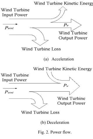
Wind turbine blades have large inertia compared to the inertia of generator. The inertia of the rotor behaves like an inductor in an electrical circuit. It helps smooth the wind turbine output power, stores energy during acceleration, and restores energy during deceleration. The effectiveness of output power leveling control is verified by simulations for the wind power generation system.
Index Terms-- Permanent magnet synchronous generator, inertia, MPPT, wind power leveling, wind turbine
I. INTRODUCTION
Electric power generation using non-conventional sources is receiving considerable attention throughout the world.
Wind energy is a significant and powerful resource. It is safe, clean, and abundant. Unlike conventional fuels, wind energy is a massive indigenous power source permanently available in virtually every nation of the world. It delivers the energy security benefits by avoiding fuel costs, long term fuel price risk, and the economic and supply risks that come with reliance on imported fuels and political dependence on other countries. However, wind energy has a drawback of having only 1/800 density as compared to that of water energy, and it is not constant and wind turbine output is proportional to the cube of wind speed, which causes the generated power of the wind turbine generator (WTG) to fluctuate [1]. How to smooth output power of wind generation system is important.
Because of this problem, various schemes have been reported in recent years. For example, using storage battery, superconducting magnetic energy storage (SMES) [2, 3], electric double layer capacitor (EDLC) [4,5], aqua electrolyze
with fuel cell [6,7], flywheel energy storage system (FESS), and back-up generator. However, high frequency charge and discharges affect the efficiency of the lead-acid battery thereby shortening its life. SMES and EDLC are very expensive. Aqua electrolyze with fuel cell system is very large. Back-up generator requires operational cost [8].
In this paper, a wind generation system output power leveling technique is proposed. It is realized by two events:
increase in wind turbine kinetic energy due to the acceleration of the turbine rotational speed as result of the rapid increase in wind speed, and discharge of wind turbine kinetic energy due to decrease in the wind turbine rotational speed when the wind velocity is dropped.
In the wind generation system, the permanent magnet synchronous generator (PMSG) is introduced because this configuration a gearbox is not needed. Therefore all the problems produced by the gearbox are avoided. The effectiveness of output power leveling control is verified by simulations for the wind power generation system.
II. WIND GENERATION SYSTEM
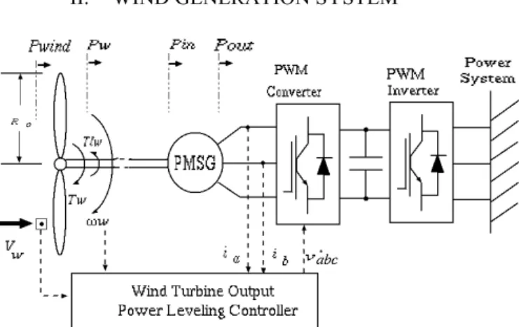
Fig. 1. Wind generation system configuration.
The configuration of the wind power generation system is shown in Fig. 1. The wind energy obtained from the wind
PEDS2009
(a) Acceleration
(b) Deceleration Fig. 2. Power flow.
turbine is sent to PMSG. The PMSG is controlled by the PWM converter and by the output power leveling controller.
If all the wind power is converted to mechanical power, the input power Pwind is expressed as
3 2
2 1
w o
wind
R V
P = ρπ
(1) where Ro is the wind turbine blade radius, Vw is the wind speed and ρ is air density. The wind turbine input torque Twindcan be described as
wind w
wind
P
T ω
= λ
2 3
2 1
w o
V ρπ R
=
(2) where ωw is the angular velocity of wind turbine and λ is the tip speed ratio, can be defined asw w
V R ω
λ =
0 . The wind turbine converts wind power into mechanical power Pw:p w o
w
R V C
P
2 32 1 ρπ
=
. (3) The power coefficient Cp is defined asγλ ζλ ξλ + +
=
3 2C
p where ξ, ζ, and γ are coefficients that are determined by size, form of blade, the number of blades and pitch angle of wind turbine blade. Wind turbineoutput torque is defined by
t w o
w
R V C
T
3 22 1 ρπ
=
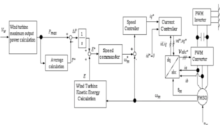
(4)Fig. 3. WTG power leveling control system.
where Ct is the torque coefficient defined as
. λ
p t
C = C
The wind turbine loss torque, Tf , serves as a convex function according to wind velocity and wind turbine rotor speed [9], it can be expressed as an approximation equation
2
.
2 1
2
0 w w w w
w wind f
K V
K V K
T T T
ω ω + +
=
−
=
(5)Here, the wind turbine loss coefficients K0, K1 and K2 are expressed as
) 1 2 (
1
0
0
= ρ SR − γ
K
(6)ζ ρ
021
2
1 SR
K = −
(7)ξ ρ
032
2
1 SR
K = −
(8) where S is the blade rotation area. The motion equation of the wind turbine is expressed aslw w w
w
T
dt J d
T = ω +
(9) where Jw is the wind turbine inertia and Tlw is the load torque which corresponds to the input torque of generator.Input power to the generator Pin is expressed as
m lw
in
T
P = − ω
(10)where ωm is the angular velocity of the generator. The motion equation of the generator is expressed as
m lw m m m
m
D T T
dt
J d ω + ω + =
(11) where Jm is the generator inertia, Dm is the damping coefficient and Tm is the generator electric torque. Output power of the generator Pout is expressed asm
.
m
out
T
P = ω
(12) III. OUTPUT POWER LEVELING CONTROL Wind generation system output power leveling is realized as a result of both charge and discharge of the kinetic energy in response to the wind speed. Charging occurs when thePEDS2009
Fig. 4. Control system.
wind turbine rotational speed accelerates as the wind speed increases, while discharge follows the deceleration of the wind turbine as the wind velocity decreases. Power flow is shown in Fig. 2. Wind generation system output leveling controller is shown in Fig. 3. First, maximum
Fig. 5. Circuit and phasor diagram of PMSG wind turbine output power, Pmx, is calculated from wind velocity. The wind turbine output, Pw, in a steady state is Pw=Twωw. The wind turbine output serves as the cubic function of wind turbine rotor speed ωw, which is described as
w w o
w f wind w
V K R
T P P
ω ρπ
ω
2
2
01
) (
⎟ ⎠
⎜ ⎞
⎝
⎛ −
=
−
=
3
.
2 2
1
V
w wK
wK ω − ω
−
(13) The optimal wind turbine rotor speed,ω
woptis obtained as the local maximum of the following equation due to dPw/dωw = 0( )
3 . 2 3 1
2
2 0 3 2
2 1 1
K
V K R K
V K V
K w w o w
opt w
⎟⎠
⎜ ⎞
⎝
⎛ −
− +
−
=
ρπ
ω (14)
Wind turbine maximum output power, Pmx is determined as
opt w opt
w w opt
w w o
opt w w mx
K V
K V
K R T P
3 2 2
1 2
2 0
1ρπ ω ω ω
ω
−
−
⎟⎠
⎜ ⎞
⎝
⎛ −
=
= (15)
Next, the charge difference between the maximum output power and the commanded output power (mean of maximum output power), ΔP, gives the wind turbine kinetic energy:
∫
−=
TT t
P
mxdt P
*T 1
(16)
where t denotes the present time and T is the integral time.
Wind turbine kinetic energy, E, is determined as
2 .
1
2w
J
wE = ω
(17) The wind turbine rotational speed command, ωw*, is determined from kinetic energy command, E*(sum ofdt
∫ Δ P
and E), asw
w
J
E
**
2
ω =
(18) The generator speed reference ωm* for the proposed method, is determined from gear ratio, Rn, as*
*
w n
m
R ω
ω =
(19) and for the MPPTopt w n
m
R ω
ω
*=
(20)IV. PERMANENT MAGNET SYNCHRONOUS
GENERATOR (PMSG) The system configuration of the proposed operation system is shown in Fig. 4. The wind generation system output power leveling control is configured using the proposed technique.
The synchronous generator can be electrically represented by a one-phase equivalent circuit as shown in Fig. 5. In power system analysis, the synchronous machine models are usually based on the assumption that the magnetic flux distribution in the rotor is approximately sinusoidal [10].
With this assumption, the flux can entirely be described by a vector and thus the internal voltage V induced in the stator winding by the permanent magnet flux ψPMcan be expressed as:
PM e PM
m
f
V | ω ψ 2 π ψ
| = =
(21) where fe is the electrical frequency. Notice that the internal voltage V depends on the electrical speed of the generator.Under load conditions, the stator current Is and the stator reactance in the stator winding produce a magnetic field of its own, which is superposed to the field generated by the permanent magnets. Thus, the voltage US at the stator terminal of PMSG corresponds to the voltage induced by the total magnetic field. Depending on the phase delay (load angle) between the internal voltage V and the stator voltage Us, the total magnetic field in the generator either increases or decreases as the current increases. Because of the fluxed
PEDS2009
excitation of PMSG, the converter has to provide or consume reactive power, and there-fore, the converter must be
oversized [11].
The equations of a PMSG can be expressed directly from the equations of a DC excited synchronous generator, with the simplification that PMSG does not have damper winding [10].
The steady-state voltage equations of the generator, expressed in the rotor-oriented dq-reference frame RRF, can be
expressed as follows:
sd sq m sd s sd
R i
u = − ω ψ + Ψ
(22)sq sd m sq s sq
R i
u = − ω ψ + Ψ
(23) with the stator flux components:PM sd d sd
= L i + Ψ
Ψ
(24)sq d sq
= L i
Ψ
(25) where uds and uqs are the terminal stator voltages, idsand iqs are the stator currents, Ld and Lq are the stator
Inductances in the dq-reference frame. In stability studies, the stator transients can be neglected. If the PMSG is assumed to be a round rotor machine, which is a reasonable
approximation for this type of generator [10], the electrical torque of the generator can be expressed in RRF with:
sq PM
m
p i
T = Ψ
2
3
(26)Furthermore, the power of the synchronous generator can be then expressed as:
[
sd sd sqsq]
gen
u i u i
P = +
2
3
(27)V. SIMULATION RESULTS
The effectiveness of the proposed method is demonstrated through simulation results. The system parameters used on the simulation are shown in Table (I) and (II). Output power leveling function, *Plevel, to evaluate the proposed method, are defined as [12]
) . (
0
*
dt
dt t
P
level= ∫
tdP
out (28) The *Plevel is the integral of absolute value of derivative of Pout. The fluctuation quantity of output power gets smaller by increasing *Plevel.TABLEI WIND TURBINE PARAMETERS.
Blade radius Ro= 1.26 m
Air density ρ =1.225 kg/m3
Gear ratio Rn=1
Wind turbine loss coefficients K0=3.8226 K1=-0.0323 K2=0.0024 Moment of inertia Jw=33 kg.m2
TABLEII
PMSYNCHRONOUSGENERATORPARAMETERS.
Rated capacity 3 kW
Number of poles P = 6
Stator resistance Rs = 0.49 Ω d-axis inductance Ld = 0.00535 H q-axis inductance Lq = 0.00535 H Inertia coefficient Jm = 0.00331 kg.m2 Simulation results are shown in Fig. 6. Fig. 6 shows (a) wind velocity, (b) generator rotational speed, (c) wind turbine kinetic energy, (d) generator electric torque, (e) output power leveling function, (f) wind generation system output power, (g) output power fluctuation respectively. The wind velocity is measured by an anemometer. A comparison is between the maximum power point tracking method (MPPT) and the proposed output power leveling method. In this simulation, the wind velocity Fig. 6(a) is based on actual data. This wind velocity data has the significant fluctuation. From Fig. 6(b) it is observed that the wind turbine rotational speed fluctuates more significantly by the proposed method as compared with use of MPPT method. As seen in Fig. 6(c), as the wind velocity increases, the turbine rotational speed accelerates thereby transforming the wind energy into wind turbine kinetic energy.
Similarly, as the wind velocity decreases, discharges of the wind turbine kinetic energy occur, through decrease in turbine rotational speed. In Fig. 6(d) is shown the comparison between the proposed method and the MPPT method of the generator electric torque. This is almost same in both cases.
The Fig. 6(e) shows output power leveling function; the proposed method is smaller than MPPT method, the effect of leveling is improved.
From the Fig 6(f), the output power does not reduce significantly using the proposed method as compared with the MPPT method. In fact, fluctuation of the wind generation system output power is reduced by proposed method as compared with using MPPT method which is shown in Fig 6(g). From this figure the fluctuation is reduced significantly at the rapid change of wind speed.
PEDS2009
(a) Wind velocity
(b) Generator rotational speed
(c) Wind turbine kinetic energy
(d) Generator electric torque
(e) Output power leveling function
(f) Wind generation system output power
(g) Output power fluctuation Fig. 6. Simulation results.
VI. CONCLUSION
A technique for wind generation system output power leveling control using the inertia of the wind turbine has been proposed in this paper. It is realized by transformation of wind energy into wind turbine kinetic energy due to the acceleration of the wind turbine rotational speed on the wind velocity acceleration, and a discharge of the turbine kinetic
PEDS2009
energy through decrease of wind turbine rotational speed on the wind velocity decelerates. The effectiveness of output power leveling control is verified by simulations for the wind power generation system. From the simulation results, output power fluctuation is reduced by using the proposed method.
REFERENCES
[1] Y. Sasaki, N. Harada, T. Kai, and T. Sato, “A Countermeasure against the Voltage Sag due to a Inrush Current of Wind Power Generation System Interconnecting to a Distribution Line,” IEE Japan. B, Vol. 120, No. 2, pp.
180-186 (2000) (in Japanese)
[2] T. Senjyu, T. Kinjyo, K. Uezato, and H. Fujita, “Terminal Voltage and Output Power Control of Induction Generator by Series and Parallel Compensation Using SMES,” IEE Japan.
B, Vol. 123, No. 12, pp. 1522-1530 (2003) (in Japanese) [3] A. Hirota, K. Seo, Y. Ohsawa, and K. Arai: “Design of SMES Controller for Wind/Diesel Hybrid System
Stabilization via Pole Assignment,” IEE Japan. C, Vol. 114, No. 11, pp. 1134-1139 (1994) (in Japanese)
[4] T. Kinjyo, T. Senjyu, K. Uezato, and H. Fujita, “Output Power Leveling of Wind Turbine Generator by EDLC Energy Storage System,” IEE Japan. B, Vol. 124, No. 8, pp. 1059- 1066 (2004) (in Japanese)
[5] S. Shishido, R. Takahashi, T. Murata, J. Tamura, M.
Sugimasa, A. Komura, M. Futami, M. Ichinose, and K. Ide,
“Stabilization of Wind Energy Conversion System with Hydrogen Generator by Using EDLC Energy Storage System,” IEE Japan. B, Vol. 128, No. 1, pp. 17-24 (2008) (in Japanese)
[6] T. Senjyu, D. Hayashi, R. Sakamoto, N. Urasaki, and T.
Funabashi, “Generating Power Leveling of Renewable Energy for Small Power System in Isolated Island,” IEE Japan. B, Vol. 125, No. 12, pp. 1209-1215 (2005) (in Japanese)
[7] Iqbal M. T., “Modeling and control of a wind fuel cell hybrid energy system,” Renewable Energy, Vol. 28, pp. 223- 227 (2003)
[8] T. Takano, “Natural Energy Power and Energy Storing Technology,” IEE Japan. B, Vol. 126, No. 9, pp. 857-860 (2006)
[9] Suzuki T, Kamano T, Fushimi M, Harada H, .Windmill simulator..Trans SICE 1988;24(9):960-6 (in Japanese).
[10] Kundur P. “Power System Stability and Control,”
McGraw Hill: New York, 1994.
[11] Jockel S. “High energy production plus built-in reliability- the new Vensys 70/77 gearless wind turbines in the 1.5 MW class.” European Wind Energy Conference EWEC, Athens, 2006
[12] T. Senjyu, R. Sakamoto, N. Urasaki, T. Funabashi, H.
Fujita, and H. Sekine, “Output Power Leveling of Wind Turbine Generators using Pitch Angle Control for All Operating Regions in Wind Farm,” IEE Japan. B, Vol. 125, No. 12, pp. 1159-1168 (200 5) (in Japanese)
PEDS2009