國
立
交
通
大
學
機械工程學系
博
士
論
文
電氣紡絲成形之生醫薄膜研發應用
Development and Application of Electrospinning Formed
Biomedical Thin Films
研 究 生:林耀楠
指導教授:徐瑞坤 教授
i
電氣紡絲成形之生醫薄膜研發應用
Development and Application of Electrospinning Formed
Biomedical Thin Films
研 究 生:林耀楠 Student:Yao-Nan Lin 指導教授:徐瑞坤 Advisor:Ray-Quan Hsu 國 立 交 通 大 學 機械工程學系 博 士 論 文 A Thesis
Submitted to Department of Mechanical Engineering College of Engineering
National Chiao Tung University in partial Fulfillment of the Requirements
for the Degree of Doctor of Philosophy
In
Mechanical Engineering May 2011
Hsinchu, Taiwan, Republic of China
ii 電氣紡絲成形之生醫薄膜研發應用 研究生:林耀楠 指導教授:徐瑞坤 教授 國立交通大學機械工程學系博士班 摘 要 電氣紡絲是一種簡單且方便的方法用來製備纖維,以靜電力使聚合物 噴向收集板產生連續纖維,纖維直徑可從幾奈米到微米。電氣紡絲是一種 有趣的技術用來製備聚乳酸/複合材料。在聚合物噴向收集板過程提中,可 藉此設計纖維的表面形貌和孔隙度,以提供最適當的纖維薄膜應用於生物 醫學。 在過去的幾十年裡,高分子複合材料取代了許多傳統金屬材料的各種 應用。這可能是因為高分子複合材料比起傳統材料具有許多優勢。最重要 的優勢之一是高分子複合材料易於加工,可大量生產,降低成本。在大多 數的這些應用中,高分子可藉由添加填料來改變其性能,以達到提升材料 強度與特殊性能需求。比起其他常規材料高分子複合材料在改變材料性能 上更具有優勢。目前這些高分子複合材料已應用在不同領域,從家電製品 到航太科技比比皆是。在生醫應用方面本研究以電氣紡絲製備聚左乳酸/ chlorhexidine (CHX)-gluconate 可生物降解藥物釋放薄膜,能持續穩定地抑 制細菌生長。藉由細菌生長曲線來即時評估藥物釋放薄膜釋放出藥物的速 率與細菌生長的關係。另外本研究提出了一種新的想法,以添加碳酸鈣及 其同質異構物於聚左乳酸中,並以電氣紡絲製備生物可降解引導組織再生
iii 膜或引導骨頭再生膜。碳酸鈣具備良好的生物相容性,而其同質異構物因 有不同的晶格結構,意味著具備不同的力學性能。實驗結果顯示碳酸鈣及 其具有不同晶格結構的同質異構物,能製備不同機械強度的生物可降解引 導組織再生膜或引導骨頭再生膜。此再生膜的機械性質實驗結果顯示,聚 左乳酸添加 5%霰石較純的聚左乳酸薄膜的降伏強度高出 35%。此結果提供 一新的觀念,未來將可視需求而選擇合適的碳酸鈣或其同質異構物,藉由 添加不同晶體結構的碳酸鈣比例來製備所需強度的生物可降解引導組織再 生膜或引導骨頭再生膜以達到更廣泛的生物醫學應用。 本實驗另以電氣紡絲製備抗紫外線高分子微米纖維。而此抗紫外線纖維薄 膜以聚左乳酸和常用紫外線吸收劑二苯甲酮- 12 與抗氧化劑 Chemfos - 168 來製備抗紫外線高分子微米纖維。結果顯示,添加紫外線吸收劑二苯甲酮- 12 與抗氧化劑 Chemfos - 168 雖然能皆具備良好的抗紫外線能力,但在降 解速率上添加紫外線吸收劑二苯甲酮- 12 抗紫外線高分子纖維薄膜卻遠不 及抗氧化劑 Chemfos - 168 抗紫外線高分子納米纖維薄膜。 關鍵字:高分子複合薄膜,電氣紡絲,抑菌,碳酸鈣,生物礦化,同質異 構物,方解石,霰石,抗紫外線薄膜
iv
Development and Application of Electrospinning Formed Biomedical Thin Films
Student:Yao-Nan Lin Advisor:Dr. Ray-Quen Hsu Department of Mechanical Engineering
National Chiao Tung University
ABSTRACT
Electrospinning is a simple and versatile method for fibers preparation, which employs electrostatic forces that strength a polymer jet to generate continuous fibers with diameters ranging from micrometers down to several nanometers. Electrospinning is an interesting technique for spinning PLLA / composites. The process offers an excellent opportunity for designing the surface morphology and porosity of the fibers to provide the most appropriate interface for biomedical application.
Over the past few decades, polymer composites have replaced many of the conventional metals/materials in various applications. This trends may arise from the advantages polymer composites offer over conventional materials. The most important advantages of using polymer composites are the ease of processing, productivity, and cost reduction. In many of these applications, the properties of polymers composites are modified using fillers and fibers to suit the high strength/specific properties requirements. Polymer composites offer advantages over other conventional materials when specific properties are required. These composites are finding applications in diverse fields from electronic appliances to spacecrafts. These research presents some possible applications in the field of biomedical thin films.
v
The study found that biodegradable drug delivery membranes that were fabricated from Poly(α-L-alanine) (PLLA) and chlorhexidine (CHX)-gluconate via electrospinning could steadily and continuously inhibit the growth of bacteria. Bacterial growth curves were used to evaluate on a real-time basis the relationship between drug delivery speeds of the membranes and growth rates of bacteria in different phases.
Besides, this paper proposes a novel idea, i.e. to produce bio-degradable GTR or GBR membranes with calcium carbonate and its polymorphism, aragonite, through electrospinning. Calcium carbonate enjoys fair bio-compatibility, while its polymorphism has a different lattice structure which means different mechanical properties. We can tell that PLLA with 5% aragonite offered a yield strength than pure PLLA by approximately 35%. There is a potential that adding calcite or aragonite of different percentage can produce membranes with different mechanical strength for wider applications.
This article provides a comprehensive review of the ultraviolet resistance ability, bio-degradation and structural differences of UV absorption and anti-oxidation agents. We use the elements (UV absorption and anti-oxidation agents) composite with PLLA by electrospinning in our study. We observed the PLLA/ UV absorption (Benzophenone-12) fiber membranes higher than PLLA membrane 14.9% in UVA ratio. In this experiment, although both are bio-degradable membranes, the the PLLA/ UV absorption (Benzophenone-12) fiber membranes higher than PLLA membrane 61.6% in I875/I1452 Raman intensity ratio. So PLLA Add UV absorption (Benzophenone-12) fiber membranes can achieve good UV resistance and fast bio-degradation.
vi
Keyword:Polymer Composites membranes, Electrospinning, Bacteriostatic, Calcium Carbonate, Biomineralization, Polymorphism, Calcite, Aragonite, Ultraviolet resistance membrane
vii
誌 謝
本論文得以順利完成,首先要感謝我的指導教授徐瑞坤老師對我論文 上的指導,也因為有老師不斷灌輸我們做研究的方法及態度,論文才能順 利完成。感謝論文口試委員台灣科技大學向四海教授、交通大學洪景華教 授、陳仁浩教授、楊秉祥教授與新竹教育大學林志明教授對我論文詳細審 閱,匡正謬誤,讓論文更臻完善。 感謝在成形實驗室的所有研究伙伴,論文實驗的部分在學弟的協助下 能夠快速完成,在此特別感謝李柏德、梁達嵐、江維堂、王奕超、鄭凱文、 陳皇洲、陳鈞源、邱添煌、吳勇霖、李艾璁、徐啟峰、黃大益、曾仕駿、 李昱劭、陳立群給予我實驗研究上的幫助,感謝實驗室的學弟妹,謝謝你 們,讓實驗室總是天天都很開心,讓我博士班求學期間生活更加精采與順 利。感謝海洋大學張建仁教授、鄭煥琨、黃瑩玉醫師、陳維揚、林志杰、 黃怡禎與交通大學材料工程學系葉孝蔚博士、張凱明學長、陳永昌、蘇祥 溢在我求學期間給予精神鼓勵與支持,僅此深致謝忱 最後最重要的,感謝我的家人,感謝爸爸媽媽對我的付出與養育之恩, 讓我在求學的路上順利沒有牽掛,謝謝你們。 謹以此文獻給所有關愛我、照顧我的師長與親友。 耀楠 謹識 2011.5viii
Contents
摘 要 ... ii ABSTRACT ... iv 誌 謝 ... vii Contents ... viii Table of contents ... x Figure of contents ... xiChapter 1 General Introduction ... 1
1.1 The background of the research ... 1
1.2 Biodegradable materials ... 2
1.3 Electrospinning biodegardable PLA ... 4
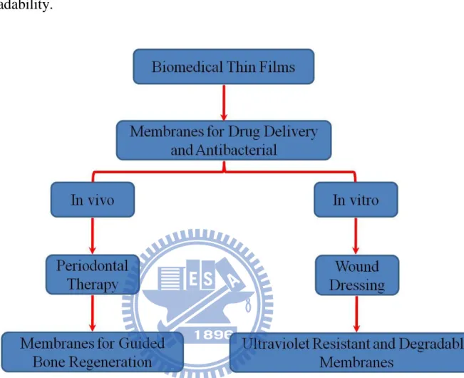
1.4 Objectives of research ... 6
Chapter 2 Electrospinning ... 13
2.1 Introduction ... 13
2.2 Taylor cone ... 15
2.3 Major processing parameters ... 16
2.3.1 Voltage ... 17
2.3.2 Feed rate ... 17
2.3.3 Effect of Collector ... 18
2.3.4 Diameter of Pipette Orifice / Needle ... 18
2.3.5 Distance between Tip and Collector ... 18
2.4 Important features of electrospinning ... 20
2.5 Biodegradable polymer ... 21
2.6 Optimum conditions for electrospinning PLLA fibers ... 22
Chapter 3 Membranes for Drug Delivery and Antibacterial ... 25
3.1 Introduction ... 25
3.2 Experimental procedure ... 29
3.2.1 Materials and Methods ... 29
3.2.2 Fabrication of bacteriostatic Fibers ... 29
3.2.3 Physical and chemical properties ... 30
3.2.4 Antibacterial Test ... 31
3.3 Results and Discussion ... 32
Chapter 4 Membranes for Guided Bone Regeneration ... 43
4.1 Introduction ... 43
ix
4.2.1 Materials and Methods ... 49
4.2.2 Fabrication of Calcium Carbonate Particles ... 49
4.2.3 Fabrication of Guided Bone Regeneration membranes ... 50
4.2.4 Physical and chemical properties ... 50
4.2.5 Analysis of mechanical properties ... 51
4.3 Results and Discussion ... 52
Chapter 5 Ultraviolet Resistant and Degradable Membranes ... 61
5.1 Introduction ... 61
5.2 Experimental procedure ... 66
5.2.1 Materials and Methods ... 66
5.2.2 Fabrication of Composite ultraviolet resistant and high degree of degradable membranes ... 68
5.2.3 Physical and chemical properties ... 69
5.2.4 Ultraviolet Protection Factor (UPF) ... 69
5.2.5 UVA Effectiveness - The Boot's Star System ... 70
5.2.6 UVA Effectiveness - Critical Wavelength ... 71
5.3 Results and Discussion ... 72
Chapter 6 Conclusions ... 82
Chapter 7 Future work ... 87
x
Table of contents
Table 4- 1: Mechanical properties of the electrospun PLLA, PLLA/calcite
and PLLA/aragonite fiber. ... 60
Table 5- 1 Ultraviolet wave-lengths of maximum sensitivity for typical commercial polymers[62] ... 62
Table 5- 2 UPF classification system of sun protective clothing[96] ... 70
Table 5- 3 UVA Effectiveness[96] ... 71
Table 5- 4 Level of Protection (Critical Wavelength)[96] ... 72
xi
Figure of contents
Figure 1- 1 Composite Reinforcement ... 2
Figure 1- 2 General molecular structure of poly(α-hydroxyl acid) family[9, 13] ... 4
Figure 1- 3 Polylactide synthesis[9, 13] ... 4
Figure 1- 4 scope of experiments ... 12
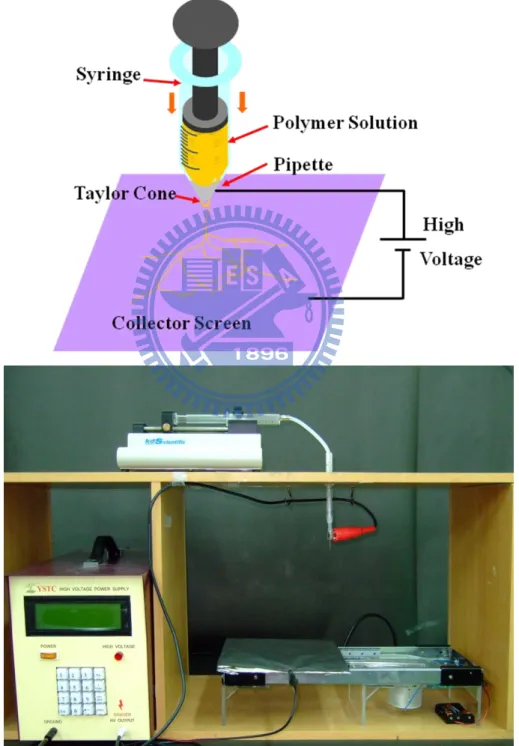
Figure 2- 1 Electrospinning Device Setup ... 14
Figure 2- 2 (a) high voltage power supply (b) KDS100 syringe pump (c) 22 needle gauge ... 15
Figure 2- 3 Taylor cone[17-18] ... 16
Figure 2- 4 SEM images showing the variation of beaded fibers at different feeding rates: (a) 20 ml/min; (b) 75 ml/min[21]... 17
Figure 2- 5 Nylon 6,6 at (a) 2 cm deposition distance and (b) 0.5cm deposition distance[21]. ... 20
Figure 2- 6 High-speed camera observed the fiber spraying process of electrospun ... 23
Figure 2- 7 The optimum conditions for Electrospinning PLLA fibers ... 24
Figure 3- 1 The structure of Chlorhexidine[36, 74] ... 26
Figure 3- 2 Field Emission Scanning electron micrographs of the electrospinning fibers: (a) PLLA fibers, (b) PLLA/CHX fibers image (50:50). ... 32
Figure 3- 3 Fourier Transform Infrared Spectra of PLLA fibers and PLLA/CHX fibers (50:50). ... 33
Figure 3- 4 Micro-Raman spectra of PLLA fibers and PLLA/CHX fibers... 34 Figure 3- 5 (a) (b) (c) are illustrations of interaction between drug released
xii
by drug delivery membranes and growth rates of XL1-Blue in the (a) zero to third hours (b) fourth to ninth hours (c) tenth to twelfth hours (yellow membrane:PLLA/CHX(50:50 volume ratio), Green bacterial: Xl1-Blue) (d) Growth curves of XL1-Blue in LB medium inoculated with 107 CFU of bacteria. The presence of different concentrations of (▲) PLLA/CHX fibers (90:10) and (●) PLLA/CHX fibers (50:50). Another two curves: one is only (▼) poly(L-lactic acid)s fibers; the
other is (■) ampicillin-added 100 µg/mL. ... 37
Figure 3- 6 (a) (b) (c) are illustrations of interaction between drug released by PLLA/CHX(50:50) membranes and growth rates of TOPO XL1-Blue in the (a) zero to fourth hours(b) fifth to tenth hours(c) eleventh to twelfth hours (yellow membrane:PLLA/CHX(50:50 volume ratio), Green bacterial: TOPO Xl1-Blue).(d) Growth curves of TOPO XL1-Blue in LB medium inoculated with 107 CFU of bacteria. The presence of different concentrations of (▲) PLLA/CHX fibers (90:10) and (●) PLLA/CHX fibers (50:50). Another two curves: one is only (▼) poly(L-lactic acid)s fibers; the other is (■) ampicillin-added 100 µg/mL. ... 41
Figure 4- 1 Guided bone regeneration (GBR) membranes[40-42] ... 45
Figure 4- 2 Calcium carbonate phase diagram[56] ... 47
Figure 4- 3 Calcium carbonate Interaction diagram[42, 48] ... 48
Figure 4- 4 lattice structure of (a)calcite and (b)aragonite[57] ... 48
xiii
Figure 4- 6 FTIR spectra of calcite and aragonite showing their
characteristic carbonate vibrational bands. ... 53 Figure 4- 7 Powder X-ray diffractograms of calcite and aragonite. ... 54 Figure 4- 8 Field Emission Scanning electron micrographs of the
electrospinning fibers: (a) PLLA fibers, (b) PLLA/calcite fibers(c)
PLLA/aragonite fibers image. ... 54 Figure 4- 9 Micro-Raman spectra of the synthetically prepared PLLA fibers,
PLLA/calcite fibers and PLLA/aragonite fibers. ... 56 Figure 4- 10 Tensile tests (a) specimen size 25 mm× 70mm× 0.1mm (b)
Instrument setup ... 57 Figure 4- 11 Stress-strain curves of electrospun of PLLA, PLLA/calcite and
PLLA/aragonite fiber. ... 57 Figure 5- 1 The Ultraviolet resistance structure of (a)
2-Hydroxy-4-Octyloxy Benzophenone, (b)
2-(2‘-hydroxy-5‘-methylphenyl) benzotriazole, (c) Tetrakis
[Methylene(3‗,5‘-Di-tert-Butyl-4-hydroxyphenyl) Propionate] methane, and (d) Tris(2,4-di-tert-butylphenyl) phosphate ... 67 Figure 5- 2: SEM Image (a) PLLA , (b) PLLA/Benzophenone-12 , (c)
PLLA/Chemfos-168(d) PLLA/Chemsorb-p ... 73 Figure 5- 3 Micro-Raman spectra of PLLA fibers, PLLA/Benzophenone-12
fibers, PLLA/Chemfos-168 fibers and PLLA/ Chemsorb-p fibers. ... 78 Figure 5- 4 The transmission spectra of (A) PLA , (B)
1
Chapter 1 General Introduction
1.1 The background of the research
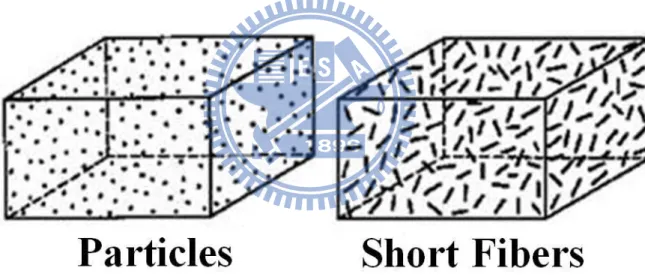
Composites are combination of two distinct material phases, a bulk phase, also known as a matrix and a reinforcement phase. It is the combination of the strength of the reinforcement and the toughness of the matrix that gives composite its superior properties that are not available in any single conventional material[1-2]. Both matrix and reinforcement phases can be metal, ceramic or polymer. Generally, the matrix binds the reinforcement together to give the composite its shape, surface appearance and resistance to environmental damage. While the matrix is usually ductile or tough, the reinforcements are strong with low densities. It is the reinforcement that carries most of the load thus giving the composite its stiffness and strength[3]. When fiber reinforcements of less than l00nm are used, it is possible to produce transparent composites[4] although they are generally opaque due to light scattering. In most cases, composites are designed for loadbearing applications although there are other classes of composites that are used for their interesting electrical, thermal or magnetic properties[5-8].
There are generally two types of composite reinforcements, fibrous reinforcement and particulate reinforcement. In fibrous reinforcement, the fibers arrangement can be of many different forms. The simplest arrangement of the fibers in the matrix is to have the fibers aligned in a certain direction to form a laminate composite. Thin sheets of unidirectional composites can be stacked in an arrangement such that the fibers are oriented at 0°, 90° and +45°
2
directions. Such composite laminates are strong in all directions within the plane containing the fibers but are weak in the direction normal to the plane of the laminates[1-2]. Other types of fiber arrangements include weaving to produce fabrics of different shapes and weave configurations, knitting as well as braiding as seen in Figure 1-1. Depending on the application of the composite, different fiber arrangements are used as reinforcement in the composite. For example, braided fiber can be used as reinforcement for composite where high torsional stiffness is desired. Randomly distributed fibers in the form of non-woven mat can also be used as reinforcement in composite[3].
Figure 1- 1 Composite Reinforcement
1.2 Biodegradable materials
Polylactic acid or polylactide (PLA) is a biodegradable, thermoplastic, aliphatic polyester derived from renewable resources, such as corn starch or sugarcanes[9]. PLA is a sustainable alternative to petrochemical-derived products, since the lactides from which it is ultimately produced can be
3
derived from the fermentation of agricultural by-products such as corn starch or other carbohydrate-rich substances like maize, sugar or wheat. PLA has a crystallinity of around 37%, a glass transition temperature between 50-80 °C and a melting temperature between 173-178 °C[10]. PLA has similar mechanical properties to PETE polymer, but has a significantly lower maximum continuous use temperature[11-12]. Due to the chiral nature of lactic acid, several distinct forms of polylactide exist: Poly(α-L-alanine) (PLLA) is the product resulting from polymerization of L, L-lactide (also known as L-lactide).The melting temperature of PLLA can be increased 40-50 °C and its heat deflection temperature can be increased from approximately 60°C to up to 190 °C by physically blending the polymer with PDLA (poly-D-lactide). Polymerization of a racemic mixture of L- and D-lactides[13] usually leads to the synthesis of poly-DL-lactide (PDLLA) which is amorphous. The degree of crystallinity, and hence many important properties, is controlled by the ratio of D to L enantiomers used.
PLA belongs to the poly(α-hydroxyl acid) family (Figure 1-2) with a methyl group attached to the R position, which makes it the second simplest poly(α-hydroxyl acid) after polyglycolide which has only one hydrogen atom in the R position.PLA can be obtained by polycondensation or by step-growth polymerization of lactic acid. High molecular weight PLA is, however, normally formed by a ring-opening polymerization of lactide, or the dimer of lactic acid, as is shown in figure 1-3.
4
Figure 1- 2 General molecular structure of poly(α-hydroxyl acid) family[9, 13]
Figure 1- 3 Polylactide synthesis[9, 13]
PLA is currently used in a number of biomedical applications, such as sutures, stents, dialysis media and drug delivery devices. It is also being evaluated as a material for tissue engineering. Because it is biodegradable, it can also be employed in the preparation of bioplastic, useful for producing loose-fill packaging, compost bags, food packaging, and disposable tableware. In the form of fibers and non-woven textiles, PLA also has many potential uses, for example as upholstery, disposable garments, awnings, feminine hygiene products, and nappies[9, 13].
5
In the late 1500s William Gilbert set out to describe the behaviour of magnetic and electrostatic phenomena. He observed that when a suitably electrically charged piece of amber was brought near a droplet of water it would form a cone shape and small droplets would be ejected from the tip of the cone: this is the first recorded observation of electrospraying. The process of electrospinning was patented by J.F Cooley in February 1902[14] and by W.J. Morton in July 1902[15]. In 1914 John Zeleny, published work on the behaviour of fluid droplets at the end of metal capillaries. His effort began the attempt to mathematically model the behaviour of fluids under electrostatic forces[16].
Between 1964 and 1969 Sir Geoffrey Ingram Taylor produced the theoretical underpinning of electrospinning[17-18]. Taylor‘s work contributed to electrospinning by mathematically modelling the shape of the cone formed by the fluid droplet under the effect of an electric field; this characteristic droplet shape is now known as the Taylor cone. He further worked with J. R. Melcher to develop the ―leaky dielectric model‖ for conducting fluids[18]. In the early 1990s several research groups (notably that of Reneker and Rutledge who popularised the name electrospinning for the process)[19] demonstrated that many organic polymers could be electrospun into nanofibers. Since then, the number of publications about electrospinning has been increasing exponentially every year[20].
The electrospinning process, in its simplest form consisted of a pipette to hold the polymer solution, two electrodes and a DC voltage supply in the kV range. The polymer drop from the tip of the pipette was drawn into a fiber due to the high voltage. The jet was electrically charged and the charge caused the
6
fibers to bend in such a way that every time the polymer fiber looped, its diameter was reduced. The fiber was collected as a web of fibers on the surface of a grounded target[21].
Electrospinning is a simple and versatile method for fibers preparation, which employs electrostatic forces that strength a polymer jet to generate continuous fibers with diameters ranging from micrometers down to several nanometers[22-23]. Electrospinning is an interesting technique for spinning PLLA[24]. The process offers an excellent opportunity for designing the surface morphology and porosity of the fibers to provide the most appropriate interface for biomedical application[10, 12, 25-27].
1.4 Objectives of research
Figure 1-4 Experiment construction flow chart. Research on Controlled release of drugs is a very important process to achieve the highest therapeutic efficiency. Much research has been carried out in order to develop of new and/or improved drug therapies that are more efficient and, most importantly, more cost-effective. The conventional definition of controlled release is a constant level of drugs in suitable systems. Electrospun fibers was a novel process to prepare and the release characteristics should depend on interaction between polymer and drug pair as much as on the sizes of fibers[28]. Polymeric drug delivery systems plays an important role in conventional dosage forms, such as improved therapeutic effect, reduced toxicity, convenience, and so on. In previous study, the drugs can be capsulated directly into electrospun fibers and these systems show nearly zero-order kinetics of drug release[29].
7
Previous studies fabricated effective bacteria inhibiting fiber membranes from Polymer/Silver nanoparticles[30-31] & Polymer/chitosan[32-34] via electrospinning. In addition, when it comes to bacteria inhibiting drug, such as CHX[35], CHX-CA[36], CHX-Digluconate[37], and CHX-gluconate, only the delivery efficiency of Polymer/CHX, or just that of CHX, has been discussed[36-37]. Tests on the inhibiting capability (Inhibition Zone) of Polymer/CHX matrix were rarely done. Evaluations of bacteria inhibiting capability based on Inhibition Zone were only qualitative, not quantitative. This study aimed to discuss whether biodegradable inhibiting drug delivery membranes fabricated from PLLA/CHX via electrospinning possessed the characteristics of drug delivery systems and whether CHX could still inhibit bacteria after being released from PLLA. This experiment quantitatively evaluated bacteria growth in liquid culture by observing Optical Density 600nm (OD) at one-hour intervals, and used the growth curves thus derived to evaluate on a real-time the impacts of drug delivery speeds on the growth rates of bacteria in different phases. Competent cell and plasmid inserted competent cell, bacteria that are of the same strain but grow at different speeds were utilized to interact with biodegradable CHX delivery membranes fabricated via electrospinning to determine whether such drug delivery membranes are a rate-preprogrammed drug delivery system.
A major goal of periodontal regeneration therapy is the regeneration of lost supporting tissue, including the alveolar bone, periodontal ligament, and cementum around a previously diseased tooth root[38-39]. Guided tissue regeneration (GTR) has accomplished this goal, and has become a standard
8
procedure for periodontal regeneration therapy since it was initially suggested for such therapy[40-42]. In addition, it has been applied to bone and peri-implant defects, and for bone augmentation procedures prior to implant placement. In such situations, it is sometimes termed guided bone regeneration (GBR)[42-44]. For the membrane to be effective, it must satisfy criteria such as excellent biocompatibility, controllable biodegradability, cytocompatibility, suitable microstructure (pore size and porosity) and mechanical properties[45-47].
In previous studies, although present polymeric products show positive results in clinical studies, their weak mechanical properties and poor bone regeneration capacity are still major challenges[42]. To overcome these problems, recent research efforts have included the incorporation of bone-like ceramics into the membranes, e.g. hydroxyapatite, tricalcium phosphate and calcium carbonate[42, 44, 48-49]. Hydroxyapatite (HA,Ca10[PO4]6[OH]2) is the
main mineral component of natural bone and has good biocompatibility, osteoconductivity and bioactivity, and thus it is suitable for making the guided bone regeneration membranes[50]. However, the brittleness of hydroxyapatite limits its applicability[51]. The co-precipitation of HA nanocrystals in soluble collagen has met with partial success in the fabrication of HA–collagen nanocomposites similar to the nanostructure of real bone[52], though with weaker mechanical properties. Calcium carbonate has been recognized as bone filling material and its good osteoconductivity has been approved in recent studies[44, 53-55].
Polymorphism in materials science is the ability of a solid material to exist in more than one form or crystal structure. Polymorphism can potentially be
9
found in any crystalline material. Calcium carbonate is one of the most common biological minerals and has polymorphs of calcite, aragonite, and to a less extent amorphous state, vaterite or monohydrate in calcareous structures of organisms[56]. Calcium carbonate can be precipitated in aqueous solution as three anhydrous polymorphs, calcite, aragonite and vaterite, and three hydrated forms, amorphous calcium carbonate, calcium carbonate hexahydrate and calcium carbonate monohydrate[57-58].
The calcite has a trigonal and the aragonite has an orthorhombic crystal structure. The latter has typically higher elasticity modulus than the powder, better dispersibility due to the surface treatment, increased impact strength, tensile strength and elongation at break[59]. So far, most GTR/GBR membranes are made in the shape of porous foam, created by traditional methods such as particulate leaching, solvent casting or gas foaming[60]. Electrospinning is a simple and versatile method for fibers preparation, which employs electrostatic forces that strength a polymer jet to generate continuous fibers with diameters ranging from micrometers down to several nanometers[22]. Fibers obtained from electrospinning are in the range of 50 nm to a few microns in diameter and generally collected in the form of a non-woven structure[23]. It has already been shown that electrospun membranes have the potential to promote osteoblastic cell function and bone regeneration[42].
When plastics are used for outdoor applications, they often deteriorate fairly rapidly. Theoretical explanation is based upon absorption of ultraviolet energy, raising some bonds to an energy level which exceeds their stability, and thus initiating their breakdown, usually involving atmospheric oxidation and
10
sometimes hydrolysis as well. Many of the newer engineering plastics offer high performance in their mechanical, thermal, and chemical properties, but still cannot be recommended for use out-of-doors[61].
Ultraviolet radiation can be classified into UV-A, UV-B, and UV-C regions. Much less is known about the biological effects of UV-A radiation (320–400 nm), which adjoins the visible light, so the waveband is usually not a topic of discussion. Most observed biological effects of UV-B (280–320 nm) radiation are extremely detrimental to living organisms[62]. Because solar UVR below wavelengths of 290 nm is effectively absorbed by stratospheric ozone, and no such radiation reaches living organisms from natural sources, the wavelength in the UV-C region (200–280 nm) is considered of little detriment to human beings. Ultraviolet radiation (UV-A、UV-B、UV-C can cause damage to C-H, C-C, O-H, C-Cl, etc. in living organisms, and substance with the same bond energy. In order to solve the polymer composite material is not suitable for outdoor issues, often in the processing additives are added to solve this problem a little[61-63]. Many common additives, such as : UV Absorber : Benzophenone、Phosphite Antioxidant、Hindered Amine Light Stabilizers (HALS):Hindered Amine Light Stabilizer[64]。
Polylactide (PLA) is one of the most promising biodegradable polymers owing to its mechanical property profile, thermoplastic processibility and biological properties, such as biocompatibility and biodegradability. The use of synthetic degradable polyesters in surgery as suture materials and bone fixation devices has three decades of history. Degradable polyesters derived from three monomers, lactide, glycolide and caprolactone, are commonly used clinically.
11
They are characterized by degradation times ranging from days to years, depending on formulation and initial molecular weight[10].
The majority of the studies on electrospinning fibers of PLLA to add Benzophenone -12[65-68] and Chemfos-168[69-70] from solutions, we have reported that molecular structures and antiultraviolet of electrospinning nanofibers. Benzophenone can be used as a photo initiator in UV-curing applications such as inks, imaging and clear coatings in the printing industry. Benzophenone prevents ultraviolet (UV) light from damaging scents and colours in products such as perfumes and soaps. It can also be added to the plastic packaging as a UV blocker. This allows manufacturers to package the product in clear glass or plastic. Without it, opaque or dark packaging would be used. In laboratories, solvents are often distilled with sodium and benzophenone as desicants. The product of these two chemicals in the absence of air and water is a dark blue ketyl; a solution of this ketyl can be used to qualitatively test for the absence of air and water. Chemfos-168 is an antioxidant is a molecule capable of slowing or preventing the oxidation of other molecules. Oxidation is a chemical reaction that transfers electrons from a substance to an oxidizing agent. Oxidation reactions can produce free radicals, which start chain reactions that damage cells. Antioxidants terminate these chain reactions by removing free radical intermediates, and inhibit other oxidation reactions by being oxidized themselves. As a result, antioxidants are often reducing agents such as thiols or polyphenols.
In this study, we investigated ultraviolet resistance of the PLLA, PLLA / UV absorption and PLLA / anti-oxidation agents by electrospinning. It is believed that this study could provide a good insight into ultraviolet resistance
12
properties of the electrospinning polymer. We also hope to make the ultraviolet resistance electrospinning fibers and have high degree of degradability.
13
Chapter 2 Electrospinning
2.1 Introduction
In the late 1500s William Gilbert set out to describe the behaviour of magnetic and electrostatic phenomena. He observed that when a suitably electrically charged piece of amber was brought near a droplet of water it would form a cone shape and small droplets would be ejected from the tip of the cone: this is the first recorded observation of electrospraying. The process of electrospinning was patented by J.F Cooley in February 1902[14] and by W.J. Morton in July 1902[15]. In 1914 John Zeleny, published work on the behaviour of fluid droplets at the end of metal capillaries. His effort began the attempt to mathematically model the behaviour of fluids under electrostatic forces[16].
Between 1964 and 1969 Sir Geoffrey Ingram Taylor produced the theoretical underpinning of electrospinning[17-18]. Taylor‘s work contributed to electrospinning by mathematically modelling the shape of the cone formed by the fluid droplet under the effect of an electric field; this characteristic droplet shape is now known as the Taylor cone. He further worked with J. R. Melcher to develop the ―leaky dielectric model‖ for conducting fluids[18]. In the early 1990s several research groups (notably that of Reneker and Rutledge who popularised the name electrospinning for the process)[19] demonstrated that many organic polymers could be electrospun into nanofibers. Since then, the number of publications about electrospinning has been increasing exponentially every year[20].
The electrospinning process, in its simplest form consisted of a pipette to hold the polymer solution, two electrodes and a DC voltage supply in the kV
14
range. The polymer drop from the tip of the pipette was drawn into a fiber due to the high voltage. The jet was electrically charged and the charge caused the fibers to bend in such a way that every time the polymer fiber looped, its diameter was reduced. The fiber was collected as a web of fibers on the surface of a grounded target[21] (Figure 2-1).
15
Figure 2- 2 (a) high voltage power supply (b) KDS100 syringe pump (c) 22 needle gauge
2.2 Taylor cone
In electrospinning, a high voltage is applied to a polymer fluid such that charges are induced within the fluid. When charges within the fluid reached a critical amount, a fluid jet will erupt from the droplet at the tip of the needle resulting in the formation of a Taylor cone[17-18]. The electrospinning jet will travel towards the region of lower potential, which in most cases, is a grounded collector. There are many parameters that will influence the morphology of the resultant electrospun fibers. The parameters affecting electrospinning and the fibers may be broadly classified into polymer solution
16
parameters, processing conditions which include the applied voltage, temperature and effect of collector, and ambient conditions. With the understanding of these parameters, it is possible to come out with setups to yield fibrous structures of various forms and arrangements. It is also possible to create nanofiber with different morphology by varying the parameters.
Figure 2- 3 Taylor cone[17-18]
2.3 Major processing parameters
Another important parameter that affects the electrospinning process is the various external factors exerting on the electrospinning jet. This includes the voltage supplied, the feedrate, temperature of the solution, type of collector, diameter of needle and distance between the needle tip and collector. These parameters have a certain influence in the fiber morphology.
17 2.3.1 Voltage
A crucial element in electrospinning is the application of a high voltage to the solution.. The high voltage will induce the necessary charges on the solution and together with the external electric field, will initiate the electrospinning process when the electrostatic force in the solution overcomes the surface tension of the solution. Generally, both high negative or positive voltage of more than 10kV is able to cause the solution drop at the tip of the needle to distort into the shape of a Taylor Cone during jet initiation[17].
2.3.2 Feed rate
The feedrate will determine the amount of solution available for electrospinning. For a given voltage, there is a corresponding feedrate if a stable Taylor cone is to be maintained. When the feedrate is increased, there is a corresponding increase in the fiber diameter or beads size as shown in Figure 2-3[21].
Figure 2- 4 SEM images showing the variation of beaded fibers at different feeding rates: (a) 20 ml/min; (b) 75 ml/min[21].
However, there is a limit to the increase in the diameter of the fiber due to higher feedrate. If the feed rate is at the same rate which the solution is carried
18
away by the electrospinning jet, there must be a corresponding increased in charges when the feed rate is increased. Thus there is a corresponding increased in the stretching of the solution which counters the increased diameter due to increased volume.Due to the greater volume of solution drawn from the needle tip, the jet will takes a longer time to dry. As a result, the solvents in the deposited fibers may not have enough time to evaporate given the same flight time. The residual solvents may cause the fibers to fuse together where they make contact forming webs. A lower feedrate is more desirable as the solvent will have more time for evaporation.
2.3.3 Effect of Collector
There must be an electric field existed between the source and the collector for electrospinning to initiate. Thus in most electrospinning setup, the collector plate is made out of conductive material such as aluminum foil which is electrically grounded so that there is a stable voltage potential difference between the source and the collector.
2.3.4 Diameter of Pipette Orifice / Needle
The internal diameter of the needle or the pipette orifice has a certain effect on the electrospinning process. A smaller internal diameter was found to reduce the clogging as well as the amount of beads on the electrospun fibers.
2.3.5 Distance between Tip and Collector
19
affect the electrospinning process and the resultant fibers. Varying the distance between the tip and the collector will have a direct influence in both the flight time and the electric field strength. For independent fibers to form, the electrospinning jet must be allowed time for most of the solvents to be evaporated. When the distance between the tip and the collector is reduced, the jet will have a shorter distance to travel before it reaches the collector plate. Moreover, the electric field strength will also increase at the same time and this will increase the acceleration of the jet to the collector. As a result, there may not have enough time for the solvents to evaporate when it hits the collector. When the distance is too low, excess solvent may cause the fibers to merge where they contact to form junctions resulting in inter and intra layer bonding as shown in Figure 2-4[21].
This interconnected fiber mesh may provide additional strength to the resultant scaffold.Depending on the solution property, the effect of varying the distance may or may not have a significant effect on the fiber morphology. In some cases, changing the distance has no significant effect on the fiber diameter. However, beads were observed to form when distance was too low. The formation of beads may be the result of increased field strength between the needle tip and the collector. Decreasing the distance has the same effect as increasing the voltage supplied and this will cause an increased in the field strength. As mentioned earlier, if the field strength is too high, the increased instability of the jet may encourage beads formation.
However, if the distance is such that the field strength is at an optimal value, there is less beads formed as the electrostatic field provides sufficient stretching force to the jet.
20
Figure 2- 5 Nylon 6,6 at (a) 2 cm deposition distance and (b) 0.5cm deposition distance[21].
2.4 Important features of electrospinning
1.Suitable solvent should be available for dissolving the polymer.
2.The vapor pressure of the solvent should be suitable so that it evaporates quickly enough for the fiber to maintain its integrity when it reaches the target but not too quickly to allow the fiber to harden before it reaches the nanometer range.
3.The viscosity and surface tension of the solvent must neither be too large to prevent the jet from forming nor be too small to allow the polymer solution to drain freely from the pipette.
4.The power supply should be adequate to overcome the viscosity and surface tension of the polymer solution to form and sustain the jet from the pipette. 5.The gap between the pipette and grounded surface should not be too small to
create sparks between the electrodes but should be large enough for the solvent to evaporate in time for the fibers to form.
21
2.5 Biodegradable polymer
Poly(lactic acid) or polylactide (PLA) is a thermoplastic aliphatic polyester derived from renewable resources, such as corn starch (in the United States), tapioca products (roots, chips or starch mostly in Asia) or sugarcanes (in the rest of world). It can biodegrade under certain conditions, such as the presence of oxygen, and is difficult to recycle.
Due to the chiral nature of lactic acid, several distinct forms of polylactide exist: poly-L-lactide (PLLA) is the product resulting from polymerization of L,L-lactide (also known as L-lactide). PLLA has a crystallinity of around 37%, a glass transition temperature between 60-65 °C, a melting temperature between 173-178 °C and a tensile modulus between 2.7-16 GPa. PLA has similar mechanical properties to PETE polymer, but has a significantly lower maximum continuous use temperature. Polylactic acid can be processed like most thermoplastics into fiber (for example using conventional melt spinning processes) and film. The melting temperature of PLLA can be increased 40-50 °C and its heat deflection temperature can be increased from approximately 60°C to up to 190 °C by physically blending the polymer with PDLA (poly-D-lactide). PDLA and PLLA form a highly regular stereocomplex with increased crystallinity. The temperature stability is maximised when a 50:50 blend is used, but even at lower concentrations of 3-10% of PDLA, there is still a substantial improvement. In the latter case, PDLA acts as a nucleating agent, thereby increasing the crystallization rate. Biodegradation of PDLA is slower than for PLA due to the higher crystallinity of PDLA. PDLA has the useful property of being optically transparent.
22
2.6
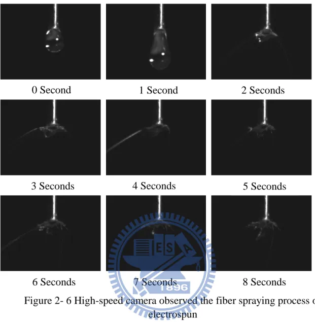
Optimum conditions for electrospinning PLLA fibersThe polymer fibers were injected in by using a 10mL glass syringe with a 22 needle gauge (0.7mm OD×0.4mm ID) at a flow rate of 0.2mL/hour, which was controlled by using a KDS100 pump from YEONG-SHIN CO., LTD. Hsinchu, Taiwan. The high voltage power supply used was a 30KV∕15W model purchased from YOU-SHANG TECHNICAL CORP. Kaohsiung, Taiwan. The equipment was attached to the needle tip through an alligator clip and voltage was 20KV; the tinfoil grounded target was placed at 15cm away from the needle tip. It could be observed by the High-speed camera that in Figure 2-6.
Poly(α-L-alanine) (CAS No:77160-91-9, C3H7NO2, PLLA) is a
biodegradable, thermoplastic, aliphatic polyester derived from renewable resources, such as corn starch or sugarcanes. PLLA, purchased from Sigma, Taiwan, has a molecular weight of 180~200 KDa with a volume concentration of 12%, i.e. 12g PLLA dissolved in 100ml ACS grade>99.8% chloroform.
23
Figure 2- 6 High-speed camera observed the fiber spraying process of electrospun
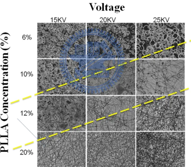
The polymer fibers were injected in by using a 10mL glass syringe with a 22 needle gauge (0.7mm OD×0.4mm ID) at a flow rate of 0.2mL/hour, which was controlled by using a KDS100 pump from YEONG-SHIN CO., LTD. Hsinchu, Taiwan. The high voltage power supply used was a 30KV∕15W model purchased from YOU-SHANG TECHNICAL CORP. Kaohsiung, Taiwan. The equipment was attached to the needle tip through an alligator clip and voltage difference in 15KV, 20KV and 25KV was used; the tinfoil grounded target was placed at 15cm away from the needle tip. Poly(α-L-alanine) (CAS No:77160-91-9, C3H7NO2, PLLA) is a biodegradable, thermoplastic, aliphatic
0 Second 1 Second 2 Seconds
3 Seconds 4 Seconds 5 Seconds
6 Seconds s
24
polyester derived from renewable resources, such as corn starch or sugarcanes. PLLA, purchased from Sigma, Taiwan, has a molecular weight of 180~200 KDa with a volume concentration of 6%, 10%, 12%, and 20%. It could be observed by the optical microscope that in Figure 2-7. We recognize the optimum conditions for electrospinning PLLA fibers at 20KV 12%PLLA 15cm 25℃ 0.2mL/hour 22 needle gauge (0.7mm OD×0.4mm ID).
25
Chapter 3 Membranes for Drug Delivery and Antibacterial
3.1 Introduction
Development of new drug molecule is expensive and time consuming. Improving safety efficacy ratio of ―old‖ drugs has been attempted using different methods such as individualizing drug therapy, dose titration and therapeutic drug monitoring. Delivering drug at controlled rate, slow delivery, targeted delivery are other very attractive methods and have been pursued very vigorously. Drug delivery is playing a significant role in the pharmaceutical industry such that new drug delivery systems and a diverse range of technology options have emerged. A recent industry survey estimated that there are more than 300 companies engaged in the development and licensing of drug delivery technology. The drug delivery market is currently estimated to be worth approximately $50 billion, and worldwide sales could reach as much as $100 billion by 2005[71].
Currently available polymers for controlled release can be classified into four major categories: (1) diffusion-controlled systems, (2) solvent-activated systems, (3) chemically controlled systems, and (4) magnetically controlled systems[72-73].
Chlorhexidine (CHX) (Figure 3-1) has been widely used as an effective antibacterial agent in applications that range from common disinfectants to bactericidal agents in dentistry; this is largely due to its broad range of antimicrobial activities against bacteria and fungi, high killing rate and nontoxicity toward mammalian cells[36, 74].
26
symmetrically positioned chlorophenyl guanide groups can penetrate through the cellular wall of bacteria and irreversibly disrupt the bacterial membrane, thus killing the microorganism. In most materials that include CHX as the biocide, CHX is simply enmeshed within the material and gradually leaches out to kill the bacteria[36].
In the past 30 years, chlorhexidine, a bacterial membrane permeabilizing agent and its water-soluble derivative chlorhexidine digluconate has been used extensively in mouth rinses to control bacteria biofilms on teeth[37, 75].
Figure 3- 1 The structure of Chlorhexidine[36, 74]
Research on Controlled release of drugs is a very important process to achieve the highest therapeutic efficiency. Much research has been carried out in order to develop of new and/or improved drug therapies that are more efficient and, most importantly, more cost-effective. The conventional definition of controlled release is a constant level of drugs in suitable systems. Electrospun fibers was a novel process to prepare and the release characteristics should depend on interaction between polymer and drug pair as much as on the sizes of fibers[28].
27
dosage forms, such as improved therapeutic effect, reduced toxicity, convenience, and so on. In previous study, the drugs can be capsulated directly into electrospun fibers and these systems show nearly zero-order kinetics of drug release[29].
Electrospinning is a simple and versatile method for fibers preparation, which employs electrostatic forces that strength a polymer jet to generate continuous fibers with diameters ranging from micrometers down to several nanometers[23, 25].
Poly(α-L-alanine) (PLLA) is one of the most promising biodegradable polymers owing to its mechanical property profile, thermoplastic processibility and biological properties, such as biocompatibility and biodegradability. Electrospinning is an interesting technique for spinning PLLA. The process offers an excellent opportunity for designing the surface morphology and porosity of the fibers to provide the most appropriate interface for biomedical application[12, 25-27].
Chlorhexidine (CHX) is a bactericidal agent. Its effect on E. coli and S. aureus is dependent on CHX concentration and pH. It‘s found that, by using C14 chlorhexidine gluconate, the uptake by bacteria becomes extremely rapid, with a maximum effect occurring within 20 seconds[75]. Damage to outer cell layers takes place but is insufficient to induce lysis or cell death. The agent then crosses cell walls or outer membranes, presumably by passive diffusion, and subsequently attacks bacterial cytoplasmic or inner membranes. In previous studies, interaction of chlorhexidine with carboxyl, sulfate, and phosphate groups was studied in vitro, including factors that might interfere with these interactions. The properties of cetylpyridine in the same systems also were
28
investigated for comparison, as this is a basic antibacterial agent with virtually no plaque inhibiting effect[36-37, 74-75].
Previous studies fabricated effective bacteria inhibiting fiber membranes from Polymer/Silver nanoparticles[30-31] & Polymer/chitosan[32-34] via electrospinning. In addition, when it comes to bacteria inhibiting drug, such as CHX[35], CHX-CA[36], CHX-Digluconate[37], and CHX-gluconate, only the delivery efficiency of Polymer/CHX, or just that of CHX, has been discussed[36-37]. Tests on the inhibiting capability (Inhibition Zone) of Polymer/CHX matrix were rarely done. Evaluations of bacteria inhibiting capability based on Inhibition Zone were only qualitative, not quantitative. This study aimed to discuss whether biodegradable inhibiting drug delivery membranes fabricated from PLLA/CHX via electrospinning possessed the characteristics of drug delivery systems and whether CHX could still inhibit bacteria after being released from PLLA. This experiment quantitatively evaluated bacteria growth in liquid culture by observing Optical Density 600nm (OD) at one-hour intervals, and used the growth curves thus derived to evaluate on a real-time the impacts of drug delivery speeds on the growth rates of bacteria in different phases. Competent cell and plasmid inserted competent cell, bacteria that are of the same strain but grow at different speeds were utilized to interact with biodegradable CHX delivery membranes fabricated via electrospinning to determine whether such drug delivery membranes are a rate-preprogrammed drug delivery system.
29
3.2 Experimental procedure
3.2.1 Materials and Methods
Poly(α-L-alanine) (CAS No:77160-91-9, C3H7NO2, PLLA) is a
biodegradable, thermoplastic, aliphatic polyester derived from renewable resources, such as corn starch or sugarcanes. PLLA, purchased from Sigma, Taiwan, has a molecular weight of 180~200 KDa with a volume concentration of 12%, i.e. 12g PLLA dissolved in 100ml ACS grade>99.8% chloroform. chlorhexidine gluconate, acquired from J.T. Backer, has a volume concentration of 0.5%, i.e. 5mg chlorhexidine gluconate dissolved in 1000ml 70% Isopropyl Alcohol.
3.2.2 Fabrication of bacteriostatic Fibers
The polymer fibers were injected in by using a 10mL glass syringe with a 22 needle gauge (0.7mm OD×0.4mm ID) at a flow rate of 0.2mL/hour, which was controlled by using a KDS100 pump from YEONG-SHIN CO., LTD. Hsinchu, Taiwan. The high voltage power supply used was a 30KV∕15W model purchased from YOU-SHANG TECHNICAL CORP. Kaohsiung, Taiwan. The equipment was attached to the needle tip through an alligator clip and voltage difference of 20KV was used; the tinfoil grounded target was placed at 15cm away from the needle tip.
First, PLLA, PLLA/CHX (90:10 in terms of volume), and PLLA/CHX (50:50 in terms of volume) solution were injected into 10mL syringes. Next, a syringe pump was used to control the 10mL syringes with PLLA/CHX solution to flow at 0.2mL/hour. The syringe needle was stainless steel, while the
30
collector was tinfoil paper. The distance between the syringe tip and the collector was 15cm. Then, the high power supply was connected to the syringe tip and the collector; the positive electrode was on the syringe tip side, and the negative electrode was on the collector side. The high power supply was turned on to 20KV to observe the spinning fibers on the collector. The structural and optical properties were investigated by a Scanning Electron Microscope (SEM), micro-Raman system and tensile tests. All the experiments were performed at room temperature, about 25℃.
3.2.3 Physical and chemical properties
The fibers were examined by a Field Emission Scanning Electron Microscope (FE-SEM) to visualize their morphology by using a JSM-6700F (JEOL Ltd.). The fiber samples were coated with a thin layer of palladium in 100sec at 20mA by the auto fine coater JFC-1600 (JEOL Ltd.). The fibers were examined by a Fourier Transform Infrared Spectroscopy (FTIR) to analysis of chemical compound by using a Perkin-Elmer Spectrum One FTIR Spectroscopy ( Analytical & Bio Science Instrument Co., Ltd., Taipei, Taiwan). The Fourier Transform Infrared Spectroscopy was used and set at absorbance mode, 500 (cm-1) to 2000 (cm-1) wavelength with a resolution of 4 cm-1. Raman scattering measurements were performed in the TRIAX 550 micro-Raman system. The 5145 Å line with a power of 0.2 W from the Coherent Innova Argon ion laser was focused to about 2 ~ 4 μm on the sample surface. The back-scattered signal was collected by a microscopic system and recorded with a JOBIN-YVON SPEX SPECTRUM ONE liquid nitrogen cooled CCD detector. All spectra were recorded by an OLYMPUS microscope objective and 3 accumulations at 300
31
seconds integration time with ~50 mW power on the sample for each Raman spectrum. Frequencies were to ± 2 cm-1 accurately as determined from plasma emission lines. The frequency of each Raman band reported in this study was obtained using Lorentzian curve fitting.
3.2.4 Antibacterial Test
The competent cells used in this experiment, XL1-Blue Escherichia coli (E. coli) Strain from Stratagene, were purchased from Invitrogene, the same company from which TOPO plasmid was obtained.,TOPO Xl1-Blue were XL1-Blue inserted with TOPO plasmid by means of heat shock. XL1-blue Escherichia coli and TOPO XL1-Blue were cultured in Luria-Bertani (LB) broth (from Difico Co Ltd, Taipei, Taiwan) and LB agar plates were supplemented with 100 µg/mL of ampicillin for cloning and maintenance. The cells were grown at 37°C and 200 rpm to mid-logarithmic phase (Optical Density 600nm of 0.8) Growth rates and bacterial concentrations were determined by measuring optical density (OD) at 600 nm each 30 min (OD of 0.1 corresponds to a concentration of 108 cells per cm3). PLLA, PLLA/CHX(90:10) and PLLA/CHX(50:50) membrane size is 18×18mm, similar to the size of cover slip.
XL1-Blue and TOPO XL1-Blue were used to evaluate the bacteria/plague inhibiting capability of the CHX releasing membranes by observing their bacteria growth curves. First of all, one colony from the LB agar plate of XL1-Blue and one colony from that of TOPO XL1-Blue were collected and respectively placed into culture tubes containing 5mL of Luria-Bertani (LB) broth. The tubes were then put in an incubator at 37℃ at 200rpm for six to eight hours (until Optical Density=0.8). Next, ten 1L Erlenmeyer flasks containing
32
500mL of LB broth medium, sterilized by Autoclave at 120℃ under 1.2 kgf/cm2 for 15 minutes, and cooled down for 3 hours, were prepared. The ten flasks were divided into two groups of five. One group was added with 0.2mL of XL1-Blue (Optical density=0.8), while the other was added with 0.2mL of TOPO XL1-Blue (Optical density=0.8). In each group, only the first flask (control group) was not added with the drug delivery membranes and PLLA fibers, PLLA/CHX fibers (50:50), PLLA/CHX fibers (90:10), and 100 µg/mL of ampicillin solution were respectively added into the other four flasks.
3.3 Results and Discussion
It could be observed by the electronic microscope that, in Figure 3-2(a), the fiber diameter of PLLA was approximately 3~5μm and on the surface of the fibers were pores at the size of around 10nm. In Figure 3-2(b), the fiber diameter of PLLA/CHX was approximately 600~900nm and the surface was smooth. It was further observed that PLLA/CHX fibers tended to overlap and formed a structure of 2~3 fiber tubes.
Figure 3- 2 Field Emission Scanning electron micrographs of the electrospinning fibers: (a) PLLA fibers, (b) PLLA/CHX fibers image (50:50).
33
In this experiment, the original intent was to understand, by means of FTIR & Raman Spectroscopy, if CHX was successfully mixed with PLLA solution to fabricate via electrospinning biodegradable PLLA fiber membranes that contained CHX. FTIR spectra of analyzed polymers were demonstrated in Figure 3-3. The band originating from C=O stretching vibrations was situated at 1745 cm-1 for Poly lactide[76]. In the range 1050-1250 cm-1 C-O and C-O-C stretching vibrations could be attributed. There were three bands in the range 1300-1500 cm-1 in PLLA spectrum that might attribute to symmetric and asymmetric deformational vibrations of C-H in CH3 groups[13].
Figure 3- 3 Fourier Transform Infrared Spectra of PLLA fibers and PLLA/CHX fibers (50:50).
However, in the FTIR experiment, the characteristic IR peaks of CHX were observed between 1500 cm-1 and 1650 cm-1 (C=N stretching and aromatic C=C bending vibrations, respectively)[36] and PLLA demonstrated a
34 very strong peak νC=O at 1760 cm-1
, so we could not confirm via FTIR whether the biodegradable PLLA fiber membranes contained CHX. FTIR could at most confirm that PLLA was used in the experiment. (In the FTIR spectrum of the PLLA film, the most pronounced difference with the spectra of individual homopolymers was the disappearance of the absorption peak at 1270 cm-1.[13, 76])
Therefore, to confirm the existence of CHX in the fiber membranes, Micro-Raman Spectroscope was utilized to conduct fiber membrane analyses at CH3 and CH bending region. The CH3 asymmetric deformation modes
appeared at about 1450±2cm-1 as intense Raman and IR bands in all the compounds[76-77].
Figure 3- 4 Micro-Raman spectra of PLLA fibers and PLLA/CHX fibers.
In the Raman spectra of the PLLA/CHX fibers, the characteristic CHX peak at 1604 cm-1, as indicated by an arrow in Figure 3-4, was observed. The
35
peak shifted 34 cm-1 to higher wavenumbers compared to that of pure CHX powders (1570 cm-1)[35-36], which could be attributed to the interaction between CHX and the polymer matrix in the fibers. As mentioned in previous literature, the I875/I1452 Raman intensity ratio signaled results of bio-degradation and structural differences[76-77]. In this experiment, although both were bio-degradable membranes, the I875/I1452 Raman intensity ratio of PLLA fiber membranes was 1.494 while that of PLLA/CHX fiber membranes was 1.304.
Figure 3-5(a)(b)(c) illustrated the interactions between the PLLA/CHX (50:50) drug releasing membranes and XL1-Blue. Figure 3-5(d) was the bacteria growth curves derived by observing the ODs (Optical Density 600nm) of the 1mL broth extracted from flasks of various conditions at one-hour intervals. As ampicillin, a form of antibiotics, could effectively inhibit the growth of XL1-Blue, no growth was observed (Optical Density 600nm = 0.002) in XL1-Blue added with ampicillin solution 100μg/mL. No obvious growth was observed in the zero to third hours in the Lag Phase. Only PLLA and PLLA/CHX (90:10) experienced some minor growth in OD (Optical Density 600nm = 0.018, 0.016) in the third hour. The OD of PLLX/CHX (50:50) in the zero to third hours was 0.002, which signaled that the growth of bacteria was effectively inhibited. PLLA/CHX (50:50) PLLA was non-toxic and biocompatible. Even though PLLA/CHX (90:10) contained CHX, the concentration is very low (0.05%). Therefore, bacteria also started to grow in the third hour. In the fourth to ninth hours, the growth curves of PLLA and PLLA/CHX (90:10) entered the Log Phase, a period featured by exponential multiple growth in terms of the number of XL1-Blue. During this phase,
36
PLLA/CHX (50:50) still could release CHX steadily, maintaining the concentration level of CHX in the flasks and thus inhibiting the growth of XL1-Blue (average Optical Density 600nm = 0.006).,Figure 2-4(b) was a further illustration of the growth curves resulted from the interactions between PLLA/CHX (50:50) membranes and XL1-Blue in the fourth to ninth hours. During the Log Phase, bacteria could grow in exponential multiples, but as PLLA/CHX (50:50) steadily released CHX, the concentration within the flasks was thus maintained at a level that could effectively inhibit XL1-Blue from growing. In the tenth to twelfth hours, it was observed from the growth curves of PLLA and PLLA/CHX (90:10) that the Stationary Phase was initiated. During this period of time, PLLA/CHX (50:10) could no longer effectively inhibit the growth of XL1-Blue. The OD (600nm) was 0.065 in the tenth hour, 0.251 in the eleventh hour, and 0.461 in the twelfth hour. Figure 2-4(c), the growth curves of PLLA/CHX membranes in the tenth to twelfth hours, further manifested such results. Theoretically, if the concentration of CHX released by PLLA/CHX (50:50) into the flasks was high enough to inhibit bacteria, XL1-Blue would not grow. However, the ODs proved that CHX concentration in the flasks was not high enough to inhibit the growth of XL1-Blue (from the tenth hour and beyond).
37
Figure 3- 5 (a) (b) (c) are illustrations of interaction between drug released by drug delivery membranes and growth rates of XL1-Blue in the (a) zero to third hours (b) fourth to ninth hours (c) tenth to twelfth hours (yellow membrane:PLLA/CHX(50:50 volume ratio), Green bacterial: Xl1-Blue) (d) Growth curves of XL1-Blue in LB medium inoculated with 107 CFU of bacteria. The presence of different concentrations of (▲) PLLA/CHX fibers (90:10) and (●) PLLA/CHX fibers (50:50). Another two curves: one is only (▼) poly(L-lactic acid)s fibers; the other is (■) ampicillin-added 100 µg/mL.
Figure 3-6(a)(b)(c) were the illustrations of the interaction between PLLA/CHX (50:50) drug release membranes and TOPO XL1-Blue. Figure 3-6(d) was the bacteria growth curves of TOPO XL1-Blue derived by
38
observing the ODs of the 1mL broth extracted from flasks of various conditions at one-hour intervals. Although antibiotics, ampicillin, could effectively inhibit the growth of E. coli, a section of the genetic sequence of TOPO plasmid which was anti-ampicillion was inserted, and therefore TOPO XL1-Blue can still grow in broth with ampicillin.。Microbial strains with plasmid could stay in the Lag Phase for one to two hours more than those without plasmid before they entered into the Log Phase. This characteristic was what this experiment needed. If the drug delivery membranes fabricated via electrospinning simply released CHX into the flasks through diffusion or permeation at steady rates, the 4 bacteria growth curves that reflected their interactions with TOPO XL1-Blue as illustrated in Figure 3-6(d) should be in line with Figure 3-5(d). In the zero to fourth hours in the Lag Phase, no significant bacterial growth was observed. Only in the fourth hour were minor OD increases observed in PLLA, PLLA/CHX (90:10), and ampicillion solution 100μg/mL (Optical Density 600nm = 0.023, 0.016, 0.011); ODs of PLLA/CHX (50:50) from the zero to fourth hours were maintained at the same level (Optical density 600nm = 0.003). We can further refer such results to Figure 3-6(a), the growth curves derived from the interaction between PLLA/CHX membranes and TOPO XL1-Blue. Figure 3-6(d) showed that there were not many bacteria in the flasks in the zero to fourth hours, and the release of CHX by PLLA/CHX (50:50) effectively inhibited the growth of bacteria during this period. In the following fifth to tenth hours, it was observed from the growth curves derived from the interaction between TOPO XL1-Blue and PLLA, PLLA/CHX (90:10), and ampicillin solution 100μg/mL that the Log Phase was initiated and XL1-Blue E. coli with TOPO plasmid
39
were growing exponentially. However, as PLLA/CHX (50:50) continued to release CHX, the concentration was maintained at a level that inhibited the growth of TOPO XL1-Blue (average Optical Density 600nm=0.002). We can further refer such results to Figure 3-6(b), the growth curves illustrating the interaction between the PLLA/CHX membranes and TOPO XL1-Blue in the fifth to tenth hours. If the PLLA/CHX (50:50) membranes released drug at a steady rate, CHX should be fully released from the membranes into the flasks with XL1-Blue or TOPO XL1-Blue in the ninth to tenth hours. The results should be similar to Figure 3-5(d), the illustration of the interaction between PLLA/CHX (50:50) and XL1-Blue, where XL1-Blue or TOPO XL1-Blue should start to grow in the tenth hour. However, this was not the case with TOPO XL1-Blue. It was observed in the eleventh to twelfth hours that the growth curves illustrating the interactions between TOPO XL1-Blue and PLLA, PLLA/CHX (90:10), and ampicillin solution 100μg/mL, still stayed in the Log Phase. TOPO XL1-Blue continued to grow in exponential multiples and ODs of PLLA/CHX (50:50) in this phase did not show significant increases (Optical density 600nm = 0.005), i.e. the growth of TOPO XL1-Blue was still inhibited. We can further refer the results to Figure 3-6(c), the illustration of the interactions between PLLA/CHX (50:50) and TOPO XL1-Blue. In addition to environmental factors, the concentration level of inhibiting drug was the main element contributing to the inhibiting capability. Given the assumption that the drug was released at a steady rate, the reason PLLA/CHX (50:50) could still effectively inhibit the growth of TOPO XL1-Blue in the eleventh to twelfth hours was TOPO XL1-Blue grew slower than XL1-Blue. Therefore, when CHX was first released into the flasks, there
![Figure 1- 3 Polylactide synthesis[9, 13]](https://thumb-ap.123doks.com/thumbv2/9libinfo/8754631.206610/18.892.143.812.435.735/figure-polylactide-synthesis.webp)
![Figure 2- 3 Taylor cone[17-18]](https://thumb-ap.123doks.com/thumbv2/9libinfo/8754631.206610/30.892.274.657.339.780/figure-taylor-cone.webp)
![Figure 2- 4 SEM images showing the variation of beaded fibers at different feeding rates: (a) 20 ml/min; (b) 75 ml/min[21]](https://thumb-ap.123doks.com/thumbv2/9libinfo/8754631.206610/31.892.129.785.518.953/figure-images-showing-variation-beaded-fibers-different-feeding.webp)
![Figure 2- 5 Nylon 6,6 at (a) 2 cm deposition distance and (b) 0.5cm deposition distance[21]](https://thumb-ap.123doks.com/thumbv2/9libinfo/8754631.206610/34.892.129.782.121.442/figure-nylon-cm-deposition-distance-cm-deposition-distance.webp)
![Figure 3- 1 The structure of Chlorhexidine[36, 74]](https://thumb-ap.123doks.com/thumbv2/9libinfo/8754631.206610/40.892.147.818.453.718/figure-structure-chlorhexidine.webp)
