Design and Implementation of Lithium-ion/Lithium-Polymer Battery Charger with Impedance Compensation
S.-Y. Tseng, T.-C. Shih
GreenPower Evolution Applied Research Lab (G-PEARL) Department of Electrical Engineering
Chang Gung University Kwei-Shan, Tao-Yuan, Taiwan, R.O.C
E-mail: [email protected] Tel: 886-3-2118800; Fax: 886-3-2118026
*S.-Y. Fan, *G.-K. Chang
*
Linear Motor Research Laboratory Department of Electrical Engineering
Wufeng Institute of Technology Ming-Hsiung, Chia-Yi, Taiwan E-mail: [email protected]
TEL: 886-5-2267125
Abstract -- In this paper, an impedance-compensated batterycharger is presented to increase the effective capacity of the lith- ium-ion/lithium-polymer battery. The proposed charger adopts a pulsating current source associated with a pulsating voltage detector to dynamically estimate compensated impedance of battery. With this approach, the discharge-time is extended 12%
and the overall battery capacitor is increased 10%. The experi- mental results based on a lithium-ion battery charger with 11.4V/2.4Ah battery capacity verify these significant improve- ments.
Index Terms--T impedance compendation; lithium-ion battery; lithium-polymer battery; charger
I. I
NTRODUCTIONNowadays, the explosive increase in the number of port- able electronic devices has results in massive demand for the secondary batteries. Three chemistries are widely used for secondary batteries: N
iCd, N
iMH and lithium-ion (Li-ion) bat-teries. However, N
iCdand N
iMH batteries do not satisfy peo-ple’s requirements due to the low-energy capacity, bulky size, and environmental concerns. In contract, advantages of no memory effect, high operation voltage, and high energy den- sity promote the Li-ion batteries in becoming the acceptable power source for portable electronic systems. [1]
Many battery charger strategies have been proposed, such as constant trickle (CTC), constant current (CC), constant voltage (CV), and constant-current constant-voltage (CC-CV) battery charge strategies. Because the life cycles of Li-ion batteries are easily affected by undercharging and overcharg- ing, the CC-CV charging method is conventionally used to charge Li-ion batteries. [2] As shown in Fig. 1, the I-V curves of Li-ion battery charge profile, battery is first charged at a constant current until the battery voltage reaches the predefined upper voltage V
MAX(4.1 or 4.2V), then charged by a constant voltage until the current reaches a pre- determined current I
MIN(0.1C). [3] With the CC-CV charging method, the battery is charged by a degrading current after switching from CC stage to CV stage, preventing the battery from overcharging.
Fig. 2 shows the typical Li-ion battery pack, which in- cludes the Li-ion battery cell, protection controller, and ex- ternal impedance. Due to the presence of highly reactive elec- trodes and non-aqueous electrolytes in a full charged Li-ion battery, a full charged Li-ion battery can vent with flame at
high temperatures. [4] This is the reason why protection loop in Fig. 2 is required by the UL Standard 1642 and the upper voltage V
MAXis predefined as 4.1 or 4.2V. [5] Fig. 3 shows the conceptual schematic of Li-ion battery pack based on typical Li-ion battery pack shown in Fig. 2. As illustrated in Fig. 3, the external impedance includes contacts, fuses, PCB trace wire, switches, and cell resistance. The external imped- ance can be in the range between 110 to 250 mΩ according to the used Li-ion batteries. The variations of voltage drop across the external impedance vary the transition time from the CC stage to the CV stage, which may damage the battery or reduce the energy capacity of the battery. Hence, the tran- sition time for switching from CC stage to CV stage is seri- ous issue for the charger due to the external impedance.
[6,7,8]
Fig. 1. Ideal waveform of the transition between CC and CV stage.
Fig. 2. Typical Li-ion battery pack.
Fig. 3. Conceptual schematic of Li-ion battery pack.
Several efforts have been devoted to study the external impedance compensation. In [6], a resistance-compensated phase locked battery charger is proposed to compensate the voltage drop across the pack impedance by using the inherent frequency-tracking, phase-tracking and phase-locked charac- teristics of phase-locked loop which needs complexity con- troller and calculation to realize. [9] uses the dynamic volt- age-compensation technique to solve the voltage drop prob- lem with a specified control IC. To simplify the voltage com- pensation circuit, an impedance compensation circuit realized by buck converter with pulsating current source is introduced into the conventional Li-ion battery charger in this paper.
Here, buck converter operated in DCM mode can generate pulsating charge current with fixed frequency for battery charging. Then, compensated voltage obtained from the volt- age difference caused by the pulsating charge current is feed- back to the battery charger for charging current regulation.
II. T
ESTE
NVIRONMENTD
ESCRIPTIONThe batteries used in this study are Samsung Li-ion bat- teries. Nominal capacity of these batteries is 0.8Ah. Three series-connected batteries are used in the test.
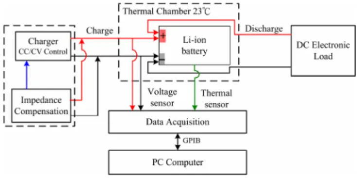
A test-bench shown in Fig. 4 was specifically designed to study charging/discharging characteristics of the Li-ion bat- tery. Based on the requirement of standard for Li-ion, the charge rate is chosen to be 1C (2.4A), discharge rate is set to be 0.55C (1.35A). Environment temperature is one of the important factor in the battery charging and discharging test.
Hence, as it can be seen from Fig. 4, a temperature-controlled thermal chamber is used to keep the environment temperature of 23°C during the test.
Fig. 4. Test-bench block diagram.
III. S
YSTEMD
ESCRIPTIONFig. 5 shows the block diagram of a Li-ion battery charger without impedance compensation. This comparator shown in Fig. 5 compares the voltage at the output of the bat- tery pack and a reference voltage. Due to the voltage drop caused by the external impedance of battery, as shown in Fig.
6, the predefined upper voltage V
MAXmay be lower to V
REG, which causes the battery charging process entering the CV stage early and in turns reducing the battery capacity. To pre- vent the battery from the effects of external impedance, an impedance compensation circuit constructed by pulsating current source, voltage detector and adder and shown in Fig.
7 is proposed in this paper to solve this problem. Here, com- pensation voltage V
BCcaused by the external impedance can be obtained by charging the battery with pulsating charge current and detected by using the voltage detector. This volt- age is used to regulate the reference voltage V
reffor the im- pedance compensation.
Fig. 5. Block diagram of a Li-ion battery charger without impedance compensation.
Fig. 6. Waveform of the transition between CC and CV stages due to voltage drop.
Fig. 7. Block diagram of a Li-ion battery charger with impedance compensation.
Fig. 8. Circuit diagram of a Buck converter.
IV. I
MPEDANCEC
OMPENSATIONC
IRCUITThe pulsating current source shown in Fig. 7 is realized by the Buck converter shown in Fig. 8. To obtaining the pul- sating charge current, the Buck converter is operated in the discontinuous current mode (DCM).
A. Principal of Impedance Compensation
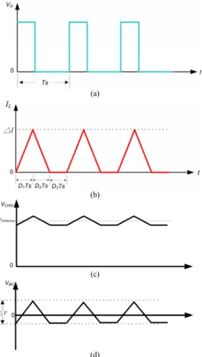
Fig. 9 shows the steady-state waveforms of buck con- verter under DCM, where (a) is switching voltage V
G, (b) is inductor current I
L, (c) is battery voltage V
CHG, and (d) is compensation voltage V
BC. Here the inductor current I
Lis the pulsating charge current used to charge the battery. On the other hand, since the high energy density characteristics of a Li-ion battery, the battery voltage V
CHGcan be the pulsating voltage shown in Fig. 9(c). Then, having the battery voltage
VCHGpass through a capacitor, the compensation voltage V
BCcan be obtained and is shown in Fig. 9(d).
(a)
(b)
(c)
(d)
Fig. 9. Steady-state waveforms of buck converter under DCM : (a) switching voltage, (b) inductor current, (c) battery voltage, and (d) compen- sation voltage.
B. Circuit Design
To generate pulsating charge current for charging the bat- tery, the peak value of output current needs to be keep con- stant for the PWM controller. That is, boundary conditions
for the DCM operation mode and the specifications for the used component play essential roles in the circuit design. For Buck converter operated in the DCM, the relationship be- tween output voltage V
oand input voltage V
iis given as
2 1
1
D D
D V V
i o
= + (1)
where V
ois output voltage, V
iis input voltage, D
1and D
2are the duty ratios when the switch in Fig. 8 turns on and turns off respectively.
For buck converter operated in DCM, the duty ratio D
1should be restricted as
i o
V
D1
<
V(2)
Referring to Fig. 9(b), the peak value of the inductor cur- rent can be determined and given as
2 1
2
D DI IL
= +
Δ (3)
where ΔI is the peak value of the inductor current and I
Lis the inductor current. For buck converter operated in DCM, the boundary condition for the value of inductor can be ex- pressed as
I T D V
L Vi o s
Δ
< ( − )
1(4)
V. E
XPERIMENTALR
ESULTSTo verify the performance of the proposed impedance compensation circuit, a pulsating current source realized by a buck converter under DCM operation mode was imple- mented. With the function of peal current control mode, PWM control IC UC3845 has been used to achieve the re- quirement of pulsating charge current. The specifications of the proposed circuit are as following:
‧ Input voltage V
i: 19V,
‧ Output voltage V
o : 9V ~ 13.5V,‧ Switching frequency f
s: 40KHz,
‧ Peak value of pulsating charge current △I : 2A,
‧ Inductor L : 25uH, and
‧ Battery : Samsung Li-ion 11.1V/2.4Ah.
Experimental waveforms of switching voltage V
Gand
pulsating charge current I
Lare shown in Fig. 10. It reveals
that a pulsating charge current with peak value of 1.9V has
been generated and used to charge the battery. Fig. 11 shows
the experimental waveforms of charge voltage V
CHGand the
inductor current I
L. It can been seen from the Fig. 11 that the
charge voltage V
CHGappears to be in the form of pulsating
due to the pulsating charging current. After filtering out the
DC level of the charge voltage V
CHG, the compensation volt-
age V
BCshown in Fig, 12 can be obtained, and then was feed-
back to the battery charger for compensate the voltage drop
caused by the external impedance.
(VG: 25 V/div, IL: 1 A/div, TS: 10 µS/div)
Fig. 10. Experimental waveforms of switching voltage and the inductor current for buck converter under DCM.
(VCHG: 5 V/div, IL: 1 A/div, TS: 10 µS/div)
Fig. 11. Experimental waveforms of charge voltage and the inductor current for buck converter under DCM.
(△V: 500 mV/div, IL: 1 A/div, TS: 10 µS/div)
Fig. 12. Experimental waveforms of compensation voltage and the inductor current for buck converter under DCM.
A Li-ion battery charger with a model of BenchMarq BQ24105 is used in the experimental test. The charger uses voltage detected type controller and its reference voltage for CC-CV transition is 2.1V. Also, the charge current during the CC stage is kept at 0.4A and the cut-off current during the CV stage is set at 0.24V. Hence, the total charge current pro- vides to the Li-ion battery is 2.4A.
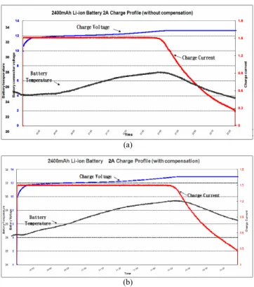
With the test-bench shown in Fig. 4, test results of the charge voltage, charge current, and battery temperature under 1.5A charge current are shown in Fig. 13, where (a) is with- out impedance compensation and (b) is with impedance com- pensation. Comparing the curves shown in Fig. 13, it reveals that charger with impedance compensation has regulated the upper voltage V
MAXfor CV stage from 12.6V to 12.9V only at the cost of increasing the maximum battery temperature from 28°C to 30°C. From Fig. 13, it also can be found that the transition time has been prolonged for more than 11 minutes, hence increasing the battery capacitor for 275mAh, that is, 11.5% effective capacitor of the battery used.
(a)
(b)
Fig. 13. Measured curves of Li-ion battery charge profile under charge current of 1.5A in 11.1V/2.4Ah battery pack (a) without impedance compensation, and (b) with impedance compensation.
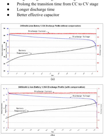
Fig. 14 shows the test results of the charge voltage, charge current, and battery temperature under 1.35A dis- charge current. Comparing the discharging time, the one for charger with impedance compensation is 10 minutes more than that for charger without impedance compensation. Esti- mating with the battery capacitor, it is 225mAh or 9.4% ef- fective capacitor of the battery used.
Table I shows the comparison of the experimental results
for charger with and without impedance compensation. Ob-
viously, it can be seen from Table 1, charger with the pro-
posed impedance compensation technique can provide the following advantages:
z
Larger charger voltage for CV stage
z
Prolong the transition time from CC to CV stage
z
Longer discharge time
z
Better effective capacitor
(a)
(b)
Fig. 14. Measured curves of Li-ion battery discharge profile under discharge current of 1.35A in 11.1V/2.4Ah battery pack (a) without impedance compensation, and (b) with impedance compensation.
TABLE I
COMPARISONS OF THE EXPERIMENTAL RESULTS FOR CHARGER WITH AND WITHOUT IMPEDANCE COMPENSATION
Design of battery Without impedance compensation
With impedance compensation
Charge time 127 Min 128 Min
Impedance detection No 160mΩ
Upper voltage 12.6 V 12.9 V
Discharge time 83 Min 93 Min
Discharge capacitor 2175 mAh 2400 mAh
Effective capacitor 90.6% 100%
VI. C
ONCLUSIONSThe paper proposed a Li-ion battery charger that adopts a pulsating current source associated with a pulsating voltage detector to dynamically estimate compensation impedance of battery. A prototype of the proposed charger was imple- mented to verify the impedance compensation function of the proposed charger. Here, the pulsating current source was re- alized by a buck converter under DCM operation mode. A
test-bench was specifically designed to study charg- ing/discharging characteristics of the Li-ion battery. Experi- mental results show that the discharge-time is extended 12%
and the overall battery capacitor is increased 10% by using the proposed charger.
R
EFERENCES[1] Yi-Hwa Liu, Jen-Chung Li, and Jen-Hao Teng, “An FPGA-based lithium-ion battery charger system,” IEEE TENCON Conference, vol. 4, pp. 435 - 438, Nov. 2004.
[2] V. L. Teofilo, L. V. Merritt, and R. P. Hollandsworth, “Advanced lithium ion battery charger,” IEEE Aerospace and Electronic Systems Magazine, vol. 12, Nov. 1997, pp. 30 – 36.
[3] Yi-Hwa Liu, Jen-Hao Teng, and Yu-Chung Lin, “Search for an optimal rapid charging pattern for lithium-ion batteries using ant colony system algorithm,” IEEE Transactions on Industrial Electronics, vol. 52, Oct.
2005, pp. 1328 – 1336.
[4] J. Lopez, M. Gonzalez, J. C. Viera, and C. Blanco, “Fast-charge in lithium-ion batteries for portable applications,” INTELEC 26th Annual International Telecommunications Energy Conference, vol.2, 19-23 Sept. 2004, pp. 19 – 24.
[5] UL Standard for Lithium Batteries, UL 1642, Third Edition, Dated April 26, this standard contains revisions through and including June 24, 1999.
[6] L. R. Chen, J. Y. Han, J. L. Jaw,. C. P. Chou, and C. S. Liu, “A Resistance-Compensated Phase-Locked Battery Charger,” IEEE Conference on Industrial Electronics and Applications, 24-26 May 2006, pp. 1 – 6.
[7] D. Salerno, and R. Korsunsky, “Practical considerations in the design of lithium-ion battery protection systems,” Applied Power Electronics Conference and Exposition, vol. 2, 15-19 Feb. 1998, pp. 700 – 707.
[8] C. H. Lin, C. Y. Hsieh, and K. H. Chen, ”A Li-Ion Battery Charger with Smooth Control Circuit (SCC) and Built-in Resistance Compensator (BRC) for Achieving Stable and Fast Charging,” IEEE Transactions on Circuits and Systems. (Accepted for future publication) [9] R. Saint-Pierre, “A dynamic voltage-compensation technique for
reducing charge time in lithium-ion batteries,” The Fifteenth Annual Battery Conference on Applications and Advances, 11-14 Jan. 2000, pp.
179 – 184.