Chapter 3
Apply Phase Modulation in Harmonic Mode-Locked Fiber Ring Laser
In this chapter, we purpose to generate the optical pulse train with higher repetition rate than modulation frequency. This paper is organized as following: Section 3-1 introduces the background of the actively mode-locked fiber ring laser. In section 3-2 we explain the physics and principle of the phase mode-locked laser from the fundamental mode-locking to further harmonic mode-locking. In section 3-3 we discuss system description. In section 3-4, we give the summary.
3-1 Introduction
At any point within the laser cavity the radiation can be described by Maxwell equations and at any point of time. There will be a change of electric and magnetic fields. So that through out the cavity there will be a variation of fields in space and in time. The spatial and temporal variations of field distributions at particular frequency are called
cavity mode. The precise definition of a cavity mode is an electric or magnetic field distribution that reproduces itself in its spatial variations and in phase as it bounces back and forth between the mirrors so that the position of wave maxima and minima do not move. In other words a standing wave pattern is set up. Because a laser is usually long and narrow, only a few modes exist in the radial direction. These are known as transverse or radial or spatial modes. But because of the large separation of the mirror error (L >> λ), many longitudinal modes which are called temporal or frequency modes can oscillate simultaneously.
In high-speed optical communication systems, an optical short pulse source with a high repetition rate is very important. The active mode-locking fiber laser is an attractive way of achieving this because it can offer a transform-limited pico- or subpico-second pulse train with very high repetition rate [25-26]. In active mode-locking lasers, in general, the obtained pulse repetition rate is equal to the modulation frequency.
But when the repetition rate is up to 20 GHz, the bandwidth bottleneck of the modulator and its driving circuits limit further increase of the repetition rate. When applying amplitude modulation, one can enhance the repetition rate by using the rational harmonic mode-locking method
with detuning the modulation frequency to a rational number of the cavity’s fundamental frequency [27-28]. However, the pulses do not have equal amplitudes so additional amplitude-equalization is required [29-31].
In a phase-modulated laser, driving the modulator at a single frequency is not expected to generate any net rational harmonic modulation.
Additional components have to be used for realizing repetition rate multiplication [32-34]. However, in this letter, we show the experimental results of repetition rate multiplication in a phase-modulated fiber laser with modulation frequency detuning, which is very similar to the rational harmonic mode-locking but has a better quality in pulse amplitude equalization.
Additive-pulse (or interferometric) mode-locking uses self-phase modulation (SPM) effects of fibers to produce a pulse which is the result of the interference between a compressed and a non-compressed one. The interference may be created with an optical device such as a coupling mirror, or a beam splitter in an interferometric cavity configuration. In the case of a beam splitter, light is divided in two parts. One, which propagates in a ”linear” branch, accumulates linear phase, whereas the other, which travels through a ”nonlinear branch” (fiber) accumulates,
intensity-dependent, nonlinear phase (SPM effect). The reflected beam at the non-fiber branch, then, interferes with the shortened, reflected pulse, from the fiber branch. The relative linear phases of the beams can be adjusted so that it creates constructive interference at the center, high intensity, portion of the pulse, and destructive interference at the lower intensity pulse tails.
High-speed mode-locked lasers have uses in applications such as telecommunications, optical sampling, and optical signal processing where low pulse train noise is a key requirement. RMS pulse-to-pulse timing jitter is proportional to the square root of the integral of residual phase noise spectral density. A roll-off is observed in mode-locked laser phase noise spectral density with a distinct corner frequency that is pushed in to lower offset frequencies with increasing cavity length for a given mode-locking frequency (harmonic mode-locking) [35]. As the corner frequency is pushed in, timing jitter contribution of the region around the corner frequency decreases, however the drawback is that supermode noise spurs at cavity frequency harmonics appear.
3-2 Phase modulation mode locking
Phase modulation mode locking is a method to produce a short
pulse train by modulation the optical phase. It can analyzed both in the time domain and the frequency domain [36].
The phase modulator can provides a periodic phase change for the pulse. If the pulsewidth is much smaller than the modulation period, the change of the optical phase produce by the phase modulator can be expressed as[37]:
...
)
( 2 2
2
0 + + +
= t
dt t d dt
t φ dφ φ
φ (3-1) where φ0 is a constant phase, and influence of φ0 on optical pulse can be neglected. The first order term
dt dφ
will influence the central frequency of the pulse and shifting magnitude of influence depends on its value. Therefore, if t ≠0
dt dφ
, the central frequency of optical pulse will be changed. In another word, the pulse will experience smaller gain and center frequency will still be changed, if t
dt dφ
is still not equal to zero.
This is unstable and will not lase. Only the pulse which pass through the PM modulator and experience maximum gain is at t
dt dφ
=0, and its every round trip is able to stable.
As regarding the second order term 2 2 2
2
t dt t
d φ η
≡ , it adds a chirp to the pulse. Also, it will affect the optical bandwidth of the pulse. The effect can be expressed in mathematics by[38]:
2 2
1 ητ
= τ
Δw (3-2) where Δw is the bandwidth of optical pulse, τ is the pulsewidth, and
2 2
dt d φ
η = the chirp parameter. In the frequency domain, we can assume that the central frequency is . When it passes through the modulator, the electric field of the pulse can be written as:
0
0
0 m m
v
)) 2 cos(
2 cos(
)
(t E vt f t
E = π +Δ π (3-3)
∑
∞∞
−
+ Δ
= E0 Jn( m)cos(2πv0 n2πfm)t (3-4)
where is modulating frequency of phase modulator, is the modulation index, is the n-th order Bessel function. If is one of the harmonic modes in the laser cavity and is N times magnitude of the fundamental harmonic frequency of the cavity, these harmonic mode ( ) will have the fixed phase relation with the ,where
,…Therefore, all these harmonic modes will have fixed phase relation. In time domain, these harmonic modes will create constructive interference at periodic time and destructive interference at other times by injection-locking [12].
fm Δm
Jn v0
fm
Kfm
v0 + v0
3 , 2 ,
1± ±
±
= K
3-2-1 Harmonic mode-locking
To generation continuous wave erbium ring laser can be actively
mode-locked by using an amplitude or phase modulator to generate pulses at the modulation frequency m
c m
f
f
f = (3-5)
nL fc c
= 2 (3-6)
where is the cavity mode-spacing frequency, c is the speed of light, L is the cavity Length and n is the refractive index of the cavity. These pulses have a round trip time of ,which is related to and the pulse width
fc
tr fc
τ as following[39],
c tr 2nl
= (3-7)
This cavity mode-spacing frequency of a typical laser cavity is of the order of 0.5~6MHz. To increase the pulse repetition rate, pulses could be produced at integer Harmonics of the cavity mode-spacing by modulating at frequency , given by where P is an integer representing the number of longitudinal modes locked, and ranges from a few hundred to tens of thousand. This is known as harmonic mode locking, these longitudinal modes with equal interval is called as supermodes, and
fm
pfp
its new round trip time shows as following[40]:
p c tr 2nL 1
⋅
= (3-8)
In 1970s, the KS (Kuizenga and Siegman) theory predicted that with amplitude mode-locking the time bandwidth product is 0.441 for a chirp-free Gaussian pulse and 0.135 for a Sech2 pulse. Furthermore, it states that the pulsewidth τ is inversely proportional to
4 1
)
(δ and(fm⋅Δf3dB)41, so that[41]
4 1 2 1
1 3
1 ⎥⎦⎤
⎢⎣⎡
⎥ ⋅
⎦
⎢ ⎤
⎣
⎡ Δ
⋅ ⋅
= δ
τ
dB
m f
K f (3-9)
Where δ is the effective single-pass amplitude modulation depth, is the 3dB gain band width of the laser cavity and K is a pulse shape-dependent constant. It is clear from this equation that with increasing modulation frequency and increasing modulation amplitude, the optical pulsewidth will be narrowed. However, though we can use this way to promote higher repetition rates, the Drawback of harmonic mode-locking is not stable for a long time.[12]
f 3dB
Δ
3-2-2 Noise source of active mode-locking
In mode-locking cavity length will not be too short for fiber laser.
Therefore there are some problem in operation of actively harmonic mode-locked fiber laser as explained. In cavity length will be affected by environmental vibration and temperature perturbation easily, the fundamental frequency is not stale. It will result in different between the modulation frequency and pulse repetition rate and degrade the mode-locking effect. The fiber laser have to be operated at the harmonic mode-locking region to achieve pulse train with a higher repetition rate. It will result in the extra supermode noise and cause the equal energy distribution, pulse dropout and power fluctuation of the output pulse.
Because the slow gain relaxation time can not equalize the individual pulse energy, harmonically mode-locked fiber laser suffer from supermode noise.
3-3 Experimentally Phase Analysis of Harmonic Mode-Locked Fiber Laser
In harmonic mode-locked fiber lasers, the optical modulator is the determining component for locking the harmonics of the resonant spectrum into a particular longitudinal mode. For this reason, it is very
important to characterize the optical modulator. With detuning the modulation frequency and polarization state, we can get the optical pulse train with repetition rate up to 50 GHz, which is eighteen times of modulation frequency 2.6 GHz.
3-3-1 Experimental Setup
The configuration of the laser is shown schematically in Fig. 3-1. and cavity length is 21.83m. The gain media of the ring laser cavity is provided by an erbium-doped fiber amplifier (Holland Electronic Corp mount, model NE6000). The output power of the EDFA is 25dBm. And there are two isolators incorporated in the erbium-doped fiber amplifier to ensure the unidirectional operation of the ring laser. A phase modulator (Crystal technology INC model.PM313P) is used as a mode-locker offering intracavity periodic loss modulation, and then driven by superimposing a sinusoidal signal with amplitude level of 17 dBm derived from a 2.69 GHz synthesizer (Leader, modal no. 3221). The laser could be forced to operate stably at harmonic frequencies of the cavity fundamental mode by detuning the modulation frequency. Because of the somewhat polarization dependent of the modulator, a polarization controller is placed before the modulator to adjust the polarization state of
the light for improving the modulation efficiency. The Power is coupled out of the cavity with a 90:10 fiber coupler, where 90﹪of the total power is used as feedback to the cavity, and 10﹪is extracted out from the cavity to measurement pulse train. The output spectral and temporal characteristics are measured with an optical spectrum analyzer (Anritsu, modal no. MS9710C) with 0.05 nm resolution, and a high speed digital sampling oscilloscope (Agilent, 86100A). When the polarization controller is correctly adjusted, then various orders of rational harmonic mode-locking can be obtained by only detuning the modulation frequency.
3-3-2 Experimental of Results
In this section, we use the fiber ring cavity to get pulse output and analyze the result of detuning the modulation frequency. We have tried to adjust the modulation frequency to measurement the change of pulse train.
When we change modulation frequency from RF generator to observe RMS jitter, repetition rate, and rise time. To obtain higher repetition rate the rational harmonic mode-locking (RHML) technique should be used.
The phenomenon of RHML is observed when the modulation frequency is changed.
3-3-2-1 5 GHz Pulse Train Generation
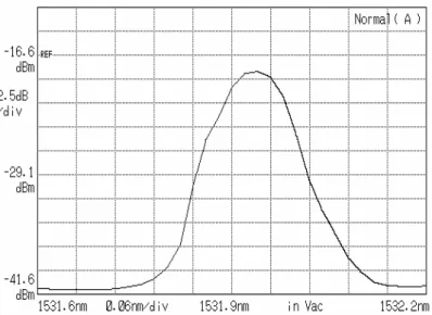
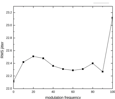
Fig. 3-2 shows the output pulse train of the rational harmonic mode-locked laser when the modulation frequency is set to 2.49788842 GHz. The pulse period is 200 ps which correspond to a repetition rate of 5 GHz and use optical spectrum amplifier to get wavelength as shown in Fig. 3-3. We also measure the repetition rate in Fig. 3-4 and RMS jitter in Fig. 3-5 by changing modulation frequency. We observe the RMS jitter to find the maximum value of 23.42 ps and minimum value of 22.12ps. We also change the modulation frequency to observe the rise time in Fig. 3-6 which find the maximum value of 12.63 ps and minimum value of 12.12 ps.
3-3-2-2 10 GHz Pulse Train Generation
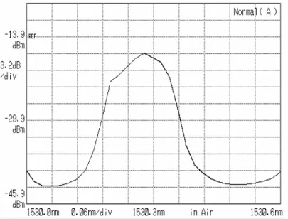
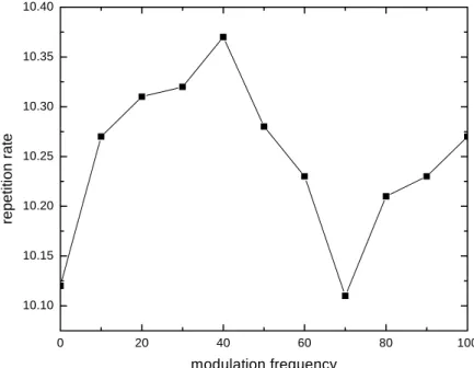
Fig. 3-7 shows the output pulse train of the rational harmonic mode-locked laser when the modulation frequency is set to 2.48766343 GHz. The pulse period is 100 ps which correspond to a repetition rate of 10 GHz and use optical spectrum amplifier to get wavelength as show as in Fig. 3-8. We also measure the repetition rate in Fig. 3-9 and RMS jitter in Fig. 3-10 by change modulation frequency. We observe the RMS jitter to find the maximum value of 17.09 ps and minimum value of 15.62 ps.
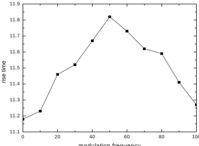
We also change the modulation frequency to observe rise time in Fig.
3-11 which find the maximum value of 11.82 ps and minimum value of 11.18 ps.
3-3-2-3 20 GHz Pulse Train Generation
Fig. 3-12 shows the output pulse train of the rational harmonic mode-locked laser when the modulation frequency is set to2.49728146 GHz. The pulse period is 50 ps which correspond to a repetition rate of 20 GHz and use optical spectrum amplifier to get wavelength in Fig.
3-13 . We also measure the repetition rate in Fig. 3-14 and RMS jitter in Fig. 3-15 by change modulation frequency. We observe the RMS jitter to find the maximum value of 15.21 ps and minimum value of 14.53 ps. We also change the modulation frequency to observe rise time in Fig. 3-16 which find the maximum value of 10.82 ps and minimum value of 10.17ps.
3-3-2-4 50 GHz Pulse Train Generation
Fig. 3-17 shows the output pulse train of the rational harmonic mode-locked laser when the modulation frequency is set to 2.49728146 GHz. The pulse period is 20 ps which correspond to a repetition rate of 5- GHz and use optical spectrum amplifier to get wavelength in Fig. 3-18.
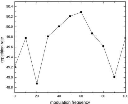
We also measure the repetition rate in Fig. 3-19 and RMS jitter in Fig.
3-20 by change modulation frequency. We observe the RMS jitter to find the maximum value of 12.86 ps and minimum value of11.48 ps. We also change the modulation frequency to observe rise time in Fig. 3-21 which find the maximum value of 9.12 ps and minimum value of 8.42 ps.
3-4 Summary
In this chapter, we have demonstrated a new structure of using phase modulated fiber ring laser. We have trigger the mode locked laser of repetition rate of 5Gb/s, 10Gb/s, 20Gb/s, 50Gb/s with modulation frequency of 2.49788842 GHz, 2.48766343GHZ, 2.49728146 GHz, 2.49728146 GHz. In the above experiment, we have known repetition rate, RMS jitter and rise time changing with modulation.
PM
RF Synthesizer PC
90:10 coupler
Oscilloscope
Optical spectrum analyzer EDFA module
Fig. 3-1 The structure of a phase-modulated
200 ps/div 6mV/div
Fig. 3-2 The 5 GHz of PM mode lock with modulation frequency of 2.49788842 GHz
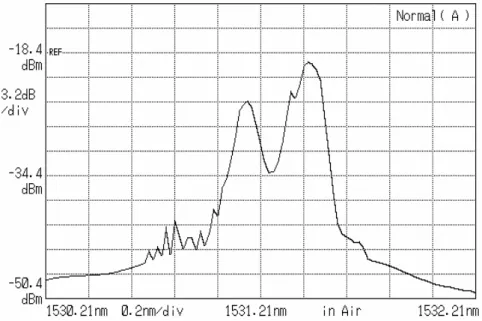
Fig. 3-3 The 5GHz lasing spectrum with modulation frequency of 2.49788842 GHz
0 20 40 60 80 100
5.00 5.05 5.10 5.15 5.20 5.25 5.30 5.35 5.40 5.45
repetition rate
modulation frequency
Fig. 3-4 Change of repetition rate by detuning modulation frequency
0 20 40 60 80 100 22.0
22.2 22.4 22.6 22.8 23.0 23.2
RMS jitter
modulation frequency
B
Fig. 3-5 Variation of RMS jitter by detuning modulation frequency
0 20 40 60 80 100
12.1 12.2 12.3 12.4 12.5 12.6 12.7
rise time
modulation frequency
Fig. 3-6 Variation of rise time by detuning modulation frequency
100 ps/div 6mV/div
Fig. 3-7 The 10 GHz of PM mode lock with modulation frequency of 2.48766343 GHz
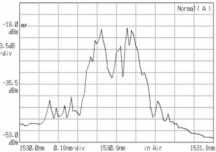
Fig. 3-8 The 10GHz lasing spectrum with modulation frequency of 2.48766343 GHz
0 20 40 60 80 100 10.10
10.15 10.20 10.25 10.30 10.35 10.40
repetition rate
modulation frequency
Fig. 3-9 Change of repetition rate by detuning modulation frequency
0 20 40 60 80 100
15.6 15.8 16.0 16.2 16.4 16.6 16.8 17.0 17.2
RMS jitter
modulation frequency
Fig. 3-10 Variation of RMS jitter by detuning modulation frequency
0 20 40 60 80 100 11.1
11.2 11.3 11.4 11.5 11.6 11.7 11.8 11.9
rise time
m odulation frequency
Fig. 3-11 Variation of rise time by detuning modulation frequency
6mV/div
50 ps/div
Fig. 3-12 The 20 GHz of PM mode lock with modulation frequency of 2.49728146 GHz
Fig. 3-13 The 20GHz lasing spectrum with modulation frequency of 2.49788842 GHz
0 20 40 60 80 100
19.7 19.8 19.9 20.0 20.1 20.2 20.3 20.4 20.5
repetition rate
modulation frequency
Fig. 3-14 Change of repetition rate by detuning modulation frequency
0 20 40 60 80 100 14.5
14.6 14.7 14.8 14.9 15.0 15.1 15.2 15.3
RMS jitter
modulation frequency
0 20 40 60 80 100
10.1 10.2 10.3 10.4 10.5 10.6 10.7 10.8 10.9
rise time
modulation frequency
Fig. 3-15 Variation of RMS jitter by detuning modulation frequency
Fig. 3-16 Variation of rise time by detuning modulation frequency
20 ps/div 6mV/div
Fig. 3-17 The 50 GHz of PM mode lock with modulation frequency of 2.49728146 GHz
Fig. 3-18 The 50GHz lasing spectrum with modulation frequency of 2.49788842 GHz
0 20 40 60 80 100 48.8
49.0 49.2 49.4 49.6 49.8 50.0 50.2 50.4
repetition rate
modulation frequency
Fig. 3-19 Change of repetition rate by detuning modulation frequency
0 20 40 60 80 100
11.4 11.6 11.8 12.0 12.2 12.4 12.6 12.8 13.0
RMS jitter
modulation frequency
Fig. 3-20 Variation of RMS jitter by detuning modulation frequency
0 20 40 60 80 100 8.4
8.5 8.6 8.7 8.8 8.9 9.0 9.1 9.2
rise time
modulation frequency
Fig. 3-21 Variation of rise time by detuning modulation frequency