行政院國家科學委員會專題研究計畫 成果報告
工作於一般社會環境下之智慧型機器人界面研究 研究成果報告(精簡版)
計 畫 類 別 : 個別型
計 畫 編 號 : NSC 99-2221-E-011-133-
執 行 期 間 : 99 年 08 月 01 日至 100 年 07 月 31 日 執 行 單 位 : 國立臺灣科技大學電機工程系
計 畫 主 持 人 : 蘇順豐
計畫參與人員: 學士級-專任助理人員:邱詩評
碩士班研究生-兼任助理人員:莊崴丞 碩士班研究生-兼任助理人員:詹彧彬 碩士班研究生-兼任助理人員:陳偉明 碩士班研究生-兼任助理人員:李謹安 博士班研究生-兼任助理人員:葉人瑋 博士班研究生-兼任助理人員:劉岳翔
處 理 方 式 : 本計畫可公開查詢
中 華 民 國 100 年 10 月 24 日
1
工作於一般社會環境下之智慧型機器人界面研究
Study on Intelligent Robot Interface for Working in an Ordinary Society
計劃編號:NSC 99-2221-E-011-133- 執行期間:99 年 08 月 1 日至 100 年 07 月 31 日 計劃主持人:蘇順豐 國立臺灣科技大學電機系教授 參與人員:葉人瑋、劉岳翔、莊崴丞、詹彧彬、陳偉明、李謹安
電子信箱:[email protected] 執行機構:國立台灣科技大學電機學系
Abstract
In this study, the architecture of smart systems with integration of environment and equipment is developed to assist human living. This system at least must be able to manage a home and to respond to humans. We hope the designed architecture can truly integrate formations and objects in the whole framework of smart systems. A mathematical model is extended from Petri nets and is defined as Home Petri net to simplify the process of building systems. Parallel process is considered as the fundamental concept of Home Petri net once operation.
All of enabling procedures will be got and the so-called better conflict decision method is proposed to choose the better one. Home Petri net can be viewed as the object oriented design and the concept of basic net is used to produce the entire system through the links among entities. It makes different systems have a rule to connect with each other so that it can reduce the possibility of deadlock occurrence. This study proposed a simple mathematical method to solve the deadlock and to remove certain part of the basic net for deleted objects and the system can operate normally.
Keywords: Smart system, Home Petri net, Context- Aware Petri net, parallel process, better conflict decision method, marking update rule, optional branch net, deadlock, sensor-embedded houses.
I. Introduction
A smart system must consider many devices that are integrated into a place or home as considered in this study, with the capability of communication with the system. A smart system also requires the system to act smartly, where smartly means some actions can be automatically triggered and some system actions can be smartly selected based on users’ preference or habits [1-7]. Smart system or more precisely smart home has been explored in many different aspects.
Each research aspect with its special theme represents a special purpose in achieving some capabilities like Context-Aware or Petri Nets [8-10].
A Smart Home System is a service platform [15]
to support users for monitoring, controlling and sending commands to smart objects in a smart house.
for users. Such a smart home system needs an integrated system and must connect many sensors
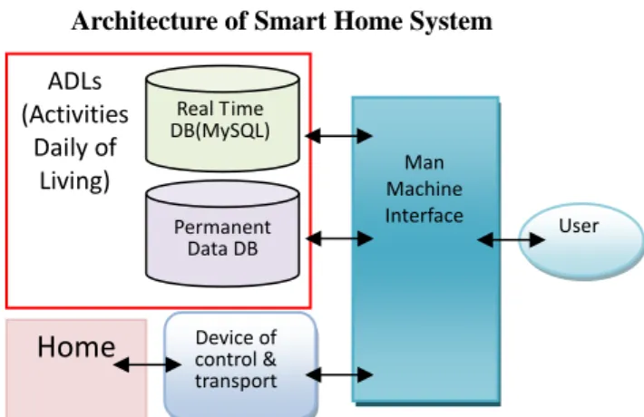
and devices. It also needs to include many functions for serving users and transporting signal to/from devices. A framework of such an integrated system is proposed in our study.. The proposed framework for smart home systems is shown in Figure 1.
Architecture of Smart Home System
Figure 1 Basic framework of the proposed system
II. System Description
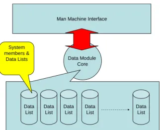
A designer may need to set description of the building (or house), to get smart objects, to create family related data, to connect devices and to create module data in the system to represent those real objects. All real objects data are store in PDDB. As shown in Figure 2, when the system is initialized, those data representing real objects and their status are created in the Data Module Core. The building data is a part of PDDB. In the smart home system frame, the house data are for a floor as a home not a building. However, a building or house is not just one floor. Thus, different floors must have different datum points so that when objects in different floors or events occur in multiple floors, the system can get different answers because different datum points are employed to distinguish those situations. In addition to the datum points of floors, In order to capture all information in a building, a datum point for the building is also considered in our implementation.
User Man
Machine Interface Real Time
DB(MySQL)
Permanent Data DB
ADLs (Activities
Daily of Living)
Device of control &
transport
Home
2
Data Module Core Man Machine Interface
Data List
Data List Data
List
Data List Data
List System
members &
Data Lists
Figure 2 Data Module Core
The Man-Machine Interface (MMI) is designed to support users to complete all functions what they want to do [16]. The Database of the smart system records those about Activities Daily of Living (ADLs) and stores all event data of the house and the family, All data are separated into two parts, Real Time Database (RTDB) and Permanent Data Database (PDDB). The MMI connects all of smart objects and provides commands via the device of control &
transport so that users can monitor values and status of smart objects through MMI. When users send commands to control devices through MMI, MMI will record the message into the database. The system can create a user operating history to assist the designer or the system manager in analyzing users’ behavior. According to these data, the designer can improve the system or change some settings.
All of data in PDDB can be edited by users. Users can edit the data through the editor of MMI. The functions of editor include building, objects, families, etc. The Editor will be linked to data module core so as to edit or to rewrite the client data, and if user commands can satisfy some conditions, the system returns the client data to PDDB. Contrary to PDDB, RTDB consists of data of time events. Users have no requirement of changing data in RTDB.
As shown in Figure 1, the system consists of two main parts. The first one is MMI (Man Machine Interface), which deals with all requirements for users and shows all status of the system for monitoring. The other one is the Data Module Core, which stores all client data of the system. In the system initializing step, the database is queried to create client data and a frame of the core. The main system is a data transport, which deals with and saves data in the center. All of the reactions and events in Smart Home System are dealt with by the Data Module Core and stored data in Core. MMI is just a tool for users to links to Data Module Core and commands. In Data Module Core, all of working rules are functions of those system members and data lists except commands given by users. Users can
save personal setting in core through MMI.
The smart objects in the real world are symbols of client data in the main system and may consist of many fundamental properties of real objects and the links to corresponding data. In the system initializing step, the system creates those smart objects according to data stored in PDDB. But when those client data are created, those corresponding links are not created yet. It needs another step to create those links and this step is included in the system initializing step.
Smart objects, in addition to those fundamental data, contain values to define statuses of real objects. The data link list is named object modules to model the frame, fundamental status, value status and meaning of every type of smart objects. It also records some reaction procedure codes.
III. Data Description
Since the purpose is to build a system for human, it is required to have data related to human. The composition of human data is illustrated in Figure 3.
A basic attribute for human data is the corresponding authority data, which include log name and authority level [17]. From human data, the system can find individual lists and active state. Individual lists like a memorandum of personal data and cannot affect the program just a record for users shown on MMI.
Active state stores properties of human state and cannot be edited or saw by users. Authority data save those information about login and authority levels. A human data can combine with an authority data or exists independently. Those data about human are not connected with any system member except that active state connects with operating units.
Figure 3 Data about human
Permanent Data Database stores those data that are not changed automatically. They can only be changed by users or designers. It can be viewed as a fundamental framework database The data in this database will be transformed to be client data just at the system initializing step. As shown in Figure 4, the framework of PDDB is to partition data by labels
Human Authority
Active State
Connect In house Floor Coordinate ...
ID Name Sex RFID Num.
...
Log Name Password Authority Level Individual list ...
Madison list Schedule ...
3 instead of by tables.
Figure 4 Labels and Data
In our implementation, start labels also include the information about types. Thus, different start labels represent different data types. The system can know what kind of data based on its start label. The end label is an end symbol of a set of data. The system can get the length of data according to its start label.
After getting the data that satisfy the length of the type, the system awaits the end label until getting it or it is Eof. And unlike normal databases, data are linked by keys. In our system, a method similar to the binary tree is employed. In some design, a binary tree can link two points. The one is the same level point, and the other called sub item is the point to the next level. In this design, system recognizes the relationship of levels by orders and types.
Real Time Database (RTDB) is a part of ADLs database. In RTDB, a time item exists in all data.
What the action is caused, who, where, and all active values will be recorded in RTDB with time. The framework of RTDB is simple. It is a table frame database. And it does not link directly to PDDB or client data in Data Module Core, so its complexity is very low.
IV. Petri Net Based Smart Home System
Petri net is a useful and visible mathematical model with parallel and discreet behavior [11-13].
Especially in discrete event systems, it presents a way of reducing the process time for analysis in logical algorithm [14]. With parallel and distribution of dynamic simulation capability for the development of management and engineering, Petri nets can be used in many applications and play an important role in achieving their success. In this study, we adopt Petri net to manage smart objects in software simulation. The smart objects can be smart furniture and sensors and are used to collect data and to respond to users’ commands.
In this study, Petri net is used to model the dynamic behavior occurring in the home considered.
The advantage of using Petri nets is that it has the ability to simplify the complexity of processes with the use of places and transitions [18,20,21]. In order to construct Home Petri net (HPN), the concept of the Context-Aware Petri net is adopted into our design. The fundamental idea about Home Petri net is that the entire system is composed of basic nets.
This basic net has specific tasks and complete
functions such as fusion and execution. In addition, the basic net is allowed to connect with other basic nets in serial or in parallel but it cannot affect the fundamental architecture. Thus, the HPN is a kind of object oriented architecture in terms of basic nets.
Therefore, one of properties of HPN is two layers architecture which let the different basic net connect with each other standardized.
HPN is to define links among basic nets and there are two important properties in HPN. The complete scenario is composed of series settings given by user’s selections. The whole net can be separated into two parts: the fundamental structure and the optional branch net. The fundamental structure is the core of the basic net. It records the main process of a single event. The connection of the fundamental structure is fixed but still allows user to select from those build-in procedures. Also, the fundamental structure can analyze the source of data and send commands to output devices. Thus, it can be viewed as a dependent procedure or an independent object. In some cases, it may be required to fuse related sensors or data so that the basic net can compare data from different resources. In order to let the user define more diverse objects, the optional branch nets are connected to other basic nets in parallel. The branch net is connected with a fixed number of transitions in the fundamental structure. If a branch net does not link to any basic net, it will be removed to ensure the entire Petri net to be safe.
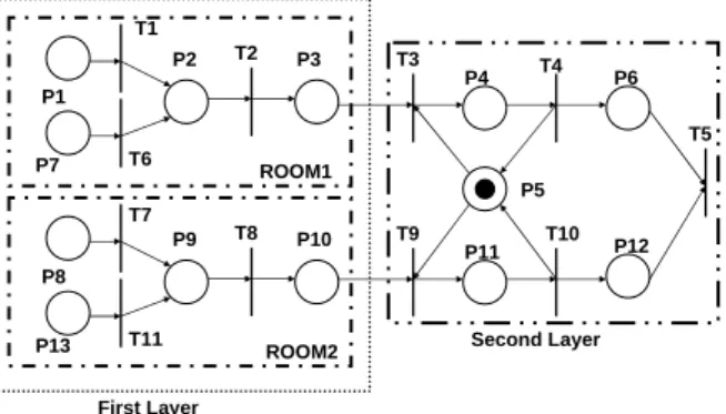
Figure 5 is the diagram of the proposed two layers architecture for HPN. Such two-layer architecture makes the basic net connect in series and it is an important property for our system. The first layer will be fired by sensors or events and the second layer gets transition from its previous layer. In fact, the second layer net can be said to be advance processes which can be designed by users.
P1
P7
P2 P3
T1 T2
T6
P8
P13
P9 P10
T7 T8
T11
P4
P5
T3 T4
P11 T9
P6
P12 T5
T10 ROOM1
ROOM2 First Layer
Second Layer
Figure 5 The connection of the two layer architecture
In this study, four kinds of places are defined and used to represent the status of environment. Source is used to represent a sensor. It saves the related data and information about a sensor. Every sensor has its own place [22,23]. Buffer is a register during the process. The status or numeral data is stored in it.
Ack is used to indicate which sensor can be released.
End label
‧‧‧
Start
label Data1 Data2 DataN
4 The sensor transmits its data and must be locked at this time. After the data has been sent, the source is then released. Thus, Ack is to indicate the released sensor and it always connects to the corresponding transition with communication protocol. Outcome is a kind of place that we define as the operating result.
It stores the message after the source data has been operated. It contains the command of the controllable object or other status with the use of contexts.
Besides, it can be the source of other nets depending on our demand. While one net completed and got a suitable result, the information is preserved in an Ack place. This will become the source for a new net, which is defined as the second layer.
Based our definition, another sensor can be added into the Petri net as shown in Figure 6. It can be adapted to increase branch nets and it can also be connected to multiple Petri nets. If the branch does not exit, it can be created. If the net already exits, the newer arc between them is created. For removing a existed sensor in the system, there are two steps. One is to remove the connection. If a specific sensor is required to be removed from an event and the net still have the other available resource, the arc between them can be deleted so that the other part of the net is still there. On the other hand, if the link does not be used, then is should be removed to avoid deadlock [24-29]. The flow chart is shown in Figure 7.
Figure 6 The basic connection of the Petri net without circulation
Select the specific event
Remove Source from this subnet
Use the deadlock prevention module
Check the deadlock
Remove the entire parameter from database
Reload the Petri net from the database
Figure 7 Removal of an event from the Petri net
In this study, Ethernet is employed to stand for an application with cross-platform. According to this idea, a system is implemented to simulate the
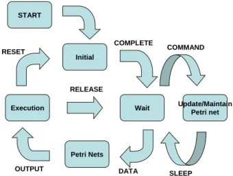
behavior of dynamic Petri net [19]. Assume that all of the sensors and controllable objects are connected to a specific device. The complete process of this system consists of the following modes:
I. Initial mode: Initialize the system;
II. Wait mode: Wait for events occurring;
III. Petri net mode: Compute the source data and determine the replying event by Petri net;
IV. Execution mode: According to the result of computing from previous state, the task is executed.
V. Update/Maintenance mode: This model is used to change or check the Petri net for safety. The method is illustrated in the previous section and the Petri net can be a dynamic system.
The complete operation is shown in Figure 8.
Initial
Wait
Petri Nets Execution
START
RELEASE RESET
OUTPUT DATA
COMPLETE
Update/Maintain Petri net COMMAND
SLEEP
Figure 8 The relationship among five models
V. Conclusions
In this study, the architecture of smart systems with integration of environment and equipment is developed to assist human living. This approach provides a simple framework of hardware for smart home systems, and it is easy to integrate a lot of different devices by unifying formats of symbol data and devices. This system consider the concept of a whole building instead of traditional one floor design, and this design makes system capable of recording and represent more extensive space than normal design does. Special editors are created in MMI of the smart home system and can be employed to assist users to change setting and content data easily. And we also proposed a framework of database for this smart home system which is based on label structure rather than table structure. This structure make us can recognize the data type easily.
For making the smart home system work smoothly, the Home Petri net (HPN) is proposed to construct the entire system. HPN can have parallel processes and also needs some methods to maintain the integrity of the system. The proposed system has the capability of reducing the possibility of deadlock occurrence. Besides, two-layer architecture of HPN
Source Sensor
Procedure 1 Gate
Buffer 1 Outcome Ack
Procedure 2 Collection
Buffer 2
Procedure 3
Fusion Procedure 4 Execution
S1 O1 A1
5 is proposed to make the system more diverse. From those developments, the research about smart home can be integrated with more methods and technologies. Hopefully, a more complete and smarter system can be obtained.
References
[1] R. Lutolf, “Smart home concept and the integration of energy meters into a home based system,” Seventh International Conference on Metering Apparatus and Tariffs for Electricity Supply, pp.277-278, 1992.
[2] L. Jiang, D.-Y. Liu, and B. Yang, “Smart home research,” Proceedings of 2004 International Conference on Machine Learning and Cybernetics, Vol.
2, pp.659-663, 2004.
[3] Y. Liu, “Design of the smart home based on embedded system,” 7th International Conference on Computer Aided Industrial Design and Conceptual Design, pp.1 – 3, 2006.
[4] T. Yamazaki, “Beyond the Smart Home,” International Conference on Hybrid Information Technology, Vol. 2, pp.350-355, 2006.
[5] B. Ando, “An environmental sensor providing home light classification to blind people,” Proceedings of the 2005 IEEE Conference on Instrumentation and Measurement Technology, Vol. 2, pp.1438-1442, 2005.
[6] A. Rosendahl and G. Botterweck, “Mobile home automation - Merging mobile value added services and home automation technologies,” 2007. International Conference on Management of Mobile Business, pp.31-31, 2007.
[7] C.-L. Wu, W.-C. Wang, and L.-C. Fu, “Mobile agent based integrated control architecture for home automation system,” Proceedings of 2004 IEEE/RSJ International Conference on Intelligent Robots and Systems, Vol. 4, pp.3668-3673, 2004.
[8] J.-S. Cho, S.-H. Park, Y.-J. Han, and T.-M. Chung,
“CAISMS: A context-aware integrated security management system for smart home,” 9th International Conference on Advanced Communication Technology, Vol. 1, pp.531-536, 2007.
[9] J. Park, M. Moon, S. Hwang, and K. Yeom, “CASS: A context-aware simulation system for smart home,” 5th ACIS International Conference on Software Engineering Research, Management & Applications, pp.461-467, 2007.
[10] T. Matsuura, K. Hisazumi, T. Kitasuka, T. Nakanishi, and A. Fukuda, “UDSS: Sensor device for context awareness in home network,” Fourth International Conference on Networked Sensing Systems, pp.196-200, 2007.
[11] T. Murata, “Petri nets: properties, analysis and applications,” Proceeding of the IEEE, vol. 77 no. 4, April 1989.
[12] J. L. Peterson, Petri Net Theory and the Modeling of Systems, Englewood Cliffs, NJ: Prentice-Hall, 1981 [13] Y. Dong, B. Zhang and K. Dong, “An integrated PLC
smart home system in pervasive computing,” 7th International Conference on Ubiquitous Intelligence and Computing, pp.288-291, 2010.
[14] C. A. Petri, Communication with Automata, Technical Report RACD-TR-65-377, Rome Air Dev. Center, New York, 1996.
[15] W.-H. Liau, C.-L. Wu, and L.-C. Fu, “Inhabitants tracking system in a cluttered home environment via
floor load sensors,” IEEE Transactions on Automation Science and Engineering, Vol. 5, no. 1, pp.10-20, 2008.
[16] J.M. Reyes Alamo, and J. Wong, “Service-oriented middleware for smart home applications,” 2008. IEEE Conference on Wireless Hive Networks, pp.1-4, 2008.
[17] B.H. McNally, “An approach to human behavior modeling in an air force simulation,” 2005 Proceedings of the Winter Simulation Conference, pp.5, 2005.
[18] M. Yan, Z. Li, N. Wei, and M. Zhao, “A deadlock prevention policy for a class of Petri nets PMR S 3,”
Journal of Information Science and Engineering, Vol.
25, pp 167-183, 2009.
[19] M. H. Shwehdi and A. Z. Khan, “A power line data communication interface using spread spectrum technology in home automation,” IEEE Transaction on Power Delivery, Vol. 11, pp. 1232-1237, Jul 1996.
[20] C. Brom and A. Abonyi, “Petri nets for game plot,” in Proc. AISBA Artificial Intelle\igence and Simulation Behavior Convention, Bristol, U.K., Vol. 3, pp. 6-13, 2006.
[21] Y.-S. Lee and S.-B. Cjo, “Exploiting mobile contexts for Petri-net to generate a story in cartoons,” Appl.
Intell., Vol. 34, No. 1, pp. 1-18, 2010.
[22] Y.-S. Lee and S.-B. Cho, “Context-aware Petri Net for dynamic procedural content generation in role-playing game,” IEEE Computational Intelligence, Vol. 6, No. 2, pp. 16-25, May 2011.
[23] C. B. Yang, “Reducing conflict resolution time for solving graph problems in broadcast communications,” Information Processing Letters, Vol.
40, pp.295-302, 1991.
[24] M. Yan, Z. Li, N. Wei, and M. Zhao, “A deadlock prevention policy for a class of Petri nets” Journal of Information Science and Engineering, Vol. 25, pp 167-183, 2009.
[25] Z. Banaszak and B. H. Krogh, “Deadlock avoidance in flexible manufacturing system with concurrently competing process flows,” IEEE Transactions on Robotics and Automation, Vol. 6, pp. 720-734, 1990.
[26] F. S. Hsien and S. C. Chang, “Dispatching-driven deadlock avoidance controller synthesis for flexible manufacturing systems,“ IEEE Transaction on Robotics and Automation, Vol. 10, pp. 196-209, 1994.
[27] J. Park and S. A. Reveliotis, “Deadlock avoidance in sequential resource allocation systems with multiple resource acquisitions and flexible routings,” IEEE Transactions on Robotics and Automation, Vol. 46, pp.
1572-1583, 2001.
[28] K. Y. Xing, B. S. Hu, and H. X. Chen, “Deadlock avoidance policy for Petri-net modeling of flexible manufacturing systems with shared resources,” IEEE Transactions on Automatic Control, Vol. 42, pp.
289-295, 1996.
[29] H. Zandong and G. Lee, “Application of Petri nets for deadlock analysis and avoidance in flexible manufacturing systems,” The International Journal of Advanced Manufacturing Technology, Vol.25, Iss.7-8, pp.735, 2005.
國科會補助計畫衍生研發成果推廣資料表
日期:2011/10/21
國科會補助計畫
計畫名稱: 工作於一般社會環境下之智慧型機器人界面研究 計畫主持人: 蘇順豐
計畫編號: 99-2221-E-011-133- 學門領域: 智慧型機器人
無研發成果推廣資料
99 年度專題研究計畫研究成果彙整表
計畫主持人:蘇順豐 計畫編號:99-2221-E-011-133- 計畫名稱:工作於一般社會環境下之智慧型機器人界面研究
量化
成果項目 實際已達成
數(被接受 或已發表)
預期總達成 數(含實際已
達成數)
本計畫實 際貢獻百
分比
單位
備 註 ( 質 化 說 明:如 數 個 計 畫 共 同 成 果、成 果 列 為 該 期 刊 之 封 面 故 事 ...
等)
期刊論文 0 0 100%
研究報告/技術報告 2 2 100%
研討會論文 1 1 100%
論文著作 篇
專書 0 0 100%
申請中件數 0 0 100%
專利 已獲得件數 0 0 100% 件
件數 0 0 100% 件
技術移轉
權利金 0 0 100% 千元
碩士生 2 4 100%
博士生 2 2 100%
博士後研究員 0 0 100%
國內
參與計畫人力
(本國籍)
專任助理 1 1 100%
人次
期刊論文 0 1 100%
研究報告/技術報告 0 0 100%
研討會論文 0 1 100%
論文著作 篇
專書 0 0 100% 章/本
申請中件數 0 0 100%
專利 已獲得件數 0 0 100% 件
件數 0 0 100% 件
技術移轉
權利金 0 0 100% 千元
碩士生 0 0 100%
博士生 0 0 100%
博士後研究員 0 0 100%
國外
參與計畫人力
(外國籍)
專任助理 0 0 100%
人次
其他成果
(
無法以量化表達之成 果如辦理學術活動、獲 得獎項、重要國際合 作、研究成果國際影響 力及其他協助產業技 術發展之具體效益事 項等,請以文字敘述填 列。)無
成果項目 量化 名稱或內容性質簡述
測驗工具(含質性與量性) 0
課程/模組 0
電腦及網路系統或工具 0
教材 0
舉辦之活動/競賽 0
研討會/工作坊 0
電子報、網站 0
科 教 處 計 畫 加 填 項
目 計畫成果推廣之參與(閱聽)人數 0
國科會補助專題研究計畫成果報告自評表
請就研究內容與原計畫相符程度、達成預期目標情況、研究成果之學術或應用價 值(簡要敘述成果所代表之意義、價值、影響或進一步發展之可能性) 、是否適 合在學術期刊發表或申請專利、主要發現或其他有關價值等,作一綜合評估。
1. 請就研究內容與原計畫相符程度、達成預期目標情況作一綜合評估
■達成目標
□未達成目標(請說明,以 100 字為限)
□實驗失敗
□因故實驗中斷
□其他原因 說明:
2. 研究成果在學術期刊發表或申請專利等情形:
論文:□已發表 □未發表之文稿 ■撰寫中 □無 專利:□已獲得 □申請中 ■無
技轉:□已技轉 □洽談中 ■無 其他:(以 100 字為限)
3. 請依學術成就、技術創新、社會影響等方面,評估研究成果之學術或應用價 值(簡要敘述成果所代表之意義、價值、影響或進一步發展之可能性)(以 500 字為限)
在此一研究中,我們開發了一能結合環境及設備的智慧型系統的架構以協助人類來使用機 器。此一系統至少要能適切的管理所有資源與信息並對使用者恰當的反應。我們也利用以 派屈網路為基礎的數學模式來提出所謂的居家派屈網路來使環境系統的建立與維持更容 易。所建構系統可以用於未來的系統整合及功能測試,使 智慧型系統能確實在一般家庭 被使用。