行政院國家科學委員會專題研究計畫 成果報告
分散式虛擬環境之同步機制應用於即時遠程操作系統之研 究
研究成果報告(精簡版)
計 畫 類 別 : 個別型
計 畫 編 號 : NSC 95-2221-E-011-127-
執 行 期 間 : 95 年 08 月 01 日至 96 年 09 月 30 日 執 行 單 位 : 國立臺灣科技大學資訊工程系
計 畫 主 持 人 : 鄧惟中
計畫參與人員: 碩士班研究生-兼任助理:游智崴、葉致宏
報 告 附 件 : 出席國際會議研究心得報告及發表論文
處 理 方 式 : 本計畫可公開查詢
中 華 民 國 96 年 12 月 26 日
行政院國家科學委員會補助專題研究計畫 □ ˇ 成 果 報 告
□期中進度報告 分散式虛擬環境之同步機制應用於即時遠程操作系統之研究
計畫類別:□ˇ 個別型計畫 □ 整合型計畫 計畫編號:NSC95-2221-E-011-127-
執行期間: 95 年 8 月 1 日至 96 年 9 月 30 日
計畫主持人:鄧惟中 共同主持人:
計畫參與人員: 游智崴、葉致宏
成果報告類型(依經費核定清單規定繳交):□ˇ精簡報告 □完整報告
本成果報告包括以下應繳交之附件:
□赴國外出差或研習心得報告一份
□赴大陸地區出差或研習心得報告一份
□ˇ出席國際學術會議心得報告及發表之論文各一份
□國際合作研究計畫國外研究報告書一份
處理方式:除產學合作研究計畫、提升產業技術及人才培育研究計畫、
列管計畫及下列情形者外,得立即公開查詢
□涉及專利或其他智慧財產權,□一年□二年後可公開查詢 執行單位:國立台灣科技大學
中 華 民 國 96 年 12 月 25 日
摘要
近年來,利用網際網路來傳送資訊的遠程操作系統應用逐漸增加。相對於專屬線路,網際 網路連線可以有效降低設置成本,並可提供彈性且大幅度的遙控距離。同時由於操作者和 機器人之間不再由專屬線路連結,因此兩者之間由一對一的對應關係轉變為更富彈性的多 對多。然而網際網路的變動傳輸延遲造成即時遠程操作系統必須面對不同性質且不同延遲 資訊的同步與顯示問題。另一方面,分散式虛擬環境由於其系統架構及目的,因此同樣面 對變動傳輸延遲之即時同步顯示問題。由於分散式虛擬環境領域已提出數個較成熟的方 法,本計畫擬修改現有之分散式虛擬環境同步機制以套用於即時遠程操作系統,預計將可 大幅改進即時遠程操作系統在網路傳輸議題上的成熟度。本計劃的主要貢獻將在於各種同 步機制的併用與修改後的同步機制如何以預測顯示技術回饋給操作者等議題上。
本計畫成功實作local lag, PHBDR與delay decorator三項技術,並實際應用於網路遙控機器 人系統上。文獻提及之local lag為處理各自獨立之事件所開發出來的技術,然而由於各種感 測器的回饋資訊為連續的資料流,因此我們自行開發出計算平均延遲的方式來實作。
Abstract
It ‘s been observed that teleoperation systems have started to switch their proprietary communication channel to local network or Internet in recent years. Internet provides low cost, flexible and long-range communication, yet the property of network also changes the relationship between operator site and teleoperator site from one-to-one mapping to much flexible more-to-more mapping. However, network jitter also changes traditional fixed transmission delay unto intractable variant time delay. Since there are usually more than one kind of feedback information in teleoperation, we need to synchronize all kind of information to provide a consistent interface, with which the time delay becomes larger even in real-time teleoperation systems. On the other hand, distributed virtual environment systems already faced similar problem since they are born, and several sophisticated approaches could be found in literature to compensate the problem of variant time delay. In this proposal we plan to modify current synchronization mechanisms of distributed virtual environment field and apply them to real-time teleoperation systems. It ‘s been expected that much matured network transmission technologies would be developed for real-time teleoperation systems. The main contribution of this proposal would be on the issues of how to combining several synchronization and how to present synthetic feedback with predictive display technology.
中文關鍵詞: 行動機器人、遠端遙控、預測顯示、人機介面
Keyword: mobile robot, teleoperation, PHBDR, local lag, delay decorator, predictive display
1. 報告內容
1.1 前言
遠程操作系統(teleoperation systems)是由人類(operator)搖控位於遠端的機器人 或機器工具(teleoperator)來實際執行作業的系統。網際網路讓遠程操作系統的應用 更加廣泛的同時,它也帶來了幾個新問題。其中之一是如何處理抖動(jitter)所造成 的變動通信延遲。在遠程操作系統的通信內容中,回饋資訊可能包含不同性質的資訊,
而前述的變動通信延遲在講究即時性的系統中也會造成各種回饋資訊之間的同步問 題。另一方面,分散式虛擬實境(Collaborative Virtual Environment)技術雖然起源 較晚,但由於相關領域及產品的蓬勃發展,現在已堪稱成熟的領域。由於分散式虛擬 環境系統必須提供操作者即時的反應,這時網路的特性勢必造成延遲,並且每個操作 者被同步的時間點不同,而破壞共享的時間感。因此必須同時考量如何整合各種不同 性質資訊的問題。由於分散式虛擬環境在同步議題上的問題空間(problem space)相當 程度包含了即時遠程操作系統的範圍,因此嘗試將分散式虛擬環境的同步機制修正並 套用在即時遠程操作系統中將可使後者快速得到業已成熟的技術成果,而免於重新發 明輪子的窘境。
1.2 研究目的
本計畫的目標在於嘗試解決即時遠程操作系統在利用網際網路或其他網路進行資料傳 輸時,所面對的變動時間延遲問題。如前所述,由於系統的回饋資訊中通常包含多種 不同感測器的資料,而各種資料由於性質不同(例如影音資訊可以忍受些許的封包遺 失,而控制指令的回饋就必須送達),因此在實作上以使用不同的資料流(stream channel) 來傳送效率較高[1]。然而操作者必須面對統一的操作介面(synthetic interface),其中影 音及各種感測器的回饋資訊若不同步,則會使操作者產生不協調或甚至混淆感。另一 方面,讓所有資訊同步顯示雖然可規避不協調感的問題,卻會使回饋資料的更新延遲 更加嚴重,因此較理想的方式為套用分散式虛擬環境的同步機制,利用分析已知資訊 的方法來預測遠端環境的狀態,並透過適當的使用者介面呈現出來。
1.3 文獻探討
1.3.1 預測顯示技術
傳統的預測顯示技術主要針對操作者所下的指令,預先計算出可能造成的結果而顯示 於操作介面上的技術,這項技術的目的是為了補償回饋資訊的傳輸延遲明顯時所造成 操作效率的低落[2]。近年來由於虛擬實境技術的發展,這方面的研究開始利用3D 模 型作為輔助顯示(helperdisplay)[3]。利用3D 模型呈現的輔助顯示畫面可以讓操作者更 容易分辨機器人在遠端環境的相對位置、姿勢及角度,甚至當遠端環境為固定的場所 時,輔助畫面也可顯示機器人與週遭環境的相對關係。然而這類的輔助顯示視窗必須 提供額外的控制方法來提供視窗內立體視角的變化,而操作者無法同時觀看輔助視窗 畫面與機器人回饋之影像畫面,這也就是要求使用者同時操控機器人和輔助視窗,在 直接控制系統中對於操作感覺與效率都會產生負面的影響。因此輔助顯示的設計就顯 得非常重要。
1.3.2 Local Lag
傳統分散式同步架構的事件訊息處理方式是當目的端接收到事件訊息時,就馬上執行 該事件[4]。由於各參與者的事件訊息的網路傳遞延遲各自不同,所以事件在各參與者 電腦上被執行的時間也各不相同,在這種狀況下而產生的時間差很容易造成資料的衝 突與狀態的不一致。local lag[5]方法是改變傳統的事件訊息處理方式,當目的端接收到 事件訊息時,並不馬上執行該事件,反而將事件被執行的時間再往後延遲一段時間,
儘量讓該事件在所有參與者電腦上執行的時間相同。這個方法的流程以下圖例:
圖一 本地端延遲運作示意圖
其中,工作環境中的三個參與者分別為參與者0、1、2。Oa 為參與者1 所觸發的事件。
T1 表示 Oa 發生的時間,T0 表示參與者0 收到事件訊息的時間,T2 表示參與者2 收 到事件訊息的時間。Ts 表示 Oa 在各參與者電腦被執行的時間。
1.3.3 Dead Reckoning
Dead reckoning 技術是分散式虛擬環境中維持參與者彼此狀態同步的一個關鍵方法。
其原理為紀錄每個其它參與者與物體的現有狀態,並在新的狀態更新封包未到達前利 用其現有狀態預測其他參與者與物體的動向。更進一步則當每個參與者的行為模式並 沒有大幅變更前(亦即誤差未超過門檻值),本地主機並不需要將更新封包傳送給其他 主機,如此在大人數的系統中可以有效降低網路的流量。Dead reckoning 基本上用於 虛擬環境內其他參與者模型(avator)與物體運動的方向與軌跡的預測,其過程可分成預 測(prediction)與收斂(Convergence) 兩個部分,且各自有一次及二次預測的多項式。而 PHBDR 僅根據最近數個更新封包所在的位置來預測物體的下一個可能位置,同時基 於物件的移動行為,使用不同的預測演算法(Tracking Algorithm)來預測物件的移動軌 跡,並計算最近收到的三個位置更新所形成的角度,稱為 Angle of Embrace,且由角 度的大小來決定使用哪一個預測演算法。
1.3.4 Delay decorator
由於網路的速度再快,網路傳遞延遲還是不可避免的。若反向思考,既然不能避免,
那不如就把網路延遲突顯出來,讓參與者藉由了解目前網路的狀況,進而判斷目前工 作環境的狀態,減少因為網路延遲作出錯誤的判斷。這個方法稱為delay decorator,使 用隱喻(metaphor)提示參與者目前的網路的狀態。
1.4 研究方法
1.4.1. 硬體
發展目標在於整合遠端遙控機器人系統中之必要模組,且針對不同信號回饋的部份 做同步化處理。
1.4.1.1. 已建置內容
本計畫擬以現有設備做為硬體工作平台,在 Activmedia Pioneer 3 自走機器人上方架 設 Canon VC-C4 PTZ 攝影機,並利用滑鼠控制攝影機的 pan 與 tilt 自由度。在操作 者的控制介面中,則包含視訊回饋、超音波感測器及距離感測器的回饋值。操作者透 過自行開發的操控程式觀看遠端畫面,同時對機器人下達指令。硬體部分完成後如下 圖:
圖二 Canon VC-C4 PTZ 攝影機安裝於行動機器人P3-DX
1.4.1.2. 如何建置
因為 Activmedia Pioneer 3 為既有之 mobile robot 實驗平台,故實驗硬體設計重點 在於 Canon VC-C4 PTZ 攝影機建置上。為了每次實驗的公平性,我們利用魔鬼粘 將 Canon VC-C4 PTZ 攝影機固定在 Asus S200N notebook 上,而 Asus S200N notebook 同樣也是利用魔鬼粘固定在 Activmedia Pioneer 3 上面,希望能讓每個操 作者在每次使用時,都從同一基準點開始做動作。
操作者可透過介面控制 Canon VC-C4 PTZ 攝影機做旋轉動作,而 Canon VC-C4 PTZ 攝影機的旋轉範圍為右旋 100 度、左旋 100 度、向上提升 30 度以及向下 30 度,
且其本身的視角為 20 度。為了能夠正確的在操作介面上顯示 Canon VC-C4 PTZ 攝 影機的位置,利用座標轉換的動作,且制定特殊的封包格式,對操作者所下的指令,
利用制定的封包格式傳給遠端的 server 端,而 server 端分析完封包後,再對
Canon VC-C4 PTZ 攝影機下旋轉到哪個角度的動作,而 server 端也會回傳目前 Canon VC-C4 PTZ 攝影機所在位置的封包資訊給 client 端。
1.4.2. 軟體
發展目標在整合 Activmedia Pioneer 3 以及 Canon VC-C4 PTZ 攝影機的控制介 面,而影像部分則是利用 Microsoft 內建的 NetMeeting 作傳輸的功能,讓操作者 可經由 NetMeeting 的影像,並利用我們建置的軟體做操控 Activmedia Pioneer 3 以 及 Canon VC-C4 PTZ 攝影機的動作。
1.4.2.1. 已建置內容
在 Activmedia Pioneer 3 的操控部份,我們利用鍵盤來做控制,採用 Microsoft DirectInput 的技術,Microsoft DirectInput 是一個輸入設備的 API,其中就包括了滑 鼠、鍵盤以及搖桿等設備。而在 Canon VC-C4 PTZ 攝影機的操控部分,則是讓操 作者直接利用滑鼠在我們設計的 GUI 上面做 Click 的動作,讓 Canon VC-C4 PTZ 攝影機轉向。
1.4.2.2. 如何建置
DirectX 是 Microsoft 在 Windows 平台上提供發展高性能圖形、聲音、輸入、輸出 以及網路遊戲的一套 API,透過 DirectX API 所提供的介面,開發人員可以盡情地 使用硬體可能帶來的高性能,而無需關心硬體的實際執行細節。此外, DirectX 採 用了 COM(Component Object Model)標準,使得開發 DirectX 的程式就如同開發 軟體 IC 般具有動態替換程式模組元件的能力,同時用戶端程式與 COM 元件之間 的溝通也能遵循共同的合作標準。
本系統 Activmedia Pioneer 3 的操作部份主要採用 Microsoft 的 DirectInput 技 術,DirectInput 為 DirectX 下專為 Windows 平台上專為搖桿、頭盔、多鍵鼠標以 及力回饋設備等各種輸入設備提供了最先進的接口,除了支持 Microsoft Win32 API 不 支 援 的 設 備 服 務 外 , 且 通 過 直 接 與 設 備 驅 動 程 序 配 合 , DirectInput 繞 過 了 Windows 消息系統,提供了最佳性能。
在 Activmedia Pioneer 3 方面,我們利用 DirectInput 的技術,設定幾個鍵去控制 Activmedia Pioneer 3 的前後左右等動作,在速度設定方面,前進以及後退的速度皆 設為 50 deg/sec,而左右轉的速度設為 35 deg/sec,控制部份我們有多增設了滑鼠控 制以及搖桿控制,但基本上是利用鍵盤做操控。
我們另外增加了原本就安裝在 Activmedia Pioneer 3 上面的聲納功能(16 個),利用數 字及圖形的顯示,能夠讓操作者了解到目前 Activmedia Pioneer 3 的行車狀況,也 就是說是否太接近障礙物等,聲納的跳動值是從 0 至 3000,而值越小代表越靠近障 礙物。而在 Canon VC-C4 PTZ 攝影機操控方面,我們建置了 server 端以及 client 端 , 其 中 server 端 建 置 在 跟 Canon VC-C4 PTZ 攝 影 機 連 接 的 Asus S200N notebook 上,為負責接收 client 端傳過來的封包,而解譯了此封包後,知道操作 者需要 Canon VC-C4 PTZ 攝影機轉到哪個角度,再傳送命令給 Canon VC-C4 PTZ 攝影機,server 端的另一個工作則是去跟 Canon VC-C4 PTZ 攝影機要其目前鏡頭 位置,再傳送封包給 client 端,而 client 端的工作即是把操作者在 GUI 上控制鏡
頭到其需要到的位置資訊,包成一封包傳送給 server 端,利用封包的傳遞來達到控 制的效果。
在網路通信延遲的補償上,我們實作了計畫書中的三項技術來幫助操作者免於因為 網路的延遲而困擾,分別為 local lag 、 PHBDR 以及 delay decorator。在 local lag 部分,其主張在於將延遲限制在某段範圍內將可同時確保網路延遲不至於影響操作 者,而系統兩端的狀態又可維持一致。我們希望能對聲納值的更新狀況、經由 Microsoft NetMeeting 所見的影像以及 client 端傳送一封包至 server 端且 server 端回傳一封包給 client 端,對於此三種時間做處理以期待達到同步呈現的效果。因 此我們在固定工作環境下,去測試此三種動作所需的時間,由於其時間達到毫秒(ms) 精確,因此我們另外寫了一個小時間顯示程式(如下圖),以便能更準確掌握時間變 化。至於聲納更新值的更新狀況,我們統計了其更新前 100 次所需的時間,共測試 了 5 次,即為 500 筆資料,對此作平均計算,計算後此 500 筆平均為 141ms。
表一 聲納實驗數值
次數 100次平均(ms)
1 146
2 152
3 135
4 141
5 132
經由觀看 Microsoft NetMeeting 所傳送的影像和實際時間的差距,利用我們寫的小 時間程式去做實際上的測試,如下圖四,總共測試 5 次,平均為 1417ms。
圖三 利用工具程式計算影像取得時間與實際時間的精確差距
表二 影像實驗數值
次數 時間差(ms)
1 1368
2 1569
3 1429
4 1329
5 1388
而最後的封包傳遞部份,利用 GetTickCount 函式去計算所需時間,總共測試了 25 次,平均為 667ms。
表三 封包實驗數值
回合 1 2 3 4 5 小計
R1 711 651 721 681 641 681
R2 621 681 690 631 711 667
R3 691 621 711 651 651 665
R4 721 611 620 671 611 647
R5 620 711 621 701 711 673
經由上面的幾個實驗,可得到以下的資訊:
表四 各類實驗數值平均
種類 時間(ms)
聲納 141
影像 1417
封包 667
所以我們延後聲納更新值的時間,延後 1276(1417-141)ms,而封包傳遞部分延後 750(1417-667)ms,以達到三種回饋訊號的同步。
由於機器人本身在執行操作者指令時必定會產生 motion lag,而感測器回饋透過機 器人傳回時也會有指令處理時間,因此無法產生連續性的回饋。我們擬透過 PHBDR 方法將 motion lag 連同網路延遲的時間一同補償,並將預測路徑以高更新率來達到 平順的回饋。所以在實作 PHBDR 部分,顯示在我們設計的 GUI 上會有兩種顏色 的點,白點表示目前 Canon VC-C4 PTZ 攝影機的位置,紅點表示經由 PHBDR 所 預測出來 Canon VC-C4 PTZ 攝影機的軌跡,在預測軌跡實作部分參考了 Singhal 於 1994 年提出了以歷史位置為基礎的推測方法(暫譯,Position History-Based Dead Reckoning,PHBDR)[6]。
網路的速度再快,網路傳遞延遲還是不可避免的。若反向思考,既然不能避免,那 不如就把網路延遲突顯出來,讓參與者藉由了解目前網路的狀況,進而判斷目前工 作環境的狀態,減少因為網路延遲作出錯誤的判斷。這個方法稱為 delay decorator,
使用隱喻(metaphor)提示參與者目前的網路狀態,實作部份,我們設置了一個門檻
值,且網路時間我們定義為 Client 端傳送一封包至 server 端且 server 端回傳一封 包給 client 端,當網路延遲的時間超過了此門檻值,我們讓滑鼠變形狀以告知操作 者,目前網路有延遲的狀況,另一方面聲納部份,我們仍然設置一個門檻值,當聲 納值低於此門檻值,表示我們覺得 Activmedia Pioneer 3 已經太靠近障礙物,在顯 示聲納值的圖示那邊,利用顏色的變化提醒操作者 Activmedia Pioneer 3 的哪個方 位已經快撞到障礙物了,讓操作者能及時修正控制方向,避免撞到障礙物。
1.4.2.3. 建置成果與難題
透過兩類子系統的開發與整合,我們建置了一個遠程操作系統。而此系統中我們利 用 Microsoft NetMeeting 傳回 Canon VC-C4 PTZ 攝影機所拍攝的畫面,經由轉動 Canon VC-C4 PTZ 攝影機所看到的畫面,作為 Activmedia Pioneer 3 的眼睛功能,
而達到控制 Activmedia Pioneer 3 的工作。另外實作三項技術 local lag 、 PHBDR 以及 delay decorator,作為改善當操作者碰到一些延遲時,降低延遲對操作者造成的 影響,提醒或是幫助操作者,能讓操作者不至於因為那些延遲而完成不了工作。
開發的過程中,首先面臨到的問題就是 Microsoft DirectInput 這項技術,DirectInput 利 用 一 組 COM 對 象 來 表 示 輸 入 系 統 和 具 體 的 輸 入 設 備 , 最 主 要 的 對 象 IDirectInput8 用 來 初 始 化 輸 入 系 統 和 創 建 輸 入 設 備 對 象 , 所 以 要 先 對 於 幾 個 DirectInput COM 對象有所了解。再來所有的輸入設備都使用同一個接口對象來處 理,也就是 IdirectInputDevice8,每種設備都以此為基礎再加上各自的特有信息(見 圖五),所以 IDirectInput8 和 IdirectInputDevice8 之間如何作溝通和傳遞訊息,這 也需要先熟悉和測試,因此這些經驗(know-how)的累積花了許多時間。
1.5 結果與討論
本計劃成功的實作出一應用於遠端遙控機器人之影像攝影系統,我們的設計能讓操 作者容易習慣此操作系統,使用鍵盤操控 Activmedia Pioneer 3 以及利用滑鼠操控 Canon VC-C4 PTZ 攝影機,這樣的操作方法就跟平常使用電腦一般,在 Activmedia Pioneer 3 方面另多加入了聲納功能,並以文字和圖形兩種模式顯示出來,幫助操作 者更容易瞭解目前操控狀況。
另外實作了三項同步機制的相關技術,分別為 local lag 、 PHBDR 以及 delay decorator,利用一些小實驗找出 local lag 所需之相關數據,經由實驗的結果,去做 一些統計動作,再設定相關的值,PHBDR 主要實作在操控 Canon VC-C4 PTZ 攝影 機上面,藉由預測 Canon VC-C4 PTZ 攝影機鏡頭的位置,來幫助操作者免於因為 一些延遲而影響了整個操作過程,最後在 delay decorator 部分,使用了一些隱喻 (metaphor)的方式,例如滑鼠變形狀或是圖形變顏色等方法,提醒操作者目前的網 路狀況。
2. 參考文獻
[1]RTP: A Transport Protocol for Real-TimeApplications,”RFC 1889, 1996.
[2]Bejczy, A.K. Kim, W.S. Venema, S.C., “The phantom robot: predictive displays for teleoperation with timedelay,”Proceedings of IEEE International Conference on Robotics
and Automation, 1990.
[3]W. C. Teng, D. Sekiguchi, Y. Yanagida, N. Kawagami, and S. Tachi, "Development of R-Cubed Manipulation Language (11th report) - Implementation of Predictive Display Function -," Proceeding of the Virtual Reality Society of Japan 6th Annual Conference, Jun.
2001.
[4]L. Lamport, “Time, clocks, and the ordering of events in a distributed system,”
Communications of the ACM, 21(7), 1978.
[5]M. Mauve, “Consistency in Replicated Continuous Interactive Media,”ACM CSCW, pp.181-190, Dec. 2000.
[6]S.Singhal,D.Cheriton,“Using a Position History-Based Protocol for Distributed Object Visualization”, Technical Report, Stanford University, Department of Computer Science, CS-TR-94-1505, Feb 1994.
3. 計畫成果自評
本計畫成功實作 local lag, PHBDR 與 delay decorator 三項技術,並實際應用於網路 遙控機器人系統上。文獻提及之 local lag 為處理各自獨立之事件所開發出來的技術,
然而由於各種感測器的回饋資訊為連續的資料流,因此我們自行開發出計算平均延 遲的方式來實作。
由於本計劃執行期限僅一年,因此在系統完成之際,尚未能蒐集足夠的實驗數據來 發表論文,是應檢討之處。然而,就目前的實驗數據顯示,開啟 local lag 及 delay decorator 均可以有效縮短操作時間,PHBDR 則因人而異,部分受測者完全不理會該 技術的輔助輸出,因此對這部份的受測者沒有任何效果。其他受測者則略為縮短操 作時間。有關詳細的實驗過程與數據分析,擬待之後整理論文時詳述之。
出席國際學術會議心得報告
計畫編號 NSC 95-2221-E-011-127
計畫名稱 分散式虛擬環境之同步機制應用於即時遠程操作系統之研究
出國人員姓名 服務機關及職稱
姓名: 鄧惟中
服務機關及職稱: 台灣科技大學資訊工程系助理教授 會議時間地點 時間: 2007 年 9 月 12~14 日
地點: 義大利 Vietri Sul Mare
會議名稱
中文: 第十一屆知識與智慧資訊暨工程系統國際研討會
英 文 : 11th International Conference on Knowledge-Based and Intelligent Information & Engineering Systems (KES2007)
發表論文題目 A Gait Based Approach to Detect Directional Bias of Four-Legged Robots' Direct Walking Utilizing Acceleration Sensors
一、參加會議經過
這次報告人參加的是第十一屆的 KES 研討會。KES 研討會從 1997 年開始舉辦,是 討論及發表智慧型系統及相關研究議題非常有名的研討會。前三屆的 KES 都在澳洲的 Adelaide,從第四次開始移到英國的 Brighton,接著是日本的大阪、義大利的米蘭、英國 的牛津、紐西蘭的威靈頓、澳洲的墨爾本。去年的 KES 在英國的 Bournemouth,明年則 計畫在克羅埃西亞的 Zagreb 舉行。從 2001 年開始,國際組織 KES International 也正式成 立,負責每一年 KES 研討會的籌辦,以及發行 KES Journal(由荷蘭的 IOS Press 出版社印 製)。
這次的 KES2007 選擇在義大利的那不勒斯附近的村落 Vietri Sul Mare 舉辦,會場 的 Lloyd Baia Hotel 如同許多當地建築般依著岩壁築成,海天一色的沙灘恐怕讓參加的 研究者與學生在陽台度過 coffee break 時心蕩神馳。報告人於 9 月 11 日搭華航班機到 羅馬 Fiumicino 機場後,先轉搭 Leonardo Express 快車花三十分鐘到羅馬車站(Roma Termini),再購票搭乘 InterCity 快車花兩個半小時後,即來到 Vietri Sul Mare 旁的 Salerno 市。由該市下榻的旅館搭乘 9 號公車即可於半小時內到達會場。由於此地義大 利人幾乎都不會說英語,因此問路時花了一些工夫。
研討會行程如表一所示,口頭發表共分六個會場同時進行,因此參加者必須選擇聆 聽的研究擇一參加,偶而也必須在 session 途中轉換場地以聆聽不同主題的發表。邀請演 講(Keynote Speech)則一律在最大的 F 室進行。另外今年開始新增了 Poster sessions,時間 在口頭發表之後的 18:00~19:10。本次的研討會,聽說如往年一般由日本、澳洲的參與者 最多,另外由於地緣關係,會場也一直可以聽到義大利語。本屆主席報告中提到今年共 有 39 國的研究者參加,發表件數則由於 invited session 的數量激增及 poster session 的關 係而高達 1100 多件,但是仍維持著有審查(peer review)的制度,可見本研討會受歡迎的 程度。
報告人於 9 月 11 日傍晚到達會場註冊,14 日搭乘 EuroStar 快車返回羅馬,因華航
班機緣故,16 日才搭機回國。
表一 會議程序表
二、與會心得
以下從報告人參加的 session 中,擇其重要及報告人感興趣的論文簡要報告發表內 容如下。
1. Harmony Search Algorithm for Solving Sudoku (from session GT08:
Miscellaneous Intelligent Algorithm)
自從 Zong Woo Geem 教授於 2001 年提出 Harmony Search algorithm (簡稱 HS)後,
他不斷開發這種新的求最佳解演算法在各種應用上。這次的論文則把 HS 用在近年風 行的數獨遊戲上。比起其他已提出的解數獨演算法,HS 在相對短的時間即可解盤。
然而,雖然 HS 號稱比起其他演化演算法(evolutionary algorithm)更不容易陷在區 域最佳解(local optima),但是當數獨盤上的數字僅剩 26 個(最少的可解盤是 17 個) 時,HS 仍然發生陷入區域最佳解而無法解盤的情形。作者認為這是因為 penalty function 等條件式並未完美搭配數獨定義所致,因此後續改進空間仍然存在。
2. Human Machine Interface with Augmented Reality for the Networked Based Mobile Robot (from session IP02: Computational methods for intelligent newro-fuzzy applications)
這是一篇關於系統實作的發表,討論的是在遠端遙控機器人系統的人機介面,與報 告人的研究領域高度重疊。整個計畫由 Korea University 的 Gwi-Tae Park 教授和 他的多位學生完成。這個計畫採用包含攝影鏡頭的頭戴式顯示器(HMD),利用攝影鏡 頭取得手勢動作,再將手勢動作轉換為遠端 mobile robot 的鏡頭旋轉指令(可能也 包含移動指令,但論文中未提及)。整個系統利用 CORBA middleware 來達到跨作業 系統與異質網路的特色,並且將手勢辨識作為輸入介面,可說是很有野心的設計。
但是這兩個技術均會使原本已令人不滿意的反應時間更為加重,而發表此篇論文的 博士班學生對於報告人詢問該系統的延遲時間竟無法回答,似乎整體系統尚未完全 兜在一起。另外,因為手勢影像是透過頭戴式顯示器的鏡頭取得,這代表操作者須 將手放在臉前來操作機器人,然而操作者有可能轉頭,因此直接透過 Data Glove 取 得手勢似乎是比較適合的做法。
3. Indoor Localization for Mobile Node based on RSSI (from session IS12: Skill Acquisition and Ubiquitous Human Computer Interaction)
這篇論文是日本和歌山大學教授 Hirokazu Taki 針對同一研究主題不斷改進,第三 年投稿在 KES 研討會的論文。過去移動式節點的定位多利用紅外線或超音波感測器 來達成,但是這樣的方式需要佈建相當高密度的 beacon 來達到可接受的精確度。然 而 Huang 在 2003 年提出了利用無線通訊的訊號強度來判別移動式節點所在位置的方 法 APIT (Approximation of the Perfect PIT Test),這個方法透過蒐集移動式節 點從周圍數個 beacon 的訊號強度,推算出移動式節點的位置。本篇論文則是將 APIT 完整的實作出來。根據報告所提,本研究最大的難題是在室內環境下要偵測移動式 節點是否已離開房間,而在房間四周各佈建一個 beacon 的組態下,目前的實驗結果 可達到約 70%的精確度。
4. Motion Estimation Algorithm in Video Coding (from session GT09: Intelligent Vision and Image Processing)
這 篇 論 文 實 作 並 比 較 三 個 已 知 的 塊 匹 配 運 動 估 計 (block-matching motion estimation) 演算法 : Exhaustive Search (ES), Three Step Search (TSS), 和 Adaptive Rood Pattern Search (ARPS)。此三者的特色是 ES 演算法保證可以得到 最高的尖峰信雜比(PSNR),但所花的運算時間也最長。相對於 ES 演算法,TSS 可以 將比較速度增加到 9 倍,但無法保證尖峰信雜比。而 ARPS 是由另一個 Diamond Search (DS)演算法改良而成,雖然按照理論可以將塊匹配次數更進一步減少為二分之ㄧ到 三分之ㄧ,但是效能不均一,而且尖峰信雜比也會變動。本論文透過實作系統並測 試的結果,發現 ARPS 的運算速度一直保持 TSS 的兩倍強,而尖峰信雜比則隨時間互 有優劣,約是同等級表現,但是 ARPS 在謹慎撰寫比較演算法的情況下,可以達到比 DS 更高的尖峰信雜比。
A Gait Based Approach to Detect Directional Bias of Four-Legged Robots' Direct Walking Utilizing
Acceleration Sensors
Ding-Jie Huang, Wei-Chung Teng
National Taiwan University of Science and Technology, 43 Keelung Rd. Sec. 4, Taipei 10607, Taiwan
{M9315048, weichung}@mail.ntust.edu.tw
Abstract. In this paper, we propose an effective approach to detect the directional bias of walking four-legged robots. We found that light weight four-legged robots tend to have unstable directional bias even when walking on flat ground, thus this approach is designed to be able to dynamically and continuously detect the directional bias. By observing and analyzing data from acceleration sensors of AIBO robots, we found the relational model between the acceleration data and the walking gaits by which we may utilize to develop an ideal gait based approach to detect directional bias. In order to make sure the correctness of our approach, several experiments were designed and executed.
As a result, we can correctly detect the direction of bias within five gaits, and the correct rate of single gait can be up to 90%.
Keywords: four-legged robot, gait, directional bias, accelerometer
1 Introduction
In recent years we found more and more robots designed to be sold as household products. One famous example is AIBO robot. The AIBO robot is designed to be light weighted and to be soled plastic hemisphere on its feet such that it doesn’t scratch the walking plane. However, this design also makes the robot not able to step firmly, and thus produces directional bias even when walking straight on flat ground. Since the directional bias of some robots is obvious, and the directional bias accumulates as long as the robot is walking, we started trying to develop an algorithm to automatically detect and correct the walking directional bias.
The observed directional bias during walking varies for each step, and the ranges of bias may be quite different between two AIBO robots, thus the detection algorithm should be based on sensor’s feedback, and be able to dynamically detect the directional bias. The most popular sensors used to detect the heading direction are video camera,
A Gait Based Approach to Detect Directional Bias of Four-Legged Robots' Direct Walking Utilizing Acceleration Sensors 5
gyroscope and accelerometer. Since the image processing algorithms to detect directional bias are much time consuming and require more computing power than accelerometer based approach, and AIBO doesn’t have gyroscope equipped, we choose to develop our algorithm from accelerometer data. In theory, the distance of bias can be
calculated by integrating the acceleration twice, but the acceleration data we get from AIBO is not accurate enough to generate trustworthy data. In the remainder of the paper, we will briefly review related work before providing a detailed description of our bias detection algorithm.
Then, we will describe the AIBO robot and the process how to analyze the acceleration data. By utilizing the statistical data, we present an ideal detection algorithm. Finally, we will examine our algorithm to look for the correct rate of our algorithm.
1.1 The AIBO Robot
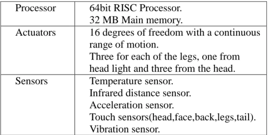
Our main experiment platform is AIBO ERS-220A made by SONY. The basic hardware specification of AIBO is shown in Table 1. By using OPEN-R SDK, we may record the data from three-axial acceleration sensors in AIBO [1][2][4][5]. The positive direction of X, Y and Z axis in the acceleration sensor are mapped to right, front and up of the robot respectively. According to the result of measurement, each axis has different unit length [11]. The unit length of X axis is 0.086784, Y axis is 0.169080 and Z axis is 0.172046 meter. The sampling rate of a frame is 125Hz, and AIBO takes 140 frames (1.12 seconds) to complete one gait cycle. Besides, in order to get more information about the status of AIBO, we also recorded the data from touch sensor under each foot. With the help of touch sensor’s feedback, we can analyze and determine the order of steps of AIBO’s walking pattern.
Table 1. The hardware specification of AIBO
Processor 64bit RISC Processor.
32 MB Main memory.
Actuators 16 degrees of freedom with a continuous range of motion.
Three for each of the legs, one from head light and three from the head.
Sensors Temperature sensor.
Infrared distance sensor.
Acceleration sensor.
Touch sensors(head,face,back,legs,tail).
Vibration sensor.
A Gait Based Approach to Detect Directional Bias of Four-Legged Robots' Direct Walking Utilizing Acceleration Sensors 6
100,000 CMOS image sensor
1.2 Related Works
H. Liu and G. Pang had proposed that the position of the robot can be detected by using acceleration sensors [7]. So if the position is known, then the direction bias is easy to be computed. D. Vail and M. Veloso have used acceleration data from AIBO to identify the surface under the robot as it walks[3]. In addition, they also used the acceleration data to predict gait velocity by using a k-nearest neighbor approach. In order to find out the directional bias, walking distance is a good starting point. Seong Yun Cho et al [10] described how to use low-cost acceleration sensors to measure the system of walking distance. Some previous research showed that the acceleration sensors were very shaky, so it is too hard to calculate the speed or traveled distance of the dog [12]. Fortunately, it is practicable to determent the relation between actual walking and acceleration by analyzing and observing the walking robot, because acceleration has some particular characteristics which would be affected by walking condition.
2 The Algorithm to Detect Directional Bias
As has been noted above, the integrated data are different from the real distance.
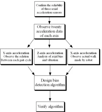
Maybe the original data is the critical issue. Consider the characteristic of each acceleration sensor data, a series of study was designed to check the validity of the data. So, the flowchart of the main research method appears in Fig.1. For the first step, we want to confirm the reliability of three-axial acceleration sensors by using Matlab software package, so a simple test was designed. Then we analyze each axis acceleration data and find out the relation between them. Finally we summarize the result and propose our method to detect directional bias.
A Gait Based Approach to Detect Directional Bias of Four-Legged Robots' Direct Walking Utilizing Acceleration Sensors 7
Fig. 1. Flowchart of research method
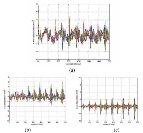
The first experiment is to let AIBO walks 5 gait cycles on the top of pasteboard for 20 times. We recorded the acceleration data of each axis and drew the data on one graph, as Fig.2 has shown. In Fig.2(a), we find that the X-axis acceleration data is unstable, but each gait cycle has similar feature. For example, there are fixed10 pulses during 5 gait cycles, and they almost happen in the same time. So we believe that the three-axial acceleration sensor has specific repeatability. Especially in first gait cycle, because the vibrations are so few that the data are very similar. But after second gait cycle the vibrations are increasing, so each data are getting different. Since the three-axial acceleration sensor on AIBO has general reliability, then we will analyze each axis data respectively.
A Gait Based Approach to Detect Directional Bias of Four-Legged Robots' Direct Walking Utilizing Acceleration Sensors 8
(a)
(b) (c)
Fig. 2. Each axis acceleration data during 5 gait cycles measured 20 times: (a) X-axis (b) Y-axis (c) Z-axis
2.1 The Characteristics of Acceleration Sensor
After confirmed the reliability of three-axial acceleration sensor on AIBO, we started to analyze each axis. For the first step, we analyze Y-axis acceleration data by integrating the acceleration twice directly. As mentioned above, the integrated data are far from the real distance measured manually. So we consider that there must be some kinds of factors that affect the Y-axis acceleration data. So far we can not compute the distance directly by using acceleration data, but the real distance has particular relation with the acceleration data. As the result of observation, we think that the vibration and the axial bias may be the main factors that cause the difference between integrated data and the real distance. It seems that the factors appear when AIBO change its own gait. It is because AIBO is on unstable state when it change gait. For example, the vibration occurs in the moment that the left front leg is raising up and the left back leg is putting down. The vibration causes the axial bias and a
A Gait Based Approach to Detect Directional Bias of Four-Legged Robots' Direct Walking Utilizing Acceleration Sensors 9
pulse. In order to find when the vibration occurs, we start to analyze Z-axis acceleration data.
In the second step, we analyze Z-axis acceleration data by comparing with the data from the touch sensor on bottom of each leg. If the
reading of the touch sensor is 0, it means that the AIBO is during swing phase. If the reading is 1, it means that the AIBO is during stance phase.
The reading from touch sensor is 0 or 1, but in order to compare the touch sensor data with acceleration data we add a fixed value on each reading of touch sensor. As Fig.3has shown, “○”means the reading from right front touch sensor; “+”means the reading from left front touch sensor; “”means the reading from right back touch sensor;
“”means the reading from left back touch sensor. In addition, we find that the time points when the pulses occur during 5 gait cycle are steady. It begins from 0.2 second (25 frame), and there is a pulse every 0.56 second (70 frame). Comparing with each leg phase, the start time point 1 in Fig.3 of these pulses is the time when right front leg is raising up and the right back leg is putting down. The time point 2 is the time when left front leg is raising up and the left back leg is putting down. So the pulse is caused by the changes between two legs on the same side. This kind of vibrations would affect each axial data
extremely. So the data seem to be unreliable during the unstable period and can not be integrated directly.
A Gait Based Approach to Detect Directional Bias of Four-Legged Robots' Direct Walking Utilizing Acceleration Sensors 10 Fig. 3. Z-axis acceleration data during 5 gait cycles compare with each leg phases
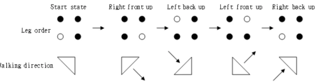
Besides, from Fig.3 we can figure out that AIBO starts its gait in the order of right front, left back, left front and right back. This gait [8][9]
is shown in Fig.4 and is the same with the notion that Hirose and Kunieda proposed [6]. Via observing walking AIBO, we find that its walking direction is straight when it raising right front leg. When it is putting right front leg down and raising left back leg up, it gets the most right position during a single gait. Then it raises left front leg and its walking direction is left forward. Eventually when it is putting left front leg down and raising right back leg up, it gets the most left position during a single gait.
Fig. 4. Start gait order of the robot with direction
In the third part, we want to know at what frame the vibrations start.
We start to analyze X-axis acceleration comparing with the trajectory of AIBO. As Fig.5 shown, the gap between dotted lines is the distance during one single gait cycle. The arrows point out the most right positions or the most left positions. We assume the velocity is 0 when AIBO reach the most right positions or the most left positions. It is because that the instant velocity should be 0 at the point when the robot changes its direction. So we can integrate data from the next arrow partially.
2.2 Bias Detection Algorithm
As has been discussed, it seems reasonable to believe the acceleration sensors on AIBO are useful in some degree of accuracy. But we find that AIBO vibrate largely at some fixed time point, so it is important to take out the acceleration data while left leg or right leg in the swing phase individually. As Fig.6 has shown, by observing the phase of each leg we decided to collect data from 23th frame to 63th frame which represented the acceleration data that the right front leg in the swing phases. In
A Gait Based Approach to Detect Directional Bias of Four-Legged Robots' Direct Walking Utilizing Acceleration Sensors 11
addition, we collect data from 97th frame to 137th which represented the acceleration data that the left front leg in the swing phases. By integrating this two data twice individually and then summing these two values up, we get a value that we called it as partial integrating value (PIV). If the PIV is positive, the center position of AIBO is going to right position. If the PIV is negative, the center position of AIBO is going to leftposition.So,thismethod isour“single gaited bias detection algorithm”.
3 Experiment Results
To test the “singlegaited biasdetection algorithm”,wegathered asinglecycleofeach sensor reading while AIBO walk on the pasteboard and record the center position of AIBO, and repeated this experiment for 30 times. We list the first 10 records to explain the result of our experiment, as shown in Table 2. The X1 field is the X-axial position of left front leg, X2 is the X-axial position of left back leg, Xc is the center position of AIBO, or the average of X1 and X2, DIV is the value directly integrated twicefrom acceleration,and θ isthebiasangle which iscomputed by X1 subtracting X2 and then divided by the distance (23cm) between front leg and back leg. If the value in Table.2 is positive, it means that the directional bias is right; otherwise, if the value in Table.2 is negative, it means that the directional bias is left.
Comparing Xc with DIV, they are different from each other from exp1 to exp10. The values of DIV are not only too large but also
upside-down in positive-negative sign. So the directional bias can not be simply computed by integrating X-axial acceleration. Comparing Xc with PIV, there are only two data (exp2 and exp7) in wrong judgment.
IfthevalueofXcequalto 0,θ would help to explain thedirectional bias.Takeexp3 forexample,thevalueofθ isnegative,so the directional bias is left, and the method determine correctly. The other data show that the proposed method can determine the directional bias.
Thecorrectrateof“singlegaited biasdetection algorithm”is93.33%, because 28/30 data are correct.
Table 2. Experiment results (in unit of cm)
NO. X1 X2 Xc DIV PIV θ
exp1 -1.3 0.7 -0.3 7.542884 -1.9959 -4.96974 exp2 -0.4 0.6 0.1 15.72617 -0.84257 -2.48955 exp3 -0.5 0.5 0 14.12934 -0.49655 -2.48955 exp4 -0.8 0.6 -0.1 13.84468 -0.64595 -3.48327 exp5 -1.2 0.6 -0.3 15.4393 -0.72316 -4.4749 exp6 -0.5 0.4 -0.05 8.680384 -0.54403 -2.24087 exp7 -0.6 0.8 0.1 8.871726 -1.71764 -3.48327
A Gait Based Approach to Detect Directional Bias of Four-Legged Robots' Direct Walking Utilizing Acceleration Sensors 12
exp8 -0.5 0.4 -0.05 6.40316 -0.49071 -2.24087 exp9 -0.3 0.2 -0.05 17.49574 -0.83063 -1.24536 exp10 -1.2 0.6 -0.3 9.290792 -1.34884 -4.4749
4 Conclusion
We have proposed an effective approach to detect the directional bias of walking four-legged robots by using acceleration data. It is because that sensor on AIBO has poor precision, so during the process of acceleration analysis we must compare the actual walking gait with acceleration data. We adjust our algorithm by the try-and-error method continuously, and with lots of attempts the relation between them had been found out. Besides, the maximum bias relative to center position of AIBO in one gait cycle is ±0.6cm, but the factor error is up to ±5.443cm so that we can not precisely get the actual bias. Although there are many possible factors to the directional bias, such as material and gradient of ground, lack of calibration, hardware malfunction, etc…, but the proposed algorithm is considered effective to all kinds of situation as long as the accelerometers function correctly.
Acknowledgements. This work is supported by the National Science Council of the Republic of China, under the grant NSC 95-2221-E-011-127.
References
1. Anton Wijbenga,Martvan deSanden ,“How To MakeAIBO Do Tricks”,University of Groningen,Netherlands,2004.
2. Bernhard Hengst,Darren Ibbotson,Son Bao Pham,Claude Sammut “The UNSW United 2000 Sony Legged Robot Software System ” , University of New South Wales , Australia,2000
3. DouglasVail,ManuelaVeloso,“Learning from AccelerometerDataon aLegged Robot”, Computer Science Department,Carnegie Mellon University,2004.
4. Franois Serra, Jean-ChristopheBaillie,“Aibo programming Using OPEN-R SDK. Tutorial", ENSTA, France ,2003.
5. Francisco Martín Rico, Rafaela González-Careaga, Jose María Canas Plaza,Vicente Matellán Olivera,“Programming Model Based on Concurrent Objects for the AIBO Robot”, Universidad Rey Juan Carlos, 2004.
6. GeorgeA.Bekey,“AutonomousRobotsFrom BiologicalInspiration fo Implementation and Control”,TheMIT Press,Cambridge,Massachusetts,London,England,2005.
7. H.Liu,G.Pang,“AccelerometerforMobileRobotPositioning,”Proc.Ofthe1999 IEEE Industry Applications Society Conference, Oct 3~7, 1999.
8. J.P.Schmiedeler,K.J.Waldron,“TheMechanicsofQuadrupedalGalloping and theFuture ofLegged Vehicles”,TheInternationalJournalofRoboticsResearch,Dec1999,,Vol.18, No.12 pp.1224-1234
A Gait Based Approach to Detect Directional Bias of Four-Legged Robots' Direct Walking Utilizing Acceleration Sensors 13
9. Makoto Toyomasu ,AyumiShinohara,“DEVELOPING DYNAMIC GAITS FOR FOUR LEGGED ROBOTS”,TheInternationalSymposium on Information Scienceand Electrical Engineering 2003, 2003, pp. 577-580
10.Seong Yun Cho, Chan Gook Park and Gyu In Jee,“Measurement System of Walking Distance Using Low-cost Accelerometers”,The 4th Asian Control Conference,Singapore,Sep 2002,pp.1799-1803.
11.Sony Corporation,“OPEN-R SDK”,2004.
12.Sven Westermark,“Programming toolsforAIBO”,2005.