Development and characterization of an all-solid-state potentiometric
biosensor array microfluidic device for multiple ion analysis
Wei-Yin Liao,
aChen-Hsun Weng,
bGwo-Bin Lee
band Tse-Chuan Chou*
a Received 6th March 2006, Accepted 6th July 2006First published as an Advance Article on the web 14th August 2006 DOI: 10.1039/b603364d
A microfluidic device with an all-solid-state potentiometric biosensor array was developed using microfabrication technology. The sensor array included a pH indicator, and potassium and calcium ion-selective microelectrodes. The pH indicator was an iridium oxide thin film modified platinum microelectrode and the iridium oxide was deposited by an electrochemical method. The potassium and calcium ion-selective microelectrodes were platinum coated with silicon rubber based ion-selective membranes with respectively potassium (valinomycin) and calcium (ETH 1001) ionophores. The detection system was integrated with a micro-pneumatic pump which can continuously drive fluids into the microchannel through sensors at flow rates ranging from 52.4 ml min21to 7.67 ml min21. The sensor array microfluidic device showed near-Nernstian responses with slopes of 62.62 mV ¡ 2.5 mV pH21,
53.76 mV ¡ 3 mV 2log[K+]21and 25.77 mV ¡ 2 mV 2log[Ca2+]21at 25uC ¡ 5 uC, and a linear response within the pH range of 2–10, with potassium and calcium concentrations between 0.1 M and 1026M. In this study the device provided a convenient way to measure the concentration of hydrogen, potassium and calcium ions, which are important
physiological parameters
Introduction
The rapid and accurate detection of electrolyte concentrations in biological fluids, e.g. blood or urine, is indispensable for diagnosing various health problems and the treatment of diseases.1–3 Usually, the biological samples may need to be sent to a central laboratory for analysis and the results of routine tests would take several hours, sometimes days. Therefore, the development of a practical tool which is operated easily, requires low sample volumes and gives rapid analytical results would be of considerable use. In recent years many research groups have focused on developing multi-function sensing devices for biological and chemical analysis,4–8point-of-care testing,9clinical and forensic analy-sis,10,11molecular diagnosis and drug discovery12–14by using
microfabrication technology.
Among all kinds of devices, a microfluidic device which can monitor physiological parameters was highlighted as having great potential. It is a bio-instrument that combines micro-fabrication, microfluidics, microelectrodes and micromecha-nics to create self-contained bio-micro-electro-mechanical systems (BioMEMS),15,16which serve as a complete biological laboratory-on-a-chip. Sensors located in the microchannels can avoid damage from excess force, need only small volumes of samples and are convenient to carry.17,18The sensing of pH,
potassium and calcium ion concentrations has been used to detect perturbations in metabolic activity as a result of receptor activation, toxin effects and drug influence, or enzyme
inhibition. Biosensors based on the extracellular measurement of ion concentrations have been demonstrated by using electrochemical type sensors. Therefore, a microfluidic device with the integration of sensing electrodes can provide a fast, low-sample-consumption, highly sensitive and reliable method to assess these important physiological parameters.
In this study, a microfluidic device integrated with a liquid handling environment and a detection sensor array for multiple ion analysis was created. Microfabrication technology was adopted to create the multiple ion analysis microfluidic device, which included micropumps, microchannels and microelectrodes. SU-8-50 negative photoresist was used to produce the microfluidic templates. Elastic polydimethyl-siloxane (PDMS) was used to duplicate microchannels with inverse microfluidic structures from the templates. A micro-pump can be made to function by using compressed air in the microchannels of two flexible PDMS layers to cause the peristaltic membrane to deflate so that the fluids can continuously flow in a specific direction. The microelectrodes for the detection of pH, potassium ion concentration and calcium ion concentration were Pt electrodes modified with iridium oxide and ion-selective membranes with potassium and calcium ionophores. The iridium oxide was chosen as the pH sensing material because it has a wide pH response range, fast response time, high pH sensitivity, low potential drift and low sensitivity to redox pair interference.19,20Ion-selective electro-des were used for sensing potassium and calcium ions because of their high selectivity and short response times.21 The performances of the pH indicator and potassium and calcium ion-selective electrodes in the microfluidic system were explored. Their electrochemical properties were also compared with electrodes in a beaker system.
a
Department of Chemical Engineering, National Cheng Kung University, Tainan 701, Taiwan
b
Department of Engineering Science, National Cheng Kung University, Tainan 701, Taiwan
Experimental
Materials and reagentsPoly(dimethylsiloxane) (Sil-More Industrial Ltd, Sylgard 184A and Sylgard 184B, USA), photoresist (AZ-400K, Clariant K.K, Technical & Production Dept, Japan) and thick photoresist (SU-8-50, MicroChen, Newton, MA, USA) were the main component materials for fabrication of the micro-fluidic devices.
Hydrogen peroxide (30% solution in water), iridium tetrachloride, oxalic acid dihydrate, and anhydrous potassium carbonate for the preparation of iridium oxide deposition solutions were purchased from Aldrich, Inc.
The compositions of ion-selective polymer membranes in this study are as follows, the lipophilic additive potassium tetrakis(4-chlorophenyl)borate (0.6 wt%), ionophores (1 wt%), silicon rubber (33 wt%) and (2-ethylexyl) adipate (65.4 wt%). In this study, the ionophores for sensing potassium and calcium ions were valinomycin and 3,6-dioxaoctanediamide (ETH 1001), respectively.The one-component room tempera-ture vulcanizing-type silicon rubber 3104 (3140-RTV sealant) was purchased from Dow corning (Midland, MI, USA). The lipophilic additive used was potassium tetrakis(4-chlorophe-ny)borate (KClTPB). The lipophilic additives and the iono-phores were both obtained from Fluka Inc. The chemical components of the ion-selective membrane were dissolved into tertrahydrofuran (THF) to form a cocktail solution for easy coating onto the microelectrodes.
Device description
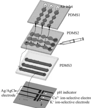
Fig. 1 shows a schematic layout of the multiple ion analysis microfluidic device. The microfluidic device was constructed
by uniting three essential components, namely, the micro-pump, microchannels and potentiometric sensor array. The device in this study was composed of modular components sandwiched as several layers, i.e., top layer with the micro-pump, middle layer with the microchannels for the fluid, and the bottom layer with sensing microelectrodes on a glass substrate (Fig. 1). For the top layer of the device, two-layer PDMS structures (PDMS1 and PDMS2) form closed air channels such that pneumatic micropumps can be driven by using compressed air. Note that the three holes on the PDMS1 surface were used for input of compressed air. The micro-channels for the introduction of the analyte solution into the device were formed by bonding the PDMS2, PDMS3 and the glass substrate (Fig. 1). The PDMS2 and PDMS3 layers have three holes to connect with each other. The direction of the flowing analyte solution is shown by dotted lines in Fig. 1. The bottom part of the device is the detection system. It has three pairs of solid-state potentiometric sensors, which are a pH indicator vs. Ag/AgCl, a calcium ion-selective electrode vs. Ag/AgCl and a potassium ion-selective electrode vs. Ag/AgCl, on the glass substrate, as shown in the bottom part of Fig. 1. These three sensors were platinum electrodes modified with iridium oxide and ion-selective membranes containing calcium and potassium ionophores. The dimensions of the chip are 2.5 cm 6 2.8 cm.
Fabrication process
Detailed information on the fabrication process for the micropump, microchannels and potentiometric sensors array are given in the following sections.
Fabrication of microfluidic devices
The microfluidic device was fabricated by using PDMS casting methods to produce inverse structures of microfluidic devices from a SU-8 thick-photoresist mold on a silicon substrate. Three diverse SU-8 mold masters were first formed, one for the air control channels (for casting the PDMS1 of Fig. 1), one for the top part of microfluidic channels (for casting the PDMS2) and one for the bottom part of the microfluidic channels (for casting the PDMS3). These three mold masters with different microstructures were manufactured by using a photolithogra-phy process of patterning a thick photoresist on a silicon wafer. PDMS was spun onto its corresponding molds at 800 rpm for 30 s and then cured at 95uC for 120 min. After the curing process, the PDMS layers were mechanically peeled off from their molds to give PDMS1, PDMS2 and PDMS3. The three PDMS layers were bonded together using an oxygen plasma treatment. Finally, the PDMS layers structures and the glass substrate containing sensing electrodes were aligned and bonded.
Fabrication of microelectrodes
Microelectrodes were fabricated by using a standard photo-lithography process and thin-film deposition/patterning tech-niques. The working electrodes were fabricated by depositing and patterning a Pt (1000 A˚ ) layer with an adhesion layer of Cr (300 A˚ ) on a glass substrate using an E-beam evaporation
Fig. 1 A three-dimensional schematic representation of the multiple ions analysis microfluidic device.
process, followed by a standard lift-off process. One of the Pt electrodes was selectively modified with iridium oxide by an electrodeposition method through a small window (2.0 mm 6 3.0 mm) in the photoresist insulation layer. The deposition process was performed in a three-electrode cell system, in which the working electrode was a Pt microelectrode, the counter electrode was a Pt foil with a surface area equal to 1 cm2and the reference electrode was a commercial reference electrode (Ag/AgCl in saturated KCl solution). Light-blue iridium oxide film was created on the platinum electrode using the cyclic voltammery method between 0.0 V and 0.6 V vs. a commercial reference electrode at 20 mV s21for 300 cycles. The deposition solutions were made according to the work reported by Marzouk1 et al., and the procedure was as follows. IrCl4?xH2O (75 mg) was dissolved in 50 ml water and stirred
for 30 min. Hydrogen peroxide (0.5 ml) was added and the mixture stirred for 10 min. Then, dehydrated oxalic acid (250 mg) was added and the mixture stirred for 10 min. Finally, the solutions were adjusted to pH = 10.5 by adding anhydrous potassium carbonate, and left at room temperature for 2 days to stabilize.
The other two Pt electrodes were modified with ion-selective membranes for sensing the calcium and potassium ions of the test solutions. Ion-selective electrodes were fabricated by selectively casting the ion-selective membrane cocktail solu-tions onto the Pt electrodes through a plastic Teflon mask with two open windows for each with an area equal to 2.0 mm 6 3.0 mm. After coating, the ion-selective microelectrodes were dried in air at room temperature for 3 days.
The reference electrodes (2.0 mm 6 4.0 mm) were fabricated by depositing and patterning Ag (1000 A˚ )/Au (300 A˚)/Cr (300 A˚ ) layers. Note that Au/Cr layers were used to promote adhesion. The electrodes were formed using similar photo-lithography and E-beam evaporation processes as described above. Finally, AgCl was selectively formed by dropping 0.1 M FeCl3 solution onto an Ag/Au/Cr microelectrode
surface to generate an oxidation–reduction reaction on the Ag through a small window in the photoresist insulation layer electrodes.
Measurement procedure
Flow injection potentiometry measurements were performed by continuously pumping analyte solution into the three different flow channels containing the various sensing micro-electrodes. Potentiometric measurements were used to estimate the potential shifts and were performed with a two-electrode system in which the working electrodes were iridium oxide modified and ion-selective membrane coated platinum micro-electrodes, while the reference electrode was a pseudo Ag/AgCl reference electrode. The potential signal outputs were mea-sured as a function of pH from 2 to 10, and potassium and calcium ions concentrations from 0.1 M to 1026 M in the testing solutions. The buffer and primary ion solutions for evaluation of the pH indicator and ion-selective electrodes were 0.1 M KNO3–0.01 M H3PO4–H3BO3–CH3COOH22
and different nitric salt solutions. Furthermore, the FIM (fixed interference ion method) was used to evaluate the ion-selective coefficients of the ion-selective electrodes. The
fixed concentrations of interfering ions used were as follows: [Li+] = 1.15 6 1023M, [Na+] = 0.15 M, [K+] = 4.5 6 1023, [NH4+] = 4.5 6 1023M, [Ca2+] = 2.5 6 1023M and [Mg2+] =
1 6 1023. All solutions prepared in this study were made using
deionized water (Millipore Water System) with a resistance ¢18.3 MV. All measurements in this study were recorded and displayed by a potentiostat (CHI Instruments, model 614a).
Results and discussion
Performance of the micropump
Fig. 2(A) shows a schematic representation of the peristaltic activation of PDMS membranes driven by external com-pressed air through tubing. Three electromagnetic valve (EMV, SMC Inc., S070M-5BG-32, Japan) switches were used to individually control the movement of each PDMS membrane, which was driven by a control circuit. The control system is composed of a control circuit, EMV switches, and an air compressor (JUN-AIR Inc., MDR2-1A/11, Japan). An 8051 microcontroller (AT89C51, ATMEL, USA) was used to provide signals to control the EMV switches such that the compressed air can be injected into the air channels to activate the micropumps. The pumping rate of the micropumps is regulated by adjusting the operating frequency of the EMVs and the applied pressure of the compressed air. The valving effect can be also achieved by providing compressed air to
Fig. 2 (A) Schematic representation of the peristaltic activation of three sets of thin films to pump the fluids to flow in a specific direction. (B) Relationship between pumping rate and driving frequency for the peristaltic pneumatic micropump. The maximum pumping rate is 52.4 ml min21at a frequency of 36 Hz with a pressure of 10 psi.
completely shut off the flow channel. The pumping rates obtained from the pneumatic micropumps at different frequencies are shown in Fig. 2(B). The pumping rates can be controlled by changing the driving frequency and the applied pressure. In order not to break the PDMS membrane, only a pressure of 10 psi was used for testing. The micropump can continuously drive fluids into the microchannel. The maximum pumping rate obtained is 52.4 ml min21at a pressure
of 10 psi and a driving frequency of 36 Hz.
Response of potentiometric sensors array in the flow injection mode
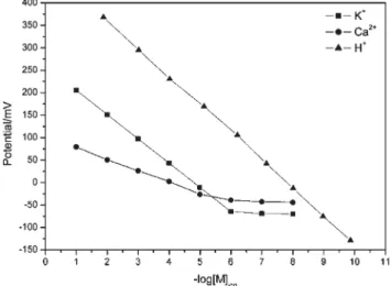
Fig. 3 presents the calibration curves for the pH indicator and calcium and potassium ion-selective electrodes determined individually in the flow injection mode at a flow rate of 35 ml min21. Each data point shown in Fig. 3 is the average value of the open circuit potential of the sensing electrodes after injecting the desired pH of 0.1 M KNO3–0.01 M H3PO4–
H3BO3–CH3COOH and the necessary concentrations of
KNO3and Ca(NO3)2solutions into the device for 5 minutes.
The pH indicator and calcium and potassium ion-selective electrodes exhibited near-Nernstian responses within the pH region from pH = 1.89 to 8.99 and calcium and potassium concentration ranges from 0.1 M to 1026 M. The detection limits observed for calcium and potassium ion-selective electrodes in this microfluidic device were 2.14 6 1026 M and 3.42 6 1026 M, respectively. The Pt modified iridium oxide electrode pH indicator, exhibited a near-Nernstian response of 62.04 mV change per pH unit, over a pH range between 2.00 to 10.00, while the calcium and potassium ion-selective electrodes presented electrode responses of 53.98 mV and 25.06 mV change per concentration decade and a log-linear range between 0.1 M and 1026M.
Furthermore, the sensitivities and the open circuit potentials of the pH indicator, calcium and potassium ion-selective electrodes in the microfluidic device were compared with the in-beaker system using different types of silver/silver chloride reference electrodes. In other words, the sensitivity and the open circuit potential of the sensing electrode in different systems was assessed, and the results are shown in Table 1. First of all, it can be observed that the sensitivities of the pH indicator and calcium and potassium ion-selective electrodes were similar regardless of which system they were being used in. In addition, the open circuit potentials of the sensing electrodes with an Ag/AgCl reference electrode in the microfluidic device have a great resemblance to the in-beaker system using the same type reference electrode. However, open circuit potentials of each sensing electrodes in these two systems would become obviously different when using Ag/AgCl in saturated KCl solution as reference electrodes. However, changing the standard electrode will not affect the performances of the sensing electrodes.
The selectivity coefficients for calcium and potassium ion-selective electrodes in the beaker system and in the microfluidic device at 35 ml min21are presented in Table 2. In the beaker system using Ag/AgCl in saturated KCl solution reference electrode, the calcium and potassium ion-selective electrodes exhibit excellent selectivity against common interfering ions. When the reference electrode was substitute by Ag/AgCl in the beaker system, the selective properties of these two ion-selective electrodes were still as good as when using Ag/AgCl in saturated KCl solution as the reference electrode. Eventually, ion-selective electrodes and Ag/AgCl reference electrodes were created on the glass substrates and integrated with the microfluidic system. Their selectivity coefficients revealed good selectivity against common interfering ions in the microfluidic device.
From these results, it is clear that the sensors which have been successfully created in the beaker system can be integrated into the microfluidic system by using microfabrica-tion technology without influencing their performances.
Fig. 3 Calibration plots determined individually for pH indicator, calcium and potassium ion-selective electrodes in the microfluidic device operated in flow injection potentiometry mode at 35 ml min21.
The calibration solution, made as 0.1 M KNO3–0.01 M H3PO4–
H3BO3–CH3COOH and adjusted to the desired pH with 1 M KOH or
1 M HNO3 as required, was injected into the device. KNO3 and
Ca(NO3)2stock solutions were diluted as necessary to give a series of
calibration solutions ranging from 1021M to 1028M.
Table 1 Sensitivities of pH indicator and calcium and potassium ion-selective electrodes in a beaker system and in the microfluidic device at 35 ml min21
Sensitivitya/2mV
(log[M]ion)
21 Open circuit
potentiala,b/mV In-beaker system using Ag/AgCl with inner-filling saturated KCl solution as reference electrode
pH indicator 63.54 478.3 K+ISE 57.13 285.6 Ca2+ISE 27.32 230
In-beaker system using Ag/AgCl as reference electrode pH indicator 62.50 252
K+ISE 55.80 48
Ca2+ISE 25.88 9.8
In the microfluidic device using Ag/AgCl as reference electrode pH indicator 62.04 230.2
K+ISE 53.98 43.34
Ca2+ISE 25.06 2.5 a
Note that the sensitivity and open circuit potential of each kind of electrode was the average value of three times tests.bOpen circuit
potential for pH indicator was measured at pH = 4.03, and for potassium and calcium ion-selective electrodes was measured at 1024M potassium nitrate and calcium nitrate, respectively.
Table 2 Selectivity coefficients determined for calcium and potassium ion-selective electrodes in beaker system and in the microfluidic device at 35 ml min21
log KPot ði;jÞ
a
In-beaker system using Ag/AgCl with inner-filling saturated KCl solution as reference electrode j = K+ j = Na+ j = NH
4+ j = Li+ j = Ca2+ j = Mg2+
K+ISE — 22.89 22 22.32 23.01 23.25
Ca2+ISE 25.14 25.01 23.32 22.81 — 22.63
In-beaker system using Ag/AgCl as reference electrode
K+ISE — 22.75 21.89 22.29 22.98 23.20
Ca2+ISE 25.01 24.98 23.30 22.76 — 22.59
In the microfluidic device using Ag/AgCl as reference electrode
K+ISE — 22.76 21.99 22.27 22.87 23.21
Ca2+ISE 24.98 24.97 23.31 22.79 — 22.58
ai = the primary ions, j = the interfering ions
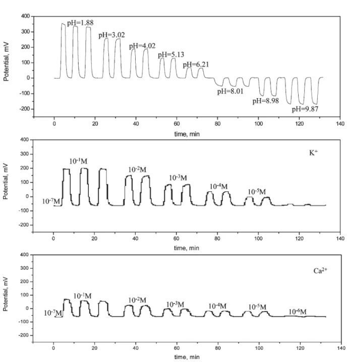
Fig. 4 Typical simultaneous response curves of pH indicator, calcium and potassium ion-selective electrodes in the microfluidic device at 35 ml min21.
Simultaneous responses of the sensors array
The device has three individual micropumps and micro-channels for each sensing electrode of the sensor array. One pair of micropump and flow channel was used for detection of pH, another for potassium ion concentrations of the analyte solutions and the other for calcium ion concentrations of the test solutions as shown in Fig. 1. In other words, this device can detect the pH, potassium and calcium ion concentrations of the test solution simultaneously by starting these three micropumps. The simultaneous response curves of the pH indicator, calcium and potassium ion-selective electrodes in the microfluidic device at a flow rate equal to 35 ml min21are presented in Fig. 4. The background solutions for pH, potassium ion concentration and calcium ion concentration detections were 0.1 M KNO3–0.01 M H3PO4–H3BO3–
CH3COOH solution at pH = 7.15, 1027 M KNO3 solution
and 1027M Ca(NO3)2solution, respectively. Each
concentra-tion change pulse for the sensing electrodes was repeated for two or three times to evaluate the reproducibility. From the results, the open circuit potentials of the sensing electrodes for each concentration change pulse could reach a similar value with ¡3 mV deviation. In Fig. 4, the pH indicator exhibited an electrode response of 62.16 mV change per pH and a log-linear range between pH = 2.00 to pH = 10.00. The calcium and potassium ion-selective electrodes showed responses of 53.87 mV and 25.17 mV changes per concentration decade, respectively, and a log-linear range between 0.1 M and 1026M. From Fig. 4, it is apparent that the microfluidic device can continuously detect the pH, potassium ion and calcium ion concentrations simultaneously with the performance of each sensing electrode as good as in individual measurements.
In addition, the flow rate effect on the electrodes was also investigated and the results are shown in Fig. 5. The range of the flow rate examined was between 52.4 ml min21 and 10 ml min21. From Fig. 5, the pH indicator exhibited a
sensitivity equal to 62.62 mV ¡ 2.5 mV at this flow rate region and a log-linear range between pH = 2.00 to pH = 10.00. The calcium and potassium ion-selective electrodes showed a sensitivity equal to 53.76 mV ¡ 3 mV and 25.77 mV ¡ 2 mV, respectively, and a log-linear range between 0.1 M and
1026 M. From the results, the sensitivities of the sensing
electrodes appear not to be influenced seriously when the device is operated at a flow rate ranging from 52.4 ml min21to
10 ml min21.
The response times observed for the attaining of 90% response of each pulse peak with the flow injection model are listed in Table 3. Interestingly, the response times of each sensing electrode in the microfluidic device were different when they were in the beaker system. From the literature,23,24the response time of the sensors will be a result of the controlling factors related to convection, the diffusion of the ion to be measured through the stagnant layer (boundary layer), the diffusion within the ion-selective membrane and the establish-ment of a liquid-junction potential at the reference electrode. In this study, sensors revealed near-Nernstian response, ion concentration changes in the membrane were negligible, and thus diffusion within the membrane is not relevant. Therefore, ion diffusion through a stagnant aqueous layer plays an important role in the response time. From Table 3, in the beaker system using a stirrer, the response times of the sensors were short and independent of which type of reference electrode was used. In other words, the detected ions migrate to the sensors surface by diffusion and convection through a
Fig. 5 Sensitivities of pH indicator, calcium and potassium ion-selective electrodes at different flow rates in the microfluidic device.
Table 3 Response times of pH indicator and calcium and potassium ion-selective electrodes in the microfluidic device (A) and in beaker system (B) (A) Background solution/ 2log[M]ion Pulse injection concentration/ 2log[M]ion Response time in a 35 ml min21microfluidic
device using Ag/AgCl as reference electrode/s pH 2pK+ 2pCa2+ pH 2pK+ 2pCa2+ 7.15 1.88 49 7.15 3.02 69 7.15 4.02 68 7.15 5.13 70 7.15 6.21 74 7.15 8.01 103 7.15 8.98 123 7.15 9.89 130 7 1 52 7 2 70 7 3 74 7 4 71 7 5 75 7 6 78 7 1 55 7 2 73 7 3 75 7 4 72 7 5 76 7 6 79 (B)
Response time in beaker systema/s
Using commercial Ag/AgCl with inner-filling saturated KCl solution as reference electrode
Using Ag/AgCl as reference electrode pH indicator 11 14
K+ISE 7 15
Ca2+ISE 7.6 18
stagnant aqueous layer in a short time because it is a very thin layer in the beaker system with a stirrer. However, the bound-ary layer will increase dramatically in the microfluidic system and the ion distribution in the microchannel depends mostly on diffusion (the solutions were not stirred in the microfluidic device). In this situation, the response time of sensors in the microfluidic system will increase. In addition, the response times of the sensors increased when the concentration of ions to be detected in the injection solution decreased. This was caused by the decrease in the ion concentration of the injection solution reducing the driving force of the diffusion. Thus, ions need more time to migrate to the sensors surface, and thus the response time will become more protracted. This can be observed in the lower response times seen in basic solution compared to acidic solutions (Table 3). From a practical viewpoint, the response times of the device are acceptable for self-examination of a patient at home.
Conclusions
We created an all-solid-state potentiometric sensor array which included a pH indicator together with potassium and calcium ion-selective electrodes on a transparent glass slide using selective electrochemical deposition of iridium oxide and spin-coating ion-selective membranes onto the lithographically defined Pt thin-film electrodes. The sensor array was integrated with a micropump and microchannels to form an auto-sampling microfluidic device. The characteristics of this array in a microfluidic device were highly reproducible and showed sensitivities of 62.62 mV ¡ 2.5 mV pH21, 53.76 mV ¡ 3 mV 2log[K+]21and 25.77 mV ¡ 2 mV 2log[Ca2+]21. From
the results, the developed multiple ion analysis microfluidic device successfully measured the solution pH in the region between pH = 2.00 to pH = 10.00, and potassium and calcium ions concentration from 0.1 M to 1026 M. In comparison with large-scale instruments, this device is smaller, consumes a smaller sample volume, can be mass produced and is easily carried.
Acknowledgements
The support of the Ministry of Education of the Republic of China (Grant No. EX-91-E-FA09-5-4) and National Cheng
Kung University are gratefully acknowledged. Also, the access provided to major fabrication equipment at the Center for Micro/Nano Technology Research, National Cheng Kung University is greatly appreciated.
References
1 M. A. Schwarz and P. C. Hauser, Lab Chip, 2001, 1, 1–6. 2 B. Timmer, W. Sparreboom, W. Olthuis, P. Bergveld and A. van
den Berg, Lab Chip, 2002, 2, 121–124.
3 X. S. Zhu, C. Gao, J. W. Choi, P. L. Bishop and C. H. Ahn, Lab Chip, 2005, 5, 212–217.
4 D. J. Beebe, G. A. Mensing and G. M. Walker, Annu. Rev. Biomed. Eng., 2002, 4, 261–286.
5 S. C. Jakeway, A. J. de Mello and E. L. Russell, Fresenius’ J. Anal. Chem., 2000, 366, 525–539.
6 T. Chovan and A. Guttman, Trends Biotechnol., 2002, 20, 116–122.
7 W. T. Liu, L. Zhu, Q. W. Qin, Q. Zhang, H. H. Feng and S. Ang, Lab Chip, 2005, 5, 1327–1330.
8 C. F. Lin, G. B. Lee, C. H. Wang, H. H. Lee, W. Y. Liao and T. C. Chou, Biosens. Bioelectron., 2006, 21, 1468–14751. 9 A. J. Tudos, G. A. J. Besselink and R. B. M. Schasfoort, Lab Chip,
2001, 1, 83–95.
10 E. Verpoorte, Electrophoresis, 2002, 23, 677–712.
11 A. Bange, H. B. Halsall and W. R. Heineman, Biosens. Bioelectron., 2005, 20, 2488–2503.
12 A. S. Rudolph and J. Reasor, Biosens. Bioelectron., 2001, 16, 429–431.
13 Y. Huang, E. L. Mather, J. L. Bell and M. Madou, Anal. Bioanal. Chem., 2002, 372, 49–65.
14 D. L. Polla, A. G. Erdman, W. P. Robbins, D. T. Markus, J. Diaz-Diaz, R. Rizq, Y. Nam, H. T. Brickner, A. Wang and P. Krulevitch, Annu. Rev. Biomed. Eng., 2000, 2, 551–576. 15 A. C. R. Grayson, R. S. Shawgo, A. M. Johnson, N. T. Flynn,
Y. W. Li, M. J. Cima and R. Langer, Proc. IEEE, 2004, 92, 6–21.
16 R. Davidsson, F. Genin, M. Bengtsson, T. Laurell and J. Emneus, Lab Chip, 2004, 4, 481–487.
17 J. S. Rossier and H. H. Girault, Lab Chip, 2001, 1, 153–157. 18 M. Kudera, Y. Nakagawa, S. Fletcher and H. A. O. Hill, Lab Chip,
2001, 1, 127–131.
19 S. A. M. Marzouk, S. Ufer, R. P. Buck, T. A. Johnson, L. A. Dunlap and W. E. Cascio, Anal. Chem., 1998, 70, 5054–5061. 20 S. A. M. Marzouk, Anal. Chem., 2003, 75, 1258–1266.
21 B. K. Oh, C. Y. Kim, H. J. Lee, K. L. Rho, G. S. Cha and H. Nam, Anal. Chem., 1996, 68, 503–508.
22 A. Fog, Sens. Actuators, 1984, 5, 137–146.
23 D. Ammann, Ion-selective Microelectrodes, Springer-Verlag, New York, 1986, p. 82.
24 E. Bakker, P. Buhlmann and E. Pretsch, Chem. Rev., 1997, 97, 3083–3132.

![Table 3 Response times of pH indicator and calcium and potassium ion-selective electrodes in the microfluidic device (A) and in beaker system (B) (A) Background solution/ 2log[M] ion Pulse injectionconcentration/2log[M]ion Response time in a35 ml min21 mic](https://thumb-ap.123doks.com/thumbv2/9libinfo/8996514.284474/6.892.462.826.138.682/indicator-potassium-selective-electrodes-microfluidic-background-injectionconcentration-response.webp)
