Magnetically tunable room-temperature 2
ππππ
liquid crystal terahertz phase shifter
Chao-Yuan Chen, Cho-Fan Hsieh+, Yea-Feng Lin+, Ru-Pin Pan+, and Ci-Ling Pan
Institute of Electro-Optical Engineering and
+Department of Electrophysics
National, Chiao Tung University, Hsinchu, Taiwan 300, R.O.C.
[email protected], [email protected]
Abstract: Tunable phase shift up to 360° at 1 THz is achieved with a liquid
crystal (LC) device. The key to this design is (1) the use of a nematic LC, E7, which exhibits a birefringence of ~ 0.17 (0.2 – 1.2 THz); (2) a LC cell (3-mm in thickness) with sandwiched structure to increase the interaction length while minimizing interface Fresnel losses; and (3) the use of magnetic field to align the thick LC cell and achieve continuous tuning of phase from 0 to 360°. This device can be operated over a broad range near room temperature.
2004 Optical Society of America
OCIS codes: (230.3720) Liquid-crystal devices, (260.3090) Infrared, far, (320.0320) Ultrafast Optics, THz.
References and links
1. D. Mittleman, “Terahertz Imaging,” in Sensing with THz radiation, (Spring-Verlag, New York, 2002). 2. Peter H. Siegel,” Terahertz technology,” IEEE Trans. Microwave Theory Tech., 50, 910-928 (2002). 3. B. Ferguson and X.-C. Zhang,” Materials for terahertz science and technology,” Nature Materials, 1, 26-33
(2002).
4. I. H. Libon, S. Baumgärtner, M. Hempel, N. E. Hecker, J. Feldmann, M. Koch, and P. Dawson, “An optically controllable terahertz filter,” Appl. Phys. Lett. 76, 2821-2823 (2000).
5. R. Kersting, G. Strasser, and K. Unterrainer,” Terahertz phase modulator,” Electron. Lett. 36, 1156-1158 (2000).
6. T. Kleine Ostmann, M. Koch, and P. Dawson,” Modulation THz radiation by semiconductor nanostructures,” Microwave Opt. Tech. Lett. 35, 343-345 (2002).
7. K. C. Lim, J. D. Margerum, and A. M. Lackner,” Liquid crystal millimeter wave electronic phase shifter,” Appl. Phys. Lett. 62, 1065-1067 (1993).
8. D. Dolfi, M. Labeyrie, P. Joffre, and J. P. Huignard,” Liquid crystal microwave phase shifter,” Electron. Lett. 29, 926-928 (1993).
9. T.-R. Tsai, C.-Y. Chen, C.-L. Pan, R.-P. Pan, and X.-C. Zhang,” Terahertz time-domain spectroscopy studies of the optical constants of the nematic liquid crystal 5CB,” Appl. Opt. 42, 2372-2376 (2003).
10. R.-P. Pan, T.-R. Tsai, C.-Y. Chen, C.-H. Wang, and C.-L. Pan,” The refractive indices of nematic liquid crystal 4’-n-pentyl-4-cyanobiphenyl in the THz frequency range,” Mol. Cryst. Liq. Cryst. (to be published in May 2004 ).
11. T.-R Tsai, C.-Y. Chen, R.-P. Pan, C.-L. Pan, and X.-C. Zhang,” Electrically controlled room temperature terahertz phase shifter with liquid crystal,” IEEE Microwave Wireless Comp. Lett. 14, 77-79 (2004). 12. C.-Y. Chen, T.-R Tsai, C.-L. Pan, R.-P. Pan,” Room temperature terahertz phase shifter based on
magnetically controlled birefringence in liquid crystals,” Appl. Phys. Lett. 83, 4497-4499 (2003). 13. P. G. de Gennes and J. Prost, The Physics of Liquid Crystals, 2nd ed. (Oxford, New York, 1983), Chap. 3. 14. D.-D. Huang, X.-J. Yu, H.-C. Huang, and H.-S. Kwok,” Design of polarizing color filters with
double-liquid-crystal cells,” Appl. Opt. 41, 4638-4644 (2002).
15. K. Komori, T. Sugaya, M. Watanabe, T. Hidaka,” Ultrafast coherent control of excitons using pulse-shaping technique,” Jan. J. Appl. Phys. 39, 2347-2352 (2000).
17. Z. Jiang, M. Li, and X. -C. Zhang,” Dielectric constant measurement of thin films by differential time-domain spectroscopy,” Appl. Phys. Lett. 76, 3221-3223 (2000).
18. P. Yeh, and C. Gu, Optics of Liquid Crystal Displays, (Wiley Interscience Publication, New York, 1999), Chap. 3.
19. R.-P. Pan, T.-R. Tsai, C.-Y. Chen, and C.-L. Pan,” Optical constants of two typical liquid crystals 5CB and PCH5 in the THz frequency range,” J. Bio. Phys. 29, 335-338 (2003).
20. Eugene Hecht, Optics, 3rd ed. (Addison Wesley Longman, New York, 1998), Chap. 4.
1. Introduction
In recent years, remarkable progress has been made in Terahertz (THz) photonics. With the development of solid-state femtosecond lasers and advanced optoelectronic THz-devices, a new era of fundamental and applied THz science is opening up. THz studies ranging from investigations of ultrafast dynamics in materials to medical, environmental sensing and imaging are actively explored [1-3]. For these and future applications in THz communication and surveillance, quasi-optic components such as phase shifters, modulators, attenuators and polarizers are indispensable. For tunable phase shifting application, several groups have demonstrated devices based on optically or electrically controlled carrier concentration in quantum well structures [4-6]. These quantum-well-based THz phase shifters, however, have not yet demonstrated 2π phase shift and need be operated at temperatures far below room temperature.
The large birefringence of liquid crystals (LCs) is well known and has been employed successfully for phase shifting of microwave and millimeter wave signals previously [7, 8]. In THz frequency range, we have recently determined the complex refractive index of a nematic LC 4’-n-pentyl-4-cyanobiphenyl (5CB) at room temperature by THz time-domain spectroscopy (THz-TDS) [9, 10]. Significantly, the 5CB exhibits relatively large birefringence and small extinction coefficient at frequencies around 1 THz. An electrically controlled room temperature THz phase shifter with 5CB has also been demonstrated by the authors [11]. A maximum phase shift of 4.07° was shown at 1.07 THz when the interaction length was 38.6 µm. The driving voltage and corresponding field were 177 V and 589 V/cm, respectively. The high voltage was required because of the large separation (>2mm) between the electrodes to avoid blocking the THz beam. The thickness of the 5CB layer required to achieve a 2π phase shift at 1 THz would be ~1.4 mm. By using magnetically controlled birefringence in a 5CB cell with nominal thickness of 1.5 mm, we were able to achieve a maximum phase shift of 141º at 1.025 THz [11]. The estimated thickness of the 5CB layer for achieving a 2π phase shift at 1 THz is about 3.18 mm, but the alignment of the LC layer becomes increasingly difficult with such thick cells. This is overcome in this work by employing a LC cell with a sandwiched structure and a different LC, E7 (Merck). Larger than 2π phase shift around 1 THz is demonstrated for the first time. We also report the complex refractive index of E7, which exhibits birefringence comparable to that of 5CB. Further, the nematic range of E7 (-10°C ~ 61°C) is significantly larger than that of 5CB (24°C ~ 35°C), making it more convenient for practical applications.
2. Basic principles and experimental setup
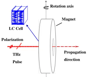
The LC THz Phase shifter consists of a homeotropically aligned LC cell and a rotary magnet as shown in Fig. 1. The rotation axis is perpendicular to both of the polarization direction and the propagation direction of the THz wave. The magnetic inclination angle, θ, is defined as the angle between the magnetic field and the propagation direction. The effective refractive index of LC changes with the LC molecular orientation [13], which is controlled by the angle θ. The phase shift, δ(θ), due to magnetically controlled birefringence is given by
∫
∆
=
L effz
dz
n
c
f
0)
,
(
2
)
(
θ
π
θ
δ
,
(1) where L is the thickness of LC layer, ∆neff is the change of effective birefringence, f is thefrequency of the THz waves and c is the speed of light in vacuum.
If the magnetic field is large enough such that the LC molecules are reoriented parallel to the magnetic field. The phase shift, δ(θ), in Eq. (1) can then be re-written as
− + = − o e o n n n c f L 2 1 2 2 2 2( ) sin ( ) cos 2 ) (
θ
π
θ
θ
δ
,
(2)where no and ne are the ordinary and extra-ordinary refractive indices of the LC. The theoretical
phase shift can be calculated if we know the no and ne of LC and the thickness of the LC layer.
Magnet THz Pulse Polarization LC Cell Rotation axis Propagation direction
Fig. 1. The schematic diagram of the LC THz phase shifter. The inset shows the sandwiched structures of the LC cells used.
When the LC layer is thicker than 1.5 mm, the orientation of LC molecules in the bulk is usually unstable and has many domains. One obvious solution is employing multiple LC cells. Previously, two LC cells were used by Kwoket al. [14] in a polarizing color filter in visible range. Another double cell design has been used in a pulse shaper for ultrafast coherent control of excitons by Hidaka et al. [15]. A LC cell with a sandwiched structure (see the inset of Fig. 1) is used in this work. Compared to the use of two cells, the sandwiched cell has two less air-silica interfaces. The reflective losses are reduced. Further, one magnet is required instead of two. Three fused silica plates with an area of 1 cm by 1 cm are employed. The two compartments of the cell are filled with E7. We use Teflon spacers for controlling the thickness of LC layers to 1.5 mm each. The inner surfaces of the plates are coated with DMOAP (dimethyloctadecyl-(3-trimethoxysilyl)-propylammonium- chloride) such that the LC molecules are perpendicular to the substrates [16]. An Nd-Fe-B sintered magnet on a rotation stage, which provides a rotatable magnetic field for tuning the phase shift of the THz wave, was employed. The magnetic field at the center of the LC cell is 0.427 T. The maximum magnetic
inclination angle is 54º. Beyond that, the THz beam would be blocked by the magnet in the present setup.
The experimental setup has been described previously [12]. Briefly, the optical beam from a femtosecond mode-locked Ti:sapphire laser illuminates a GaAs photoconductive antenna to generate the broad band THz signal, which is collimated and transmitted through the LC phase shifter. The transmitted THz signal is then detected by a probe beam from the same laser, using electro-optic sensing with a 4mm-thick (110) ZnTe crystal [17]. The measurements are done at room temperature (25±0.5ºC).
3. Optical constants of E7 in the far infrared
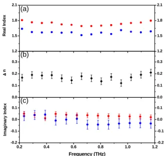
The optical constants of E7 for both the o-ray and e-ray are determined using the method and procedure described in our previous work [9]. In Fig. 2(a), the THz–band extraordinary and ordinary refractive indices of E7 are shown. Clearly, E7 exhibits a positive birefringence (ne >
no), which is consistent with that in the visible range [18]. There is no sharp resonance in the
0.2-1.2 THz range, in which ne varies from 1.69 to 1.80, while no varies from 1.51 to 1.63. The
birefringence of E7 is thus 0.12 to 0.21 for the same frequency range (see Fig. 2(b)). This is comparable to that of 5CB and much larger than that of PCH5 (∆n ~ 0.08) [10, 19]. The corresponding imaginary indices of E7 are relatively small (< 0.04, see Fig. 2(c)). That is, the extinction coefficient of E7 is less than2 cm-1. Thus E7 exhibit high birefringence, small losses
and broad nematic temperature range, which are attractive for applications such as phase shifting. 0.2 0.4 0.6 0.8 1.0 1.2 -0.2 -0.1 0.0 0.1 -0.2 -0.1 0.0 0.1 0.0 0.1 0.2 0.3 0.0 0.1 0.2 0.3 Im a g in ar y I n d e x Frequency (THz) (a) (c) ∆ ∆ ∆ ∆ n 1.2 1.5 1.8 2.1 1.2 1.5 1.8 2.1 (b) R e a l I nde x
Fig. 2. The room-temperature (a) extraordinary (red circles) and ordinary (blue circles) refractive indices, (b) birefringence, and (c) imaginary extraordinary (blue circles) and ordinary (red circles) refractive indices of E7 are shown as a function of frequency between 0.2 to 1.2 THz.
4. The tuning of phase in the THz range
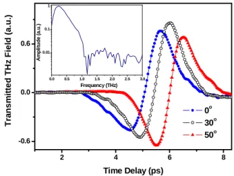
The temporal THz profiles passing through the LC phase shifter at various magnetic inclination angles (θ = 0°, 30° and 50°) are shown in Fig. 3. The spectrum of the THz signal at θ = 0° is
from1 to 8.3 ps are shown. The transmitted THz waves show obviously longer time delay for larger angle, θ.The THz field amplitudes increase with θ for θ < 43º. This can be explained by the increasing transmittance at the quartz-LC interface according to the Fresnel equations [20]. The ordinary and extraordinary refractive indices of E7 are 1.57 and 1.76, respectively, at 1 THz. With increasing θ, the effective refractive index of LC will rise from 1.57 to 1.76 and become closer to the refractive index of quartz substrate, which is 1.95. The transmitted field amplitudes will then increase according to Fresnel equations. The THz field amplitudes decrease for θ > 43º due to partial blocking of the THz wave by the magnet.
2 4 6 8 -0.6 0.0 0.6 0.0 0.5 1.0 1.5 2.0 2.5 3.0 0.01 0.1 1 Am pl it u d e ( a .u .) Frequency (THz) Tra n s m it te d TH z Fie ld (a .u. ) Time Delay (ps) 0o 30o 50o
Fig. 3 . The measured THz waveforms transmitted through the LC phase shifter at various magnetic inclination angles. The inset shows the spectrum of the THz signal.
The spectral amplitude and phase of the transmitted THz wave are deduced from the temporal waveforms by fast Fourier transform (FFT) algorithms.The deduced phase shifts are plotted as a function of the magnetic inclination angle in Fig. 4 for 0.49 and 1.025 THz waves. The THz waves experience larger phase shift at higher frequencies as expected from Eq. (1). The maximum phase shift achieved was 368º at 1.025 THz and θ = 54º.
The threshold field required to reorient LC molecules in our LC cell when the magnetic field is perpendicular to the alignment direction is less then 0.01 T,[12] which is much lower than the magnetic field employed in this work (~ 0.43 T). This means that Eq. (2) is valid and can be used to predict the phase shifts. With Eq. (2) and the measured indices of E7, we have calculated the theoretically predicted phase shifts, which are also plotted as the solid curves in Fig. 4. They show good agreements with the experimental results.
0 10 20 30 40 50 60 0 50 100 150 200 250 300 350 400 Ph ase Sh if t ( d eg rees) θθθθ (degrees) 1.025 THz 0.49 THz theoretical 368o
Fig. 4. The phase shift of the THz waves versus the magnetic inclination angle. The solid curves are theoretical predictions. The red and blue circles are experimentally measured phase shift at 0.49 and 1.025 THz.
5. Summary
In summary, we have demonstrated a room temperature THz phase shifter by using a sandwiched LC cell. A maximum phase shift of 360º at 1 THz has been achieved successfully. The phase shift can be tuned magnetically by controlling the effective refractive index of LC layer. Measured results are in agreement with theoretical predictions. We also report the optical constants and birefringence of E7 in the frequency range of 0.2 – 1.2 THz.
Acknowledgments
This work was supported in part by the National Science Council of R.O.C. under Grants No. NSC 92-2215-E-009-030 and the Program for Pursuit of Academic Excellence in Universities of the Ministry of Education, R.O.C.