Liquid crystal terahertz photonics with indium tin oxide nanowhiskers
and graphene as functional electrodes
Chan-Shan Yang
a, Ru-Pin Pan
b, Ci-Ling Pan*
aa
Dept. of Physics, National Tsing Hua Univ., Hsinchu, 30013 Taiwan;
bDept. of Electrophysics,
National Chiao Tung Univ., Hsinchu, 30010 Taiwan
ABSTRACT
We have constructed and characterized THz phase shifters based on liquid crystals (LCs) with graphene grown by chemical vapor deposition (CVD) and indium-tin-oxide nanowhiskers (ITO NWhs) as transparent conducting electrodes. A graphene-based phase shifter can achieve a phase shift of π/2 at 1.0 THz with the operating voltage of ~2.2 V (rms) as opposed to ~ 5.6 V (rms) for ITO-NWhs-based phase shifter in previous work. On the other hand, 2π phase shift at 1.0 THz was achieved in an ITO-NWhs-based phase shifter with a multi-sandwiched structure by applying ~2.6 V (rms). The low operation voltage of both two kinds of phase shifters imply compatibility of both type of devices with thin-film transistor (TFT) and complementary metal-oxide-semiconductor (CMOS) technologies. The experimental results of phase shifters are in good agreement with the theoretical predictions.
Keywords: Far infrared or terahertz, phase shift, liquid-crystal devices, spectroscopy, terahertz, transparent conductive
coatings
1. INTRODUCTION
During the last three decades, remarkable progress has been made in sub-millimeter or terahertz (THz) technology, which has made significant inroads to applications in fields ranging from bio-medicine, 3D imaging, tomography, and characterization of materials.1 Sub-THz radio-over-fiber communication at data rate exceeding 20Gb/s over a 25km fiber
link was also demonstrated.2 To meet the demands of the exploding THz field, many novel quasi-optic components, such
as phase shifter,3-7 phase grating,8 polarizers,9,10 and filters11-14 have been developed. In particular, a number of tunable
THz devices employing liquid crystals (LCs) have attracted considerable attention.3-9,11,12,14 Besides , a LC spatial THz
modulator (STM) with an ability of tuning THz wave front is a key component to achieve the THz vortex system which can make the conversion of orbital angular momentum.15
1.1 Terahertz phase shifter
In our previous work, phase shift exceeding /2 at 1 THz was achieved by using electrically controlled birefringence in a 570 m-thick homeotropically aligned (E7) LC cell, biased at a root-mean-square voltage of 125 V (rms). Sputtered indium-tin-oxide (ITO) films, widely used as electrodes in visible range, are opaque in the THz frequency range.16,17
Therefore, two copper pieces separated by ~ 11 mm on two sides of LCs cell were used as spacers and electrodes.4 Later,
X.-W. Lin et al. demonstrated a /3 phase shifter by using sub-wavelength metallic gratings as the transparent electrodes. Its operative voltage was, however, as high as 130 V (rms).6 Clearly, novel materials serving as transparent
electrodes for the THz frequency band need be developed. Indeed, a THz phase shifter utilizing graphene and LCs showed excellent transmittance.7 The maximum phase shift of this device, however, was just 10.8 degrees at a driving
voltage of 5 V.
1.2 Complex electrical characterization of indium-tin-oxide nanowhiskers (ITO NWhs) and graphene
Recently, ITO nanomaterials, e.g. nanocolumn, nanorods (NRs), nanowires, and nanowhiskers (NWhs), were reported to have omnidirectional, broadband anti-reflective (AR) characteristics in the visible and near-infrared, as well as superhydrophilicity. These nanomaterials are thus useful as electrodes in solar cells, light emitting diodes (LEDs), and displays. Previously, we showed that ITO NWhs is also highly transparent (~82%) in the THz band. Furthermore, their DC mobility (~92 cm2V-1s-1) and conductivities (~ 245 -1cm-1) are comparable to sputtered ITO thin films.16-18
Graphene is the first strictly two-dimensional material. The electrical mobility of monolayer graphene is as high as ~10,000 cm2V-1s-1) at room temperature. The transmittance of graphene is outstanding not only in the visible, but also at
THz frequencies.7 Besides, it also exhibits high chemical stability and mechanical strength. Such unique properties make
graphene an attractive optoelectronic material. Complex conductivities of the graphene samples can be extracted from THz time-domain spectroscopic (THz-TDS) measurements and fitted with the Drude free-electron model. Electrical properties of the samples, such as plasma frequency (ωp), scattering time (τ), dc mobility (μ), and dc conductivity (σo),
are obtained. Recently, our group just shows the mobility of CVD-grown graphene used in this work is ~4000 cm2/Vs.
Comparing to the ITO NWhs, another promising candidate as transparent conductor for THz optoelectronic devices, graphene has lower transmittance but much higher conductivity and mobility.
In this work, we review out recent works and further development on Liquid crystal terahertz phase shifters with indium tin oxide nanowhiskers and graphene as functional electrodes19, 20. It will be shown that ITO NWhs obliquely
evaporated by electron-beam glancing-angle deposition can serve simultaneously as transparent electrodes and aligned layer of LCs in a terahertz (THz) phase shifter. Besides, a graphene-based phase shifter can achieve a phase shift of π/2 at 1.0 THz with the operating voltage of ~2.2 V (rms) versus ~ 5.6 V (rms) for ITO-NWhs-based phase shifter in previous work. On the other hand, 2π phase shift at 1.0 THz was achieved in an ITO-NWhs-based phase shifter with a multi-sandwiched structure by applying ~2.6 V (rms). The voltage and frequency-dependent characteristics of the THz phase shifter are discussed in detail.
2. THEORY AND EXPERIMENT
2.1 Theoretical Principles
In the following, we briefly review the theoretical basis of effects of electrically-induced birefringence in a homogeneously aligned liquid crystal cell on THz waves traversing it. The boundary conditions on internal surfaces of substrates for the LC cell require that the tilt angle of the director, (0) = (d) = 0, at the inner faces of the cell. Further, LC molecules are assumed to be originally aligned along the x-direction. The condition for minimum free energy (U = 0) can be written as: 19, 20
2 22 2
1 3 2 2
/ /
cos sin constants
( sin cos ) z D d k k dz
, (1)where k3, , Dz, //, and are the bend elastic constant, tilt angle, the z component of the displacement field vector, the
dielectric constants which are along the preferred axis and perpendicular to this axis, respectively. After assuming the maximum tilt angle, max, at the position of d/2, and defining the threshold voltage, Vth (k1/(0))1/2, where 0 =
8.85410-12 Fm-1, , k
1, and d are free-space permittivity, dielectric anisotropy, splay elastic constants, and the distance
between two electrodes, respectively. For E7, and k1 are 13.8, and 11.110-12 N, respectively; for MDA-00-3461,
they are 11.2, and 12.610-12 N, respectively. The relationship between
max and the applied voltage can be derived
as,19,20
2 2 2 max max 2 0 2 2 2 2 max max1 sin sin 1 sin
2
1 sin sin 1 sin sin th
V d V
, (2)where = (k3-k1)/k1, = (//-)/, and V is the applied voltage, whereas sin = sin /sin max. Besides, Vth is the
threshold voltage, and equals to Ethd. After finding the max at every applied voltage, the effective birefringence
experienced by the THz wave transmitting through the LC cell can be written as,19,20 n
eff.Max=cos2max/no2
sin2
max/ne2-1/2- no,1, 3 where ne and no are extraordinary and ordinary indices of refraction of the LC, respectively.
Because of the ~500 m-thick cell, we can write the phase shift due to the effective birefringence as = 2fdneff.Max/c, where f and c are the frequency and speed of propagation of the THz wave in vacuum. Here, the values
of ne and no for E7 are 1.690~1.704 and 1.557~1.581 at 26ºC, respectively, giving rise to a birefringence of 0.130~0.148
in this frequency range.21 For MDA-00-3461, the values of n
e and no are ~1.75 and 1.55, respectively. Indeed, the
aforementioned model is used for thin liquid crystal cell (~20 μm), operating in visible frequency range. However, the THz phase shifter is quite thick. In this work, the thickness of LC layer for 2 phase shifter is around 1.12 mm. Ideally, almost all of the LC molecules orientate along the z direction, parallel to the external electric field, in the presence of high applied voltage. This is never the case experimentally. Therefore, we apply a factor, , for thickness compensation. The factor is determined by Eq.(3), where Vmax =70 V. On the other hand, we also found the presence of a pretilt angle in
I))
14311 nm
ITO-NWhs-based phase shifters. Therefore, we modify the model by applying the compensation factor, , which can be determined by Eq.(4), where E
E is experimental phase shift. Combining both thickness and pretilt compensationfactors, the effective phase shift is expressed as Eq.(5)
max 0 2 f ne no d c V
, (3)
0 E max 2 e o c d V f n n
, (4) eff
, (5)2.2 Preparation of substrates with ITO nanomaterials or graphene
ITO nanomaterials, e.g., nanowires, nanorods and nanowhiskers, were deposited using the Electron-Beam Glancing-Angle Deposition (GLAD) technique, as described in our previous works. 16-18 It was determined that ITO Whs with
height of about 1000 nm is most suitable for the applications such as transparent electrodes for THz devices. Here, the These are shown In Fig. 1(a), and Fig. 1(b), respectively, we show tilted top view and cross-sectional images of ITO NWhs with height of about 1430 nm, as examined by scanning electron microscopy (SEM)..
Figure 1. (a) The tilted top SEM view and (b) the corresponding cross-sectional image of the ITO NWhs. (adapted from Ref. [20])
In the other set of experiments, single or bi-layer graphene samples were grown on fused silica substrates by chemical vapor deposited graphene. The detailed growth parameters and the transfer procedures can be found in the previous publications.22 Two-layer graphene samples were obtained by repeating transfer processes twice on the same
silica substrates. Following the transfer, Cr/Au (5 nm/20 nm) gate electrodes were deposited to make ohmic contact to graphene. We use Raman spectroscopy (632 nm wavelength) to exam the quality of single-layer graphene transferred onto silica substrate. The G and 2D peaks were found to be positioned at ~1580 cm-1 and ~2650 cm-1 respectively. Their
intensity ratio, I2D/IG ~1.8, indicates that the quality of single-layer graphene on silica substrate is comparable with those
prepared in earlier works.22
2.4 THz time-domain spectroscopy (THz-TDS)
The photoconductive (PC) antenna-based THz-TDS as described in our previous works were used to characterize the devices in the frequency range between 200 GHz and 1.4 THz.16 Two pairs of symmetrically placed parabolic mirrors
with focal lengths of 7.5 and 15 cm were employed. Their diameters of long versus short axis are 7 versus 5 cm, and 10 versus 7 cm, respectively. The dynamic range of our THz-TDS is as high as 106. During measurements, the THz-TDS
system was purged with nitrogen at a relative humidity of 4.5 0.5.
3. TERAHERTZ PHASE SHIFTER USING INDIUM-TIN-OXIDE NANOMATERIALS AS
FUNCTIONAL ELECTRODES
3.1 Indium-tin-oxide nanostructures for aligning LCs
Conventionally, homeotropic or homogeneous alignments of liquid crystal (LC) was achieved by coating or mechanically rubbing the substrate with suitable polyimides, respectively. Drawbacks of the above so-called contact methods include electrostatic damage, residual stress, cosmetic defect, and dust pollution.23 Therefore, many groups
=r
oxide (SiOx), TiO2, MgF2, Al2O3, and metals can result in film growth in a preferred direction of LCs molecules.24-30
Later, it is shown that the pretilt angle and orientation of LC director depends on the angle of evaporation of these materials.26,29 However, few materials which can simultaneously function as transparent conductor and aligning
mechanism for LC molecules have been disclosed to date. A schematic illustration of the geometric relationship between the evaporation direction and director orientation of the nematic LC is presented in Fig. 2 The plane of incidence of THz wave is defined as the y-z plane. The angle between the z-axis (normal to the substrate) and evaporation direction, or the evaporation angle, is 70. Besides, is the angle of inclination of the ITO NWhs from surface normal of the substrate. As a boundary condition of LC aligned by the evaporation method, the orientation of the nematic LCs is assumed to be along the x-axis, which is perpendicular to the plane of incidence of the THz wave. According to the analysis of L. A. Goodman et al.,26 orientation of LC molecules which are perpendicular to the plane of incidence (along the x-axis)
requires the lowest elastic deformation energy. Therefore, it should be the preferred orientation of LCs molecules.26 T.
Uchida et al. showed that evaporation angles of SiO in the range of 70~80 can reorient the LC molecules along the x-axis.29 The similar phenomenon was observed in this work.
Figure 2. The schematic illustration of the geometric relationship between the evaporation direction and director orientation of the nematic LCs. (adapted from Ref. [20])
3.2 THz quarter-wave plate
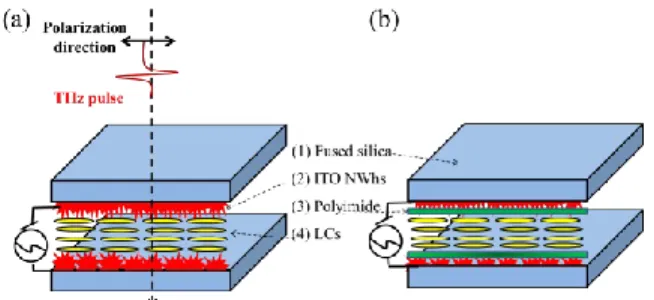
The configurations of THz phase shifters studied in this work are shown in Figs. 3(a) and 3(b). The cells were constructed by sandwiching the LC (E7 by Merck) layer between two fused silica substrates which were deposited with ITO NWhs by the electron-beam glancing-angle deposition (GLAD) method. For the phase shifters in Fig. 3(a) and 3(b), the thicknesses of the fused silica substrate and the LCs layer are 9596 and 51715 m, versus 10088 m, and 50912 m, respectively. The mechanisms of LC alignment for the devices in Fig. 3(a) and 3(b) are different. For the device shown in Fig. 3(b), the inner surfaces of both ITO NWhs-deposited substrates were further coated with polyimide (PI) alignment layers, which were lacking for the devices in Fig. 3(a). Note that these are thick cells, which are much thicker than LC cells used in optical devices. This is due to the path length requirement for phase shifting at THz frequencies.
Figure 3. Schematic drawing of THz phase shifter (a) without polyimide (PI), and (b) with PI. (adapted from Ref. [20]) Before undertaking the phase shifting experiments, we first checked the alignment condition of these LC cells by placing the cell between a pair of crossed polarizers. Dark (the director of LCs is parallel to one of the polarizers) and bright (the director of LCs is 45 to crossed polarizers) states for the device shown in Fig. 3(a) are shown in Fig. 4(a), and 4(b), while those for device drawn in Fig. 3(b) are presented in Fig. 4(c) and 4(d), respectively. For the device with PI (Fig. 3(b)), even though the LC layer is thick, we were able to achieve uniform alignment with high contrast (see Figs.
- * - *
- ----*
---4, !* !
4(c) and 4(d)). For the device without the PI, although the alignment was not as well as that with the PI, we were still able to observe high-contrast images for bright and dark states (see Figs. 4(a) and (b)).
Figure 4. The (a) and (b) are the dark and bright states of the THz phase shifter without PI; the (c) and (d) are of with PI. (adapted from Ref. [20])
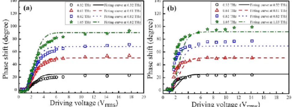
Fig. 5(a) and (b) exhibit the phase shift as a function of driving voltage for the devices with PI, and without PI, respectively. Over 90 of phase shifters were achieved at 1.05 THz when the devices with PI and without PI were driven at 17.68, and 2.83 V (rms), respectively. The fitting curves are theoretical predictions according to Eq. (1)-(3). Far above threshold, the LCs molecules are essentially aligned with the electric field. For the THz phase shift with PI, the theoretical curves are in good agreements with the experiments, and the Eth and corresponding Vth are determined as
18.60 V/cm and 0.95 V (rms), respectively. However, for the THz phase shift without PI, the maximum phase shifts of theoretical curves in the different frequencies are generally in good agreements with the experiments. However, the discrepancy below ~4 V (rms) is considerable. This can be attributed to the weak anchoring of the LC aligned by ITO NWhs only, which results in the reduction of operating voltages and the drastic change in the electro-optic response.31 In
order to understand the level of weak anchoring on the ITO NWhs surface, further studies are required. Meanwhile, the thresholds for voltage and electric field, Vth and Eth are determined to be 0.71 V (rms) and 13.73 V/cm, respectively,
slightly lower than the theoretically predicted values, 0.95 V (rms) and 18.32 V/cm.
Figure 5. Phase shifter as a function of driving voltages for four frequencies of THz phase shifters (a) with PI, and (b) without PI, respectively. (adapted from Ref. [19], and Ref. [20], respectively)
3.3 2 liquid crystal terahertz phase shifter
As the configuration of phase shifters shown in Fig. 6, the phase shifters were constructed by multi-sandwiching the LC (MDA-00-3461 by Merck) layers between fused silica substrates which were deposited with ITO NWhs and spin-coated by polyimide layer as transparent electrodes and alignment layer, respectively. The thickness of substrate is about 1.033 mm, while that of LC layer is limited to ~1.12 mm in order to align the LCs by rubbed polyimide layer, that is, the total thickness of LC layer for each sample is about 2.24 mm. The cells were biased with sinusoidal signals at 1 kHz. We designed three different constructions of THz phase shifter, 4-layer-ITO-NWhs means that the sample was applied four pieces of substrate deposited with ITO NWhs. Similarly, the other two cells are applied three and two pieces of ITO-NWhs substrates, respectively.
,
,
q s,
/
| ¡{
! . r,Figure 6. Schematic diagrams of three different designs of ITO-NWhs-based phase shifter. (a) 4-layer-ITO-NWhs, (b) 3-layer-ITO-NWhs, and (c) 2-layer-ITO-NWhs cell.
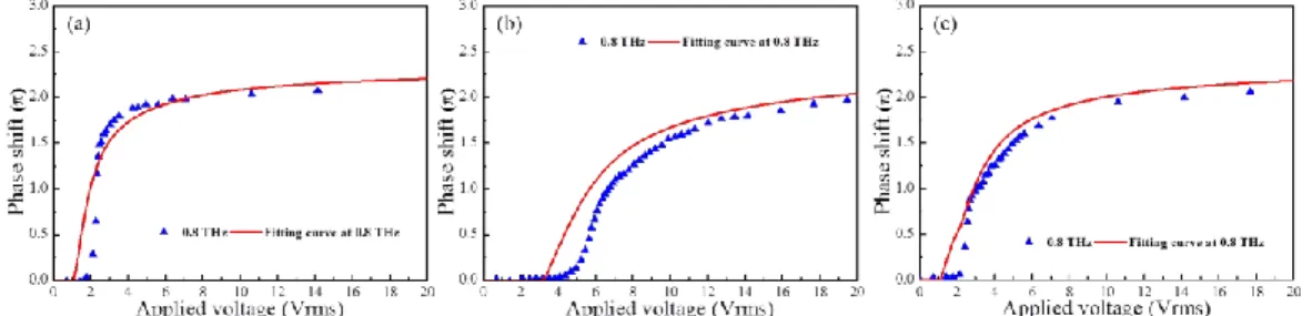
The phase shift as a function of driving voltage is shown in Fig. 7, where the fitting curves are corresponding theoretical predictions according to Eqs. (1)–(5). Here, the experimental results of phase shifters are in good agreement with the theoretical predictions. The operating voltage for achieving a phase shift of 2π at 1.0 THz and the averaging transmittance of the phase shifters are shown in Table 1.
Figure 7. Phase shift as a function of applied voltage of (a) 4-layer-ITO-NWhs, (b) 3-layer-ITO-NWhs, and (c) 2-layer-ITO-NWhs phase shifter.
Table 1. The operating voltage for achieving a phase shift of 2π at 1.0 THz and the averaging transmittance of three
kinds of phase shifters.
Electrode layer number Averaging transmittance Operating voltage for 2π phase shift
4-layer 20.0% 2.6 V
3-layer 25.4% 5.3 V
2-layer 31.3% 10.3 V
4. TERAHERTZ PHASE SHIFTER EMPLOYING GRAPHENE AS TRANSPARENT
ELECTRODES
4.1 THz quarter-wave plate
The phase shifters were constructed by sandwiching the LC (MDA-00-3461 by Merck) layer between two fused silica substrates with transferred graphene and spin-coated polyimide layer as electrodes and alignment layer, respectively. The configuration of phase shifter is shown in Fig.8, where the thickness of substrate and LC layer are about 1.033 and 0.55 mm, respectively. The cells were biased with sinusoidal signals at 1 kHz.
I:iO_4 0.4 40 4103 02 0.1 o.o 0 1/161111t-Rgir:a..st6s7116s 2 4 6 8 16 12 14 16 18 70
A,jIj11iFXll VOIÍ)l1: eiIIgB)
Figure 8. Schematic diagrams of liquid crystal THz phase shifter, applying graphene as transparent electrodes.
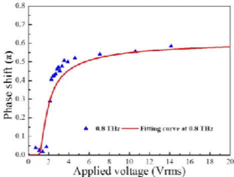
The phase shift as a function of driving voltage is shown in Fig. 9, where the fitting curves are corresponding theoretical predictions according to Eqs. (1)–(5). Here, the experimental results of phase shifters are in good agreement with the theoretical predictions. The operating voltage for achieving a phase shift of π/2 at 1.0 THz of the monolayer and bilayer graphene-based phase shifters are about 2.6 and 2.2, respectively. Besides, the averaging transmittance of two LC cells are about 38.1% and 36.6%, respectively.
Monolayer graphene shows higher dc conductivity, mobility, and transmittance than that of bilayer one. Furthermore, monolayer has relatively low cost. Therefore, monolayer graphene is more suitable for the applications in THz regime than bilayer one.
Figure 9. Phase shift as a function of applied voltage of phase shifter with bilayer graphene electrodes.
5. SUMMARY
In summary, we have constructed and characterized THz phase shifters based on LCs with graphene grown by CVD and ITO NWhs obliquely evaporated by electron-beam GLAD as transparent conducting electrodes. A graphene-based phase shifter can achieve a phase shift of π/2 at 1.0 THz with the operating voltage of ~2.2 V (rms) versus ~ 5.6 V (rms) for NWhs-based phase shifter in previous work. On the other hand, 2π phase shift at 1.0 THz was achieved in an ITO-NWhs-based phase shifter with a multi-sandwiched structure by applying ~2.6 V (rms). The low operation voltage of both two kinds of phase shifters imply the compatibility with TFT and CMOS technologies. The experimental results of phase shifters are in good agreement with the theoretical predictions.
6. ACKNOWLEDGMENTS
This work was partially supported by grant 101-2221-E-007-103-MY3 of the National Science Council, and the Academic Top University Program of the Ministry of Education, Taiwan, as well as U. S. Air Force Office of Scientific Research, AOARD FA2386-13-1-4086. The authors would like to thank C. Kuo for the help of many measurements, and Dr. Tsung-Ta Tang for many discussions. They would also like to thank Prof. Peichen Yu, Prof. J. C. Chen, Dr. C.-C. Tang, and P.-H. Chen for the preparation of substrates with ITO nanostructures and graphene, respectively.
7. REFERENCES
[1] Zhang, X.-C. and Xu, J., Introduction to THz Wave Photonics, New York: Springer, 2010.
[2] Shi, J.-W., Huang, C.-B. and Pan, C.-L., “Millimeter-wave photonic wireless links for very-high data rate communication,” NPG Asia Materials 3(2), 41-48 (2011).
[3] Chen, C.-Y., Hsieh, C.-F., Lin, Y.-F., Pan, R.-P. and Pan, C.-L., “Magnetically tunable room-temperature 2 liquid crystal terahertz phase shifter,” Opt. Express 12, 2630-2635 (2004).
[4] Hsieh, C.-F., Pan, R.-P., Tang, T.-T., Chen, H.-L. and Pan C.-L., “Voltage-controlled liquid-crystal terahertz phase shifter and quarter-wave plate,” Opt. Lett. 31, 1112-1114 (2006).
[5] Wu, H.-Y., Hsieh, C.-F., Tang, T.-T., Pan, R.-P. and Pan C.-L., “Electrically tunable room-temperature 2 liquid crystal terahertz phase shifter,” IEEE Photonic Technol. Lett. 18, 1488-1490 (2006).
[6] Lin, X.-W., Wu, J.-B., Hu, W., Zhenh, Z.-G., Wu, Z.-J., “Self-polarizing terahertz liquid crystal phase shifter,” AIP Advances 1, 032133 (2011).
[7] Wu, Y., Ruan, X., Chen C.-H., Shin, Y. J., Lee Y., Niu, J., Chen Y., Yang, K.-L., Zhang, X., Ahn, J.-H. and Yang H., “Graphene/liquid crystal based terahertz phase shifters,” Opt. Express 21, 21395 (2013).
[8] Lin, C.-J., Li, Y.-T., Hsieh C.-F., Pan, R.-P. and Pan C.-L., “Manipulating terahertz wave by a magnetically tunable liquid crystal phase grating,” Opt. Express 16, 2995-3001 (2008).
[9] Hsieh, C.-F., Lai, Y.-C., Pan, R.-P. and Pan C.-L., ”Polarizing terahertz waves with nematic liquid crystals,” Opt. Lett. 33(11) 1174-1176 (2008).
[10] Ren, L., Pint, Pint, C. L., Booshehri, L. G., Rice, W. D., Wang, X., Hilton, D. J., Takeya, K., Kawayama, I., Tonouchi, M., Hauge, R. H. and Kono J., “Carbon nanotube terahertz polarizer,” Nano Lett. 9(7), 2610-2613 (2009).
[11] Chen, C.-Y., Pan, C.-L., Hsieh C.-F., Lin Y.-F. and Pan, R.-P., “Liquid-crystal-based terahertz tunable Lyot filter,” Appl. Phys. Lett. 88, 101107 (2006).
[12] Ho, I.-C., Pan, C.-L., Hsieh, C.-F. and Pan, R.-P., “Liquid-crystal-based terahertz tunable Solc filter,” Opt. Lett. 33(13), 1401-1403 (2008).
[13] Chiang, Y.-J., Yang, C.-S., Yang, Y.-H., Pan, C.-L., and Yen, T.-J., “An ultrabroad terahertz bandpass filter based on multiple-resonance excitation of a composite metamaterial,” Appl. Phys. Lett. 99, 191909 (2011).
[14] Vieweg, N., Born, N., Al-Naib, I. and Koch, M., “Electrically tunable terahertz notch filter,” J. Infrared Milli. Terahz Waves 33, 327-332 (2012).
[15] Xie, Z., Wang, X., Ye, J., Feng, S., Sun, W., Akalin, T. and Zhang, Y., “Spatial terahertz modulator,” Scientific report 3, 3347 (2013).
[16] Yang, C.-S., Lin, M.-H., Chang, C.-H., Yu, P., Shieh, J.-M., Shen, C.-H., Wada, O. and Pan, C.-L., “Non-Drude behavior in indium-tin-oxide nanowhiskers and thin films by transmission and reflection THz time-domain spectroscopy,” IEEE J. Quantum Electron. 49(8), 677-690 (2013).
[17] Yang, C.-S., Chang, C.-M., Chen, P.-H., Yu P. and Pan, C.-L., “Broadband terahertz conductivity and optical transmission of indium-tin-oxide (ITO) nanomaterials,” Opt. Express 21(14), 16670-16682 (2013).
[18] Yang C.-S., Chang, C.-H., Lin, M.-H., Yu, P., Wada, O. and C.-L. Pan, “THz conductivities of indium-tin-oxide nanowhiskers as a graded-refractive-index structure,” Opt. Express 20, A441 (2012).
[19] Yang, C.-S., Tang, T.-T., Chen, P.-H., Pan, R.-P., Yu, P. and Pan, C.-L., “Voltage-controlled liquid-crystal terahertz phase shifter with indium-tin-oxide nanowhiskers as transparent electrodes,” Opt. Lett. 39(8), 2511-2513 (2014). [20] Yang, C.-S., Tang, T.-T., Pan, R.-P., Yu, P. and Pan, C.-L., “Liquid crystal terahertz phase shifters with functional
[21] Yang, C.-S., Lin, C.-J., Pan, R.-P., Que, C. T., Yamamoto K., Tani, M. and Pan, C.-L., “The complex refractive indices of the liquid crystal mixture E7 in the terahertz frequency range,” Journal of the Optical Society of America B-Optical Physics 27(9), 1866~1873 (2010)
[22] Tang, C.C., Li, M.Y., Li, L. J., Chi, C.C. and Chen, J. C., “Characteristics of a sensitive micro-Hall probe fabricated on chemical vapor deposited graphene over the temperature range from liquid-helium to room temperature,”Appl. Phys. Lett. 99, 112107 (2011)
[23] Liou, W.-R., Chen, C.-Y., Ho, J.-J., Hsu, C.-K., Chang, C.-C., Hsiao, R. Y. and Chang, S.-H., “An improved alignment layer grown by oblique evaporation for liquid crystal devices,” Display 27, 69-72 (2006).
[24] Janning, J. L., "Thin film surface orientation for liquid crystals," Appl. Phys. Lett. 21(4), 173-174 (1972).
[25] Urbach, W., Boix, M. and Guyon, E., "Alignment of nematics and smectics on evaporated films," Appl. Phys. Lett. 25(9), 479-481 (1974).
[26] L. A. Goodman, J. T. Mcginn, C. H. Anderson, and F. Digeronimo, “Topography of obliquely evaporated silicon oxide films and its effect on liquid-crystal orientation,” IEEE Trans. Electron Devices ED-24(7), 795-804 (1977). [27] D. Armitage, “Alignment of liquid crystals on obliquely evaporated silicon oxide films,” J. Appl. Phys. 51(5),
2552-2555 (1980).
[28] W. R. Heffner, D. W. Berreman, M. Sammon, and S. Meiboom, “Liquid crystal alignment on surfactant treated obliquely evaporated surfaces,” Appl. Phys. Lett. 36, 144-146 (1980).
[29] T. Uchida, M. Ohgawara, and M. Wada, “Liquid crystal orientation on the surface of obliquely-evaporated silicon monoxide with homeotropic surface treatment,” Jpn. J. Appl. Phys. 19(11), 2127-2136 (1980).
[30] T. Wilson, G. D. Boyd, E. H. Westerwick, and F. G. Storz, “Alignment of liquid crystals on surfaces with films deposited obliquely at low and high rates,” Mol. Cryst. Liq. Cryst. 94, 359-366 (1983).
[31] G. P. Bryan-Brown, E. L. Wood, and I. C. Sage, “Weak surface anchoring of liquid crystals,” Nature 399, 338-340 (1999).