國
立
交
通
大
學
多媒體工程研究所
碩 士 論 文
利用以預測為基礎的可逆性映射之新資訊隱藏
技術與其在視訊監控與偽裝學上之應用
A Study on New Data Hiding Techniques Using Reversible
Prediction-based Mappings for Video Surveillance and
Steganography Applications
研 究 生:林采韻
指導教授:蔡文祥 教授
利用以預測為基礎的可逆性映射之新資訊隱藏技術與其在
視訊監控與偽裝學上之應用
A Study on New Data Hiding Techniques Using Reversible
Prediction-based Mappings for Video Surveillance and
Steganography Applications
研
究 生:林采韻 Student:Tsai-Yun Lin
指導教授:蔡文祥
Advisor:Wen-Hsiang Tsai
國 立 交 通 大 學
多 媒 體 工 程 研 究 所
碩 士 論 文
A ThesisSubmitted to Institute of Multimedia Engineering College of Computer Science
National Chiao Tung University in partial Fulfillment of the Requirements
for the Degree of Master
in
Computer Science
June 2011
Hsinchu, Taiwan, Republic of China
i
利用以預測為基礎的可逆性映射之新資訊隱藏技術與
其在視訊監控與偽裝學上之應用
研究生:林采韻
指導教授:蔡文祥 博士
國立交通大學多媒體工程研究所
摘要
隨著數位攝影機技術的快速發展,有越來越多的監控攝影機架設在日常生活 環境中,這些視訊監控系統對於個人隱私權所造成的威脅日益受到關注。本論文 利用資訊隱藏技術,對監控影像中的隱私區域做保護與偽裝之研究。首先,本論 文提出一個新方法可用以保護視訊監控影片中指定隱私區域的影像,該法利用可 逆的映射函式,將隱私區域的影像轉變為與背景圖相似的偽裝影像。接著將此方 法延伸到保護視訊監控影片中動態的私密影像部位。此一延伸方法,首先會在每 一監視畫面中偵測移動事件並自動決定一隱私保護區域,再根據此區域內影像的 色調搭配一無接縫的影像接合技術來調整預設背景圖的顏色,使得偽裝影像與原 監視畫面的色調一致。在需要恢復原來的隱私影像部位時,亦可利用此可逆性映 射函式的反函式,將偽裝影像無失真地轉回原來的隱私影像。最後,本論文運用 前述的可逆性映射函式提出一個新的圖像偽裝術。此法可以將一張全彩的秘密圖 像依據指定的目標圖像轉換成偽裝圖像,使得偽裝圖像與目標圖像在視覺上很相 近,而且此方法在不使用額外的資訊下,仍然可以無失真地將偽裝圖像恢復為秘 密圖像。本論文所提出的方法皆可獲致很好的實驗結果,證明其在實際應用上皆 為可行。ii
A Study on New Data Hiding Techniques Using
Reversible Prediction-based Mappings for Video
Surveillance and Steganography Applications
Student: Tsai-Yun Lin
Advisor: Prof. Wen-Hsiang Tsai, Ph. D.
Institute of Multimedia Engineering, College of Computer Science
National Chiao Tung University
ABSTRACT
With the rapid development of digital camera technologies, more and more surveillance cameras are installed in our daily space for various purposes. There is a growing concern that surveillance systems pose threats to privacy. In this study, we integrate information hiding techniques into surveillance systems to propose three methods for the purposes of privacy protection in video surveillance as well as image steganography.
At first, a new method for protecting a selected private region in a surveillance video is proposed, in which reversible prediction-based mappings are used to convert a privacy-sensitive image into a camouflage image which looks similar to a user-selected background image. The method is extended further to conceal private motion activities in surveillance videos, by which motion regions are detected automatically as the privacy-sensitive image parts, and natural and seamless private image hiding are conducted. The reversible mappings guarantee lossless retrieval of the concealed privacy-sensitive image part from the camouflage image, when required.
iii
Moreover, a new method using the above-mentioned reversible prediction-based mappings for image steganography is proposed, which is capable of hiding a full-color secret image into any cover image, as well as recovering the embedded secret image losslessly without using overhead information.
Good experimental results are also presented to show the feasibility of the proposed methods for real applications.
iv
ACKNOWLEDGEMENTS
The author is in hearty appreciation of the continuous guidance, discussions, and support from her advisor, Dr. Wen-Hsiang Tsai, not only in the development of this thesis, but also in every aspect of his personal growth.
Appreciation is also given to the colleagues of the Computer Vision Laboratory in the Institute of Multimedia Engineering at National Chiao Tung University for their suggestions and help during her thesis study.
Finally, the author also extends her profound thanks to her dear mom and dad for their lasting love, care, and encouragement.
v
CONTENTS
ABSTRACT (in Chinese)………..i
ABSTRACT (in English)……….ii
ACKNOWLEDGEMMENTS………iv
CONTENTS………..v
LIST OF FIGURES………...viii
LIST OF TABLES………..xii
Chapter 1 Introduction ... 1
1.1 Background and Motivation ... 1
1.2 General Review of Related Works ... 3
1.3 Overview of Proposed Methods ... 3
1.3.1 Definitions of terminologies ... 4
1.3.2 Brief description of proposed method for protection of selected private regions in surveillance videos using a reversible prediction-based mapping... 6
1.3.3 Brief description of proposed method for protection of private motion activities in surveillance videos using a reversible prediction-based mapping... 6
1.3.4 Brief description of proposed method for reversible image steganography by a prediction-based mapping ... 8
1.4 Contributions ... 10
1.5 Thesis Organization ... 11
Chapter 2 Review of Related Works ... 12
2.1 Review of Techniques for Privacy Protection in Video Surveillance .. 12
2.2 Review of Techniques for Visible Watermarking in Images ... 14
2.3 Review of Techniques for Data Hiding via Images ... 16
2.4 Review of Techniques for Image Steganography ... 18
Chapter 3 Protection of Selected Private Regions in Surveillance
Videos Using a Reversible Prediction-based Mapping ... 21
3.1 Introduction ... 21
3.1.1 Problem definition ... 22
3.1.2 Major idea of proposed method ... 22
vi
3.2.1 Adopted reversible prediction-based mapping ... 24
3.2.2 Algorithms ... 26
3.2.3 The wrap-around problem and a solution ... 28
3.3 Proposed Method for Protecting Selected Private Regions in Surveillance Videos ... 30
3.3.1 Application of reversible prediction-based mapping to privacy protection in surveillance videos... 31
3.3.2 Proposed content-based prediction used in proposed method . 33 3.3.3 Quality improvement in mapping results ... 38
3.3.4 Process for private region concealment ... 41
3.3.5 Process of private region recovery ... 45
3.4 Experimental Results ... 48
3.5 Summary ... 49
Chapter 4 Protection of Private Motion Activities in Surveillance
Videos Using a Reversible Prediction-based Mapping ... 53
4.1 Introduction ... 53
4.1.1 Problem definition ... 54
4.1.2 Major idea of proposed method ... 54
4.2 Proposed Method for Protecting Private Motion Activities in Surveillance Videos ... 55
4.2.1 Adjustment of color differences ... 55
4.2.2 Process of motion-activity concealment ... 67
4.2.3 Process of motion-activity recovery ... 72
4.3 Experimental Results ... 76
4.4 Summary ... 77
Chapter 5 Reversible Image Steganography by Prediction-based
Mapping ... 82
5.1 Introduction ... 82
5.1.1 Problem definition ... 83
5.1.2 Major idea of proposed method ... 85
5.2 Proposed Method for Image Steganography ... 88
5.2.1 Preprocessing of target image before mapping ... 88
5.2.2 Post-processing of camouflage image after mapping ... 91
5.2.3 Secret image hiding process ... 95
5.2.4 Secret image recovery process ... 98
vii
5.4 Summary ...101
Chapter 6 Conclusions and Suggestions for Future Works ... 108
6.1 Conclusions ...108
6.2 Suggestions for Future Works ...109
viii
LIST OF FIGURES
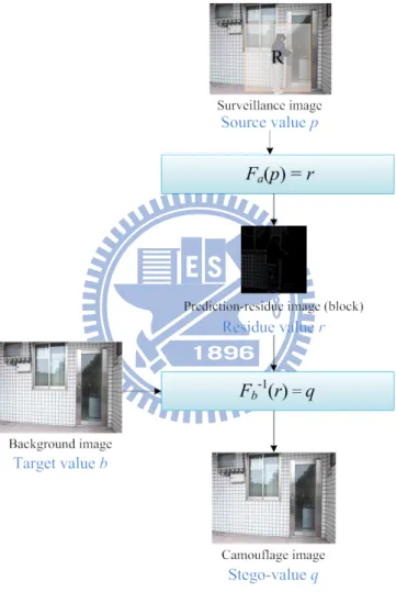
Figure 1.1 Proposed process of protecting selected private regions. ... 7
Figure 1.2 Proposed process of protecting private motion activities. ... 8
Figure 1.3 Image steganography process by using the prediction-based mapping.... 9
Figure 2.1 Examples of privacy protection in video surveillance (a) Dufaux’s video scrambling [4]. (b) Boult’s invertible cryptographic obscuration [5]. ... 13
Figure 2.2 An example of privacy protection by using Hung and Tsai’s method [6]. (a) A privacy-sensitive frame in a video. (b) A privacy-protected frame produced from (a). ... 14
Figure 2.3 Watermarked images by using Liu and Tsai’s method [16]. (a) A watermarked image with a monochrome logo. (b) A watermarked image with a non-uniformly translucent full-color watermark. ... 16
Figure 2.4 Concealment of Morse code (1945) in a picture. The hidden information is encoded onto the grass lengths alongside the river. ... 19
Figure 2.5 An example. (a) A secret image. (b) A result secret-fragment-visible mosaic image created with (a) as a source image. ... 20
Figure 3.1 Illustration of proposed privacy protection of image frames in surveillance video. ... 32
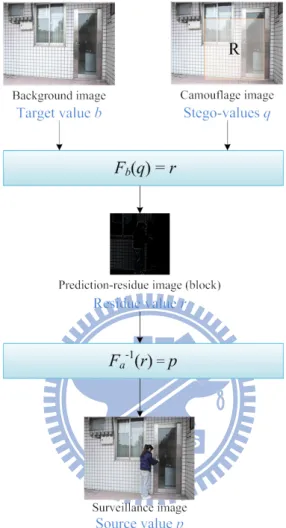
Figure 3.2 Illustration of proposed privacy recovery from image frames in surveillance video. ... 33
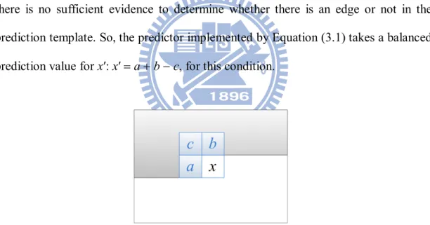
Figure 3.3 The prediction template used in the JPEG-LS standard. ... 35
Figure 3.4 The prediction template used to derive the three candidate prediction values for pixel P with value x. ... 36
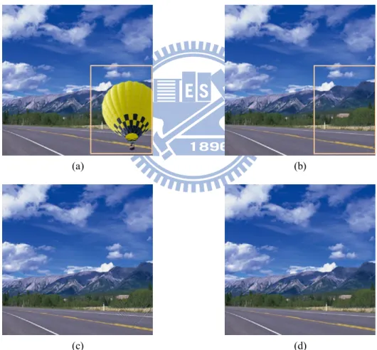
Figure 3.5 An example of quality improvement results. (a) A privacy-sensitive image part enclosed by a rectangle. (b) The pre-selected background image part enclosed by a rectangle used to cover (a). (c) The camouflage image generated from (a) and (b) by using the proposed prediction-based mapping. (d) The camouflage image generated from (a) and (b) by using the proposed quality improvement scheme in the prediction-based mapping process. ... 39
Figure 3.6 An example for computing the side information M of the currently-processed pixel value x. ... 40
Figure 3.7 An example for reducing the prediction residue value. ... 41
Figure 3.8 Flowchart of the proposed private region concealment process. ... 42
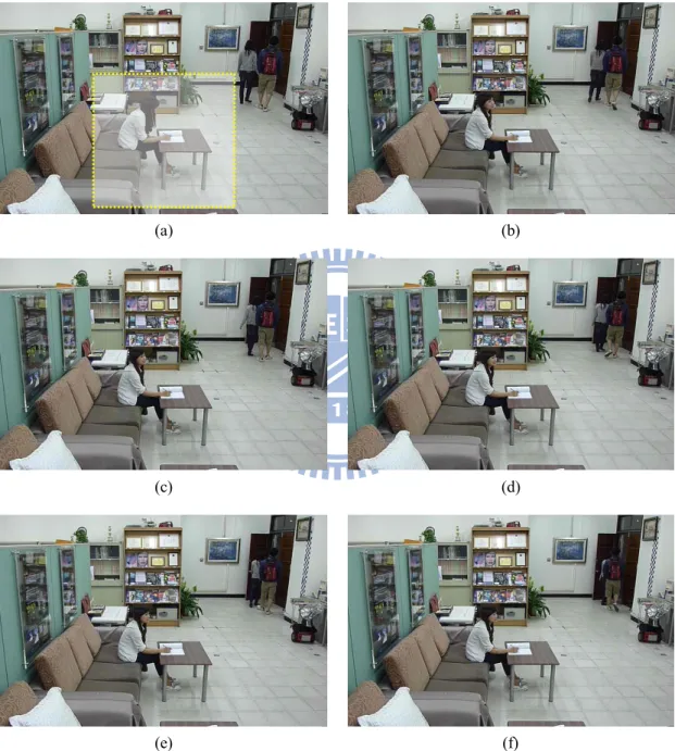
Figure 3.9 Flowchart of the proposed private region recovery process. ... 46 Figure 3.10 Six representative frames of a surveillance video. (a) The first frame with
ix
the protected region enclosed by a rectangle. (b) The second frame. (c) The third frame. (d) The 4th frame. (e) The 5th frame. (f) The 6th frame. 50
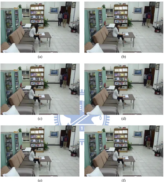
Figure 3.11 Six representative frames of a privacy protected video. (a) The first frame. (b) The second frame. (c) The third frame. (d) The 4th frame. (e) The 5th frame. (f) The 6th frame. ... 51 Figure 3.12 Six representative frames of a recovered video. (a) The first frame. (b) The second frame. (c) The third frame. (d) The 4th frame. (e) The 5th frame. (f) The 6th frame. ... 52 Figure 4.1 An example of results of protecting private motion activities. (a) The
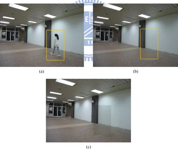
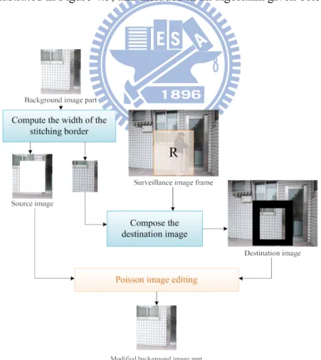
privacy-sensitive image part enclosed by a rectangle. (b) The pre-selected background image part enclosed by a rectangle. (c) The camouflage image generated from (a) and (b) using the proposed private region concealment process. ... 57 Figure 4.2 An example of the proposed method for selecting the target pixel set used to derive the mean and standard deviations. (a) The pixels with yellow color are selected as the target pixel set. (b) The pixels with blue color are selected as the source pixel set. ... 59 Figure 4.3 Illustration of proposed idea for eliminating the visible stitching seams in the camouflage image. ... 60 Figure 4.4 An example of seamless image stitching result. (a) A source image part enclosed by a yellow outline. (b) The destination image part enclosed by a yellow outline. (c) A result generated from (a) and (b) by superimposing (b) on (a) directly. (d) A result generated from (b) by smooth completion. (e) A result generated from (a) and (b) by using the algorithm of Poisson image editing [30]. ... 61 Figure 4.5 Illustration of proposed method for generating a new background image.
63
Figure 4.6 A result of the proposed scheme for detecting moving objects and deciding protected region. (a) A background image. (b) A foreground image. (c) The difference image obtained after a subtracting process. (d) The resulting binary image obtained by selecting protected region, with the protected region enclosed by enclosed by a yellow rectangle. ... 66 Figure 4.7 Flowchart of the proposed motion-activity concealment process. ... 67 Figure 4.8 Flowchart of the private motion-activity recovery process. ... 73 Figure 4.9 Six representative frames of a surveillance video with the protected
regions enclosed by rectangles. (a) The background image frame. (b) The second frame. (c) The third frame. (d) The 4th frame. (e) The 5th frame. (f)
x
The 6th frame. ... 78 Figure 4.10 Six representative frames of a privacy protected video by the previous
concealment process proposed in Chapter3. (a) The background image frame. (b) The second frame. (c) The third frame. (d) The 4th frame. (e) The 5th frame. (f) The 6th frame... 79 Figure 4.11 Six representative frames of a privacy protected video by using the
modified version of the concealment process proposed in this chapter. (a) The background image frame. (b) The second frame. (c) The third frame. (d) The 4th frame. (e) The 5th frame. (f) The 6th frame. ... 80 Figure 4.12 Six representative frames of a recovered video. (a) The background image frame. (b) The second frame. (c) The third frame. (d) The 4th frame. (e) The 5th frame. (f) The 6th frame... 81 Figure 5.1 Illustration of proposed method for image steganography by a
prediction-based mapping. ... 83 Figure 5.2 Illustration of proposed secret image recovery from stego-image. ... 84 Figure 5.3 A result of the second possible solution for the issue of blinding the target image. (a) A secret image. (b) A monochrome camouflage image generated form (a) by the prediction-based mapping function. ... 85 Figure 5.4 An example of the major idea for image steganography by a
prediction-based mapping. ... 87 Figure 5.5 Classification of the target values 0 through 255 into 52 groups with a
representative index assigned to each group... 89 Figure 5.6 An experimental result by the proposed method of preprocessing the
target image. (a) A target image. (b) A cover image generated form (a) by using the representative index. ... 90 Figure 5.7 An example of the method for increasing the numbers of the
index-unchanged block. ... 91 Figure 5.8 An example of increasing the numbers of the index-unchanged block. (a) A secret image. (b)A target image. (c) A camouflage image generated from (a) and (b) with the index-unchanged block marked in blue. (d) A camouflage image generated from (a) and Figure 5.6(b) with the index-unchanged block marked in blue. ... 92 Figure 5.9 Flowchart of the proposed secret image embedding process. ... 96 Figure 5.10 Flowchart of the proposed secret image recovery process. ... 99 Figure 5.11 An experimental result by the proposed method for image steganography. (a) A secret image. (b) A target image given by the user. (c) A cover image generated from (b). (d) A stego-image generated from (a) and (b) by the proposed method. ...102
xi
Figure 5.12 An experimental result by the proposed method for image steganography. (a) A secret image. (b) A target image given by the user. (c) A cover image generated from (b). (d) A stego-image generated from (a) and (b) by the
proposed method. ...103
Figure 5.13 An experimental result by the proposed method for image steganography. (a) A secret image. (b) A target image given by the user. (c) A cover image generated from (b). (d) A stego-image generated from (a) and (b) by the proposed method. ...104
Figure 5.14 Embedding the secret image with the secret key “candy”. ...105
Figure 5.15 The stego-image which is created with a secret key “candy”...105
Figure 5.16 Extracting the secret image with the right key “candy”. ...106
Figure 5.17 The resulting image and the extracted secret image of Figure 5.11, which is recovered by the right key. ...106
Figure 5.18 Extracting the secret image with the wrong key “cand”. ...107
Figure 5.19 The resulting image and the extracted secret image of Figure 5.11, which is recovered with the wrong key...107
xii
LIST OF TABLES
1
Chapter 1
Introduction
1.1 Background and Motivation
In recent years, the rapid development of digital camera technologies and the wide uses of the Internet have created a rich digital life for everybody. Digital videos and images are everywhere in our life. They are used in many applications, such as teaching, life recording, security monitoring, etc. Besides, with the public increasingly concerned about the safety and security issues, the requirement of video surveillance has gradually increased. More and more surveillance cameras are installed in our daily space for various purposes. While people might appreciate the increased security brought by video surveillance, they fear sometimes as well the loss of privacy that comes along.
In the era of the analog closed circuit television (CCTV) technology, the inability of the related recording technology to store, copy, and process video footages limits the distribution of information. However, numerous advances in digitization and networking technologies not only have overcome the limitation of the CCTV system but also have extended the scope of video surveillance. These evolving technologies increase information propagation and raise potential impacts on privacy intrusion.
As video surveillance becomes increasingly intrusive, a surveillance camera system monitors public spaces and converts individuals’ movements and habits into permanently stored, indexed, and searchable data. The system is not just a watcher in the crowd, but a supervisor following you around all the time! To mitigate the public’s
2
concern on the resulting privacy violation, it is necessary to assign the requirement of privacy protection a high priority in developing new surveillance technologies.
On the other hand, many information hiding techniques have been proposed in the past decade. These techniques were used for a great number of applications, such as covert communication, digital watermarking, and authentication. However, data hiding techniques which take into consideration the need of privacy data preservation are still rarely investigated. It is advantageous to integrate information hiding techniques into surveillance systems to remove or conceal privacy-sensitive information in video surveillance data.
Therefore, in this study we try to develop new methods for the purpose of privacy protection in video surveillance. In the first place, we will try to design a new technique for protecting selected private regions in surveillance images. The idea is to use a portion of the background image like a sticker to cover a selected private region. To implement this idea, the technique of prediction-based mapping is adopted as an analogy to the visible watermarking technique to embed a removable full-color watermark into an image.
Furthermore, it is desirable to apply the above-mentioned prediction-based mapping technique to more applications. It is hoped as well that the technique can be applicable to conceal private motion activities. In this view, we will try to select the regions of motion events automatically in videos before the above-mentioned technique is applied. We also want to deal with the problem of color difference between the background image and the privacy-sensitive image, which is encountered when the former is superimposed on the latter. Both the previously-mentioned technique and that developed for this application can be used to retrieve the privacy-sensitive image when required.
3
mapping for image steganography. The method should be capable of hiding a full-color secret image into any cover image with the same size, and to recover losslessly the embedded secret image without overhead information.
1.2 General Review of Related Works
Video surveillance is becoming ubiquitous in our daily life. In this study, we try to use information hiding techniques for privacy protection in video surveillance. Related works such as privacy protection for surveillance videos, visible watermarking, information hiding in images, and image steganography are reviewed in this study. The details of the review results are presented in Chapter 2; only a brief mention of them is given here.
First, about the topic of privacy protection, different methods have been proposed to protect privacy-sensitive information, such as scrambling the area containing sensitive information [4, 5], removing authorized persons [3, 6, 7], etc.
On the other hand, many methods of visible watermarking and data hiding via images have been proposed in the past decade [11-22]. These techniques are widely used in different applications, such as copyright protection, authentication, and cover communication. There are some schemes that are lossless reversible as well [11-16, 18-22]. And for image steganography, the majority of steganographic strategies use images as cover media [23-27], because people often send digital pictures via emails or other internet communication tools. Several existing methods employ the steganographic concept in this regard [23-27].
1.3 Overview of Proposed Methods
4
in video surveillance. However, it demands a huge embedding capability to embed the privacy information into the video by traditional information hiding techniques. In this view, we try to use a reversible mapping function that allows mapped values to be controllable in magnitudes. Accordingly, the first method proposed in this study embeds a visible meaningful disguise image selected from the background image into a specific private region in a surveillance video. The second proposed method, which is based on the former one, is designed to protect private motion activities in surveillance videos. This method utilizes image processing techniques to improve the perceptual quality of the mapping result as well. Finally, we modify the first method to propose a third new method for image steganography. Brief descriptions of these methods are given subsequently.
1.3.1 Definitions of terminologies
At first, the definitions of some related terminologies used in this study are defined as follows.
1. Privacy-sensitive image: a privacy-sensitive image is an image which poses danger to privacy probably and needs to be concealed.
2. Background image: a background image is an image portion used to cover part of a privacy-sensitive image in this study.
3. Camouflage image: a camouflage image is an image produced by disguising a privacy-sensitive image to be similar to a background image.
4. Protected image: a protected image is a stego-image produced by embedding some recovery information into a camouflage image.
5. Removed bit: a removed bit is a least significant bit of a prediction-residue value.
5
6. Recovery sequence: a recovery sequence is a sequence which records the location of the privacy-sensitive image and the removed bits.
7. Prediction image: a prediction image is an image produced by estimating a source image.
8. Prediction-residue image: a prediction-residue image is an image obtained by computing the difference of an image and its prediction image.
9. Camouflage process: a camouflage process produces a camouflage image from a prediction-residue image of a privacy-sensitive image and a background image.
10. Embedding process: an embedding process embeds data into an image. 11. Recovered image: a recovered image is an image produced by removing
embedded data from a stego-image.
12. Extraction process: an extraction process extracts hidden data from an image.
13. Recovery process: a recovery process recovers the original cover image from a stego-image.
14. Lossless recovery process: a lossless recovery process removes the embedded data from a stego-image and retrieves the original cover image without distortion.
15. Image steganography: image steganography is the technique to imperceptibly embed information into images for particular purposes such as cover communication and authentication.
16. Secret image: a secret image is an important image that should be protected properly and not be revealed to unauthorized people.
17. Target image: a target image is an image which is provided by the user and used to produce a camouflage image.
6
1.3.2 Brief description of proposed method for
protection of selected private regions in
surveillance videos using a reversible
prediction-based mapping
In this study, we design a new method to protect privacy-sensitive images using a prediction-based mapping function proposed in this study, which is formed by a combination of two functions a modified version of a prediction function coming from the JPEG-LS standard [28] and a reversible one-to-one mapping function proposed by Liu and Tsai [16]. First, we use the first function to generate a prediction-residue image with small pixel values. Then, we map the residue image and a pre-selected background image together into a third image, called a camouflage image, using the second function proposed by Liu and Tsai [16]. The resulting camouflage image is similar to the selected background image and it is hard to tell the difference between them by human eyes. At last, in order to recover the privacy-sensitive image, we embed the start and end positions of the selected private region into the camouflage image to generate a new camouflage image, called protected image. The above described steps are illustrated as Figure 1.1. In the recovery process, we use the pre-selected background image and the protected image to recover the privacy-sensitive image losslessly. The details of the processes will be described in Chapter 3.
1.3.3 Brief description of proposed method for
protection of private motion activities in
surveillance videos using a reversible
prediction-based mapping
7
we propose in this study a second method for protection of private motion activities in surveillance videos. The process of this method is illustrated in Figure 1.2.
Figure 1.1 Proposed process of protecting selected private regions.
At first, we detect motion events and decide the region of each motion event, called protected region. It is pointed out that the color difference between the pre-selected background image and the privacy-sensitive image results in an unnatural camouflage image and visible stitching seams. In order to overcome this drawback, we change the color of the pre-selected background image to suit the privacy-sensitive image. In addition, we modify the appearance of the background image in the protected region by a seamless blending technique proposed in Poisson image editing [30] in order to eliminate the visible stitching seams. After these steps, we use the resulting background image and the privacy-sensitive image to create a camouflage image by the previously-mentioned prediction-based mapping function. At last, we embed into the camouflage image the start and end positions of the protected region
8
and the parameters which are used to compute the modified color of the pre-selected background image. The details of the color transfer and the seamless blending techniques will be described in Chapter 4.
Figure 1.2 Proposed process of protecting private motion activities.
1.3.4 Brief description of proposed method for
reversible image steganography by a
prediction-based mapping
With the advance of computer technologies and the proliferation of the Internet, the intellectual property of various information becomes more and more important. Plenty of methods have been proposed for copyright protection. Stealing the idea of creation or plagiarizing others’ works is also a kind of copyright violation. However, such behaviors are difficult to define and prevent. Image steganography is a feasible
9
strategy to avoid such events. A reversible image steganography method is proposed in this study for protection of a secret image. Based on the above-mentioned prediction-based mapping function, the method may be used to conceal a secret image from unauthorized people. The idea of the method is to disguise the secret image as a target image which is provided by the user. Different from the methods described in Sections 1.3.3 and 1.3.4, this method can be used to recover the secret image with the camouflage image only by embedding a sequence of recovery information.
Figure 1.3Image steganography process by using the prediction-based mapping.
At first, we modify pixel values of the target image according to a pre-defined quantization table. Next, we use the resulting target image and the secret image to produce a camouflage image by the previously-mentioned prediction-based mapping function. Then, we divide the resulting camouflage image into 2×2 blocks and
10
categorize them into four groups according to the difference between the mean of the pixel values of the block in target image and that in the camouflage image. For each block, we check its category and record the corresponding index in a sequence, called a recovery sequence. For each pixel in the blocks which belongs to the fourth category, we recalculate the pixel value in the target image and the pixel value in the camouflage image. After these steps, a camouflage image is created. Finally, the recovery sequence is embedded into the resulting camouflage image by a lossless LSB-modification scheme [22]. With the recovery sequence, the modified target image and secret image can be retrieved losslessly later. The details of these processes will be given in Chapter 5.
1.4 Contributions
Some major contributions made in this study are listed as follows.
(1) A method of data hiding using prediction-based mapping and reversible contrast mapping is proposed.
(2) New applications of the proposed data hiding techniques in video surveillance and steganography are suggested.
(3) A modified prediction scheme based on a simple edge detection technique used in the JPEG-LS format is proposed for modifying Liu and Tsai’s visible watermarking technique [16].
(4) A method is proposed to improve the similarity between the camouflage image and the target image by decreasing a half of the higher pixel values in the prediction-residue image.
11 as well as to retrieve it when required
(6) A method for natural and seamless private image concealment is proposed to keep viewers from feeling uncomfortable when enjoying the protected images and decrease suspicions of wreckers.
(7) A method to embed an image into an image with a similar size for image steganography is proposed.
1.5 Thesis Organization
In the remainder of this thesis, the related works about privacy protection in video surveillance, visible watermarking in images, data hiding in images and image steganography are reviewed in Chapter 2. Methods for protecting selected private regions and private motion activities in surveillance videos are described in Chapter 3 and 4, respectively. In Chapter 5, the application of the proposed method to image steganography will be introduced. Finally, conclusions and some suggestions for future works are included in Chapter 6.
12
Chapter 2
Review of Related Works
2.1 Review of Techniques for Privacy
Protection in Video Surveillance
In modern times, video surveillance systems have been widely deployed in many circumstances such as office buildings, public transportation stations, residential areas, etc. They not only monitor people in the environment but might also expose some privacy-sensitive information unintentionally. For this reason, privacy protection has become indispensible in video surveillance. Many different approaches have been introduced [1-10]. In this section, we review the existing works on privacy protection in video surveillance.
Senior et al. [1] presented an object-based privacy-preserving video console. Depending on the end-user access control authorization, the system presents responsively a modified video in which concerned objects are masked out. Accordingly, privacy-sensitive information will not be exposed but eliminated. Elaine et al. [2] postulated that face recognition techniques, which identify people in a video surveillance scene automatically, increase the violation of privacy, and proposed a privacy-enabling algorithm that guarantees that face recognition software cannot recognize de-identified faces reliably, even though many facial characteristics are preserved. These systems obliterate relevant information such as object tracks or suspicious activities from videos. Following this principle, a plenty of works proposed various methods to modify videos for privacy protection. For example, in Venkatesh
13
et al. [3] a method was presented to remove objects and inpaint the eliminated regions with a background image portion.
The above-mentioned works aim at privacy information modification, but the feasibility of recovering the original video is also important. Dufaux et al. [4] utilized the scrambling of sensitive information by a private key to securely preserve the original video, as shown in Figure 2.1(a). Boult et al. [5] presented a technique to protect privacy information by invertible cryptographic obscuration using a private key, as shown in Figure 2.1(b). With these methods, the scene remains visible but the privacy-sensitive information is unidentifiable. If retrieving the sensitive contents is demanded, the modified region may be extracted to undo the private key to recover original information. However, scrambling or cryptographic obscuration still reveals certain privacy information of the individual, such as shapes, routes, motions, etc.
(a) (b)
Figure 2.1 Examples of privacy protection in video surveillance (a) Dufaux’s video scrambling [4]. (b) Boult’s invertible cryptographic obscuration [5].
In Hung and Tsai [6] and Paruchuri et al. [7], additional data hiding techniques were introduced for privacy protection in video surveillance. The preservation and modification of privacy information are separated by utilizing data hiding techniques. As shown by Figures 2.2(a) and 2.2(b), these schemes cover privacy-sensitive
14
information with background image parts instead of scrambling them so that the privacy information becomes completely invisible. With regard to privacy data preservation, the major challenge they faced is how to embed the huge amounts of privacy information into the modified video. The maximum protectable region of these methods depends on the embedding capacity of the data hiding technique and the compression rate of the privacy information.
(a) (b)
Figure 2.2 An example of privacy protection by using Hung and Tsai’s method [6]. (a) A privacy-sensitive frame in a video. (b) A privacy-protected frame produced from (a).
2.2 Review of Techniques for Visible
Watermarking in Images
From copyright protection to authentication, digital watermarking has been used in a great number of applications [11-16]. In general, digital watermarking techniques can be categorized into two major types: visible and invisible. In invisible watermarking, watermarks are embedded as digital data into host images, and these watermarks is indistinguishable to human visual perception. In visible watermarking, the embedded watermarks are generally clearly visible in images or videos. Typically,
15
visible watermarks are company logos or personal digital signatures which are used to declare the ownership of the digital images.
Both visible and invisible watermarking techniques introduce distortion into the host image during the embedding process. However, in some applications such as medical imaging, remote sensing, and military image analysis, any permanent distortion introduced by watermarking is not acceptable. For this requirement, several reversible watermarking schemes have been proposed which allow users to remove the embedded watermark and recover the original host image losslessly. Most of the existing lossless watermarking algorithms focus on invisible watermarking, whereas there are relatively few results of lossless visible watermarking in the literature.
In [11, 12], some methods were proposed to embed visible watermarks into images with reversible data embedding techniques, which are based on losslessly data compression. The low embedding capacities of these techniques hinder the possibility of embedding large-sized visible watermarks into host images.
In [13, 14, 15], some schemes using deterministic and reversible mapping functions of the pixel values or DCT coefficients of the watermark region were proposed. One advantage of these approaches is that watermarks of arbitrary sizes can be embedded into any host image. However, the types of embedded watermarks are restricted to binary visible ones.
In Liu and Tsai [16], a new approach to lossless visible watermarking was proposed. Two applications of this approach were presented, with opaque monochrome watermarks and non-uniformly translucent full-color ones being embedded respectively into color images, as shown in Figure 2.3. This approach is based on the use of appropriate compound mappings that allow the mapped values to be controllable. The proposed mappings have been proved to be reversible for use in lossless recovery of the original image. In this study, we utilize one of the proposed
16
compound mapping functions, called two-fold one-to-one mapping function, to produce a modified privacy-protected image from a privacy-sensitive image and a background image. With the reversibility, the covered privacy-sensitive image can be retrieved losslessly if necessary.
(a) (b)
Figure 2.3 Watermarked images by using Liu and Tsai’s method [16]. (a) A watermarked image with a monochrome logo. (b) A watermarked image with a non-uniformly translucent full-color watermark.
2.3 Review of Techniques for Data
Hiding via Images
Information hiding has recently played an important role in many applications of information and network security. This technique refers to a process of inserting information bits into cover media without introducing perceptible artifacts in the resulting stego-media. For example, Wu and Tsai [17] presented a data hiding method for gray-valued cover images. They utilized the difference of two pixel values to embed secret data. According to the characteristic of human visual perception, pixels in edged areas can tolerate larger changes of pixel values before the changes are
17
detected visually than those in the smooth areas. Based on this principle, they embedded more secret data in the edged areas in cover images than in the smooth areas to keep the changes in the modified image unnoticeable.
With regard to information hiding in digital images, the most well-known method is to modify the least-significant-bits (LSBs) of the pixels of the cover image. A number of data hiding techniques in images are based on the concept of LSB modification. A drawback of traditional LSB modification techniques is that the cover image data are changed and cannot be recovered. Several researches were conducted to implement reversible LSB modification techniques.
In [18], Tian proposed a reversible data embedding method by using a difference expansion technique which is a simple reversible integer transformation. This method calculates the differences of neighboring pixel values, and selects some difference values for the difference expansion. Thereafter, information is embedded into the expanded differences. Since the modified values are generated from the differences between manipulated pixel pairs, the original pixel values can be recovered easily. In [19], Alattar extended Tian utilized vectors instead of pixels for difference expansion to increase the hiding ability and the computation efficiency of the previous method.
In [20], Celik et al. presented a lossless generalized-LSB data embedding method, called a G-LSB method, which is also based on LSB modifications. The cover image is quantized and by subtracting the result from the cover image, a residue image is obtained. Then, the residues are compressed by a lossless compression algorithm. The compressed residues and the embedded data are concatenated and then embedded into the quantized cover image by the G-LSB scheme. Lossless recovery of the original image is achieved by extracting the compressed residues and reconstructing the original residues along with the quantized cover image.
18
There are some schemes that do not rely on additional data compression, for instance, the circular histogram interpretation schemes proposed in [21]. But this method has the drawback of low data embedding. In [22], Coltuc and Chassery presented a high-capacity data embedding scheme without using any additional data compression operation. This scheme is based on a reversible contrast mapping (RCM) scheme, which is a simple integer transform defined on pairs of pixels. It partitions the cover image into pairs of pixels and divides the pairs into three groups, and then conducts respective embedding process on each pair group.ThisRCM scheme provides almost similar embedding bit-rates when compared to the difference expansion approach, while it has a considerably lower mathematical complexity. In this study, we embed a recovery sequence into a camouflage image by this scheme. In order to retrieve the privacy-sensitive image from the camouflage image and the background image, the method designed for embedding the recovery sequence must be reversible and has a high data embedding capacity, as is done in this study.
2.4 Review of Techniques for Image
Steganography
The word steganography is originally derived from Greek words which means ‘‘Covered Writing.’’ It has been used in various forms for thousands of years. For example, in 1945 the Morse code was concealed in a drawing, as shown in Figure 2.4. The hidden information is encoded onto the stretch of grass alongside the river. The long grass denoted a line and the short grass denoted a point. The decoded message reads: “Compliments of CPSA MA to our chief Col Harold R” [27].
19
Figure 2.4 Concealment of Morse code (1945) in a picture. The hidden information is encoded onto the grass lengths alongside the river.
Digital technology gives this ancient art new ways to hide images and information. Digital image steganography and its derivatives are growing in use. This technique differs from cryptography. The former is to hide information so that we cannot see the secret information while the latter is to scramble information so that we cannot read what we see. Unlike data hiding and digital watermarking, the main goal of steganography is to create complete imperceptibility.
Image steganography is a process that disguises a secret image as a cover image. It can be used for delivering secret images such as those of confidential documents, military maps, etc. The simplest idea is to embed a secret image into a cover image with a data hiding technique. Nevertheless, the information of an image usually generates a large quantity of data to be embedded. Several researches aimed at dealing with this issue.
In [23], Wu and Tsai presented a method that utilizes the property of grey-value similarity among adjacent pixels to embed a secret image into a cover image. A stego image is produced by replacing the difference image of the cover image with the difference image of the secret image and inversing the difference image of the stego image. The process preserves the secret image with no loss and produces the stego
20 image with low degradation.
In [24], Wang and Chen presented an image steganography method that utilizes a two-way block-matching procedure to search for the highest similarity block for each block of the secret image. The indexes of the secret blocks are obtained in a block-matching procedure and recorded in the least significant bits of the cover image.
Recently, Lai and Tsai [25] created a new type of mosaic image, called secret-fragment-visible mosaic image, which is composed of the fragments of a secret image, as shown in Figure 2.5. In the method, firstly a target image similar to the secret image is chosen from a database. Then, the secret image is divided into many tile images which then are rearranged to fit the target image to create a so-called secret-fragment-visible mosaic image. Finally, a recovery sequence of the rearrangement information is embedded into the mosaic image by a lossless LSB-modification scheme. With the recovery sequence, the secret image can be retrieved quickly and easily.
(a) (b)
Figure 2.5 An example. (a) A secret image. (b) A result secret-fragment-visible mosaic image created with (a) as a source image.
21
Chapter 3
Protection of Selected Private
Regions in Surveillance Videos
Using a Reversible
Prediction-based Mapping
3.1 Introduction
With the public increasingly concerned about personal privacy protection issues, it is desired to develop privacy protection methods for use in video surveillance systems. We propose a method for privacy protection of selected private regions in image frames of surveillance videos to deal with this issue in this study. The method will be described in detail in this chapter.
In Section 3.1.1, the related problem definitions are given. In Section 3.1.2, the basic idea of the proposed method is described. The principle behind the proposed method is based on the concept of reversible prediction-based mapping, which we describe in Section 3.2. A modified version of the mapping proposed in this study is also presented. Detailed algorithms for private region concealment and recovery based on the principle are presented in Section 3.3. Experimental results showing the feasibility of the method are given in Section 3.4. Finally, a brief summary and some discussions are given in the last section of this chapter.
22
3.1.1 Problem definition
As security surveillance becomes increasingly extensive, there is a growing concern that surveillance systems pose threats to privacy. Since privacy is highly subjective, varying across cultures and individuals, the method of privacy protection should be adapted as much as possible to suit individual requirements. With regard to this demand, in the proposed method we allow an authorized user to specify a private region R in a surveillance video in advance. The image content in R is defined as a privacy-sensitive image part and not to be revealed to unauthorized people. The goal of the proposed method is to disguise the privacy-sensitive image part as a pre-selected background image part to conceal privacy-sensitive information in the image frames in the surveillance video. In addition, it is hoped that the protected image frames can be restored to include the original privacy-sensitive image part with a secret key as input.
Using traditional data hiding techniques to hide the privacy-sensitive image part may achieve this goal, but such techniques usually are time-consuming and demand large spaces for data embedding. Therefore, we design alternatively a general method for concealing the privacy-sensitive image part imperceptibly and recovering the original content of this image part from the resulting protected image losslessly. In addition, even if a person knows the algorithms implementing the method, he/she still cannot retrieve the privacy-sensitive image part without the secret key. The security of the protected privacy in the surveillance video is thus ensured.
3.1.2 Major idea of proposed method
23
visibly in an object, to remain unnoticed. The major idea of the proposed method is inspired by this concept of camouflage, and aims to produce a protected image by disguising a privacy-sensitive image part as a pre-selected background image part in a surveillance video.
Specifically, the proposed method produces a camouflage image by using a prediction-based mapping, which is a deterministic one-to-one (reversible) compound mapping function proposed by Liu and Tsai [16]. The prediction-based mapping function, according to [16], has a good property for our applications here, i.e., for each pixel value Vs in a given image, the similarity between a computed value Vm
obtained from Vs and a target value Vt assigned to Vm is dependent on the similarity
between the source value Vs and a prediction value Vp of Vs. With this useful property,
it is found in this study that we can integrate a new prediction technique into the prediction-based mapping to make the resulting camouflage image closely resemble the background image in appearance. Another beneficial property of the prediction-based mapping function is its reversibility, which allows us to retrieve losslessly the privacy-sensitive image part from the camouflage image using the pre-selected background image part.
The proposed new prediction technique can estimate more effectively pixel values for use in the prediction-based mapping. Specifically, it uses the property of pixel-value similarity among adjacent pixels and employs a simple edge detection technique coming from the JPEG-LS standard [28]. The detailed algorithms about the proposed methods and the complete processes of concealing and recovering privacy-sensitive image parts will be presented in the following sections.
24
3.2 Principle of Proposed Reversible
Prediction-based Mapping
In this study, we introduce a new method for protecting selected private regions in surveillance videos by using a prediction-based mapping function, as mentioned previously. In Section 3.2.1, the adopted reversible prediction-based mapping function is described. In Section 3.2.2, the detail algorithms implementing the function are described. And in Section 3.2.3, a wrap-around problem found in the values of the mapping result is described and a solution is presented.
3.2.1 Adopted reversible prediction-based mapping
The proposed method for privacy protection in surveillance videos is based on the use of the reversible prediction-based mapping proposed by Liu and Tsai [16], which is a deterministic one-to-one compound mapping of values. The details about this compound mapping function are described in the following.A. A general method for converting a source value to a target value
As proposed in Liu and Tsai [16], a general scheme for converting the value p of a source pixel P, called the source value, in an image to another value c which is usually close to a target value b using a compound one-to-one mapping function f proceeds in the following way. First, a forward one-to-one mapping using a function Fc(p) = p − c is conducted, where c is a parameter of F to be determined. As is well
known, the values of the adjacent pixels of P in the image are usually close to p. So, if we compute the average a of them, a will usually be close to p and can be regarded as a prediction of p. Therefore, we can take a as the parameter c of the function Fc above
25
r of p subsequently. Because a is usually close to p, the prediction residue value r is usually close to zero.
Next, a second one-to-one mapping using another function Fb−1(r) = r + b is
performed, which adds r to the target value b, where Fb−1 is the inverse function of F
with parameter b. After this step, we take the resulting value, denoted as q, as the output. The overall function of the 2-step mappings results in a compound one-to-one mapping function f such that f(p) = Fb−1(r) = Fb−1(Fa(p)) = r + b = (p − a) + b = q. As
stated earlier, r = p − a is usually close to zero so the value q = f(p) will be close to the target value b, creating an effect of steganography. Therefore, we will call q a stego-value. Also, it is obviously that the smaller the prediction residue value r is, the closer the stego-value q is to the target value b.
As an example, suppose that the value p of a source pixel is 130, and the target value b is 30. First, we use the adjacent pixel values to compute a prediction value a for p, say, 132. Then, we compute the prediction residue value r = Fa(p) = p − a = 130
− 132 = −2. Finally, we get the stego-value q = Fb−1(r) = r + b = − 2 + 30 = 28 which
is close to the target value 30.
B. Recovery of the source value from the residue and the target value
If we want to recover p from q, then according to Liu and Tsai [16], the inverse f−1 of the compound one-to-one mapping function f can be used and the recovery is
lossless. Specifically, it can be seen that f−1(q) = [F
b−1(Fa(q))]−1 = Fa−1(Fb(q)) = Fa−1(q − b)
= Fa−1(p − a + b − b) = Fa−1(p − a) = p − a + a = p.
Accordingly, to recover p from q, first we retrieve the prediction residue value r = p − a by computing the value of the inverse Fb of the second mapping function Fb−1 with
26
Then, we use the same prediction method to get the prediction value a from the values of the pixels adjacent to pixel P, and finally use the inverse Fa−1 of the first mapping
function Fa to compute the original pixel value p of pixel P by Fa−1(r) = r + a = p − a
+ a = p. As can be seen, p is recovered losslessly indeed.
Continuing the previous example in a reverse way, we have the stego-value q = 28 as the final result there. By the same target value b = 30, we have r = Fb(q) = q − b
= 28 − 30 = −2. Then, by the same prediction value a = 132, we get Fa−1(r) = r + a =
−2 + 132 = 130 which is just the original value p of the source pixel of the last example.
It is noted that in the above recovery process, we have to produce the same prediction value a first, and use it to recover the original value of the source pixel P. Based on this principle, we do not use the original value of the pixel itself, but use only the adjacent-pixel values, for producing the prediction value a. This ensures that the identical value of a can be calculated and used to recover p losslessly in the source value recovery process.
3.2.2 Algorithms
The previously-discussed idea for converting the source value p to the stego-value q is described in detail in Algorithm 3.1, and that for recovering p from q is described in detail in Algorithm 3.2.
Algorithm 3.1: converting a source pixel value to a stego-value which is close to a
target pixel value.
Input: a source value p, a target value b, and the function Fc described previously
where c is a parameter.
27
Steps.
Step 1. Compute a prediction value a by a prediction technique.
Step 2. Get a prediction residue value r by the one-to-one mapping r = Fa(p) = p − a.
Step 3. Map r and b together into a third value s by s = Fb−1(r) = r + b.
Step 4. Set q to be the value s. Step 5. Output q.
Algorithm 3.2: recovering a source pixel value from a mapped value yielded by
Algorithm 3.1.
Input: the stego-value q produced by Algorithm 3.1 and the target value b used there. Output: the source value p.
Steps.
Step 1. Obtain the prediction value a by the same prediction technique used in Algorithm 3.1.
Step 2. Get the original prediction residue value r by Fb(q) = q − b = r.
Step 3. Combine r and a together into a third value s by s = Fa−1(r) = r + a.
Step 4. Set p to be the value s. Step 5. Output p.
According to the previous discussions, we may combine Steps 2 and 3 in Algorithm 3.1 together to create a compound mapping f(p) = Fb−1(Fa(p)). Also, we
may combine Steps 2 and 3 in Algorithm 3.2 together to derive the corresponding inverse of f(p), that is, f−1(q)= F
a−1(Fb(q)). As a result, we may use f(p) = Fb−1(Fa(p))
= q to convert the source value p to a stego-value q close to the desired target value b and the inverse function f−1(q) = F
a−1(Fb(q)) of f to recover the source value p from
28
The compound mapping function f() = Fb−1(Fa()) works with a prediction
function to compute the value a, so we call it a prediction-based mapping function in this study. In addition, the prediction function is related to the similarity of the generated stego-value to the target value. In more detail, if the prediction is more accurate, the residue will be smaller so that the stego-value becomes closer to the target value. The prediction function proposed for use in the proposed method is described in the next section.
3.2.3 The wrap-around problem and a solution
In the previous discussions, we convert a source pixel value to a stego-value by using two simple mapping function Fa(p) = p – a = r and Fb−1(r) = r + b = q. There is
a problem here, namely, the stego-value might exceed the range of valid pixel values for some values of a, b, and p. For example, when a = 255, b = 255, and p = 253, we have q = r + b = p − a + b = 255 – 253 + 255 = 257 > 255. Using the standard modulo technique (i.e., taking q = 257mod256 = 1) can solve this wrap-around problem, but this
technique will make q far from the desired target value b, which is 255. To solve this problem, we adopted another one-to-one function Fc proposed in [16] with c = a or b
such that the compound mapping q = Fb–1(Fa(p)) does not exhibit this wrap-around
problem, as described in the following.
At first, we describe how the mapping function Fa(p) works for pixel values a
and p in the range of 0 to 255 by an algorithm, Algorithm 3.3. Then, we describe the corresponding inverse of Fc(p), Fc−1(r) with parameter c = b, in Algorithm 3.4.
Algorithm 3.3: computing the value of a new mapping function Fa(p) which does not
cause the wrap-around problem.
29
Output: an output value r of the mapping function Fa(p) which does not cause the
wrap-around problem.
Steps.
Step 1. Initialize r to be zero.
Step 2. Create a set S with 256 initial elements 0 through 255.
Step 3. Find a value p′ in S such that |a – p′| is the minimum, preferring a smaller p′ in case of ties.
Step 4. If p′ is not equal to p, then remove p′ from S, increment r by one, and go to Step 3; otherwise, take the final r as the output.
As an example, if we want to determine the function value Fa(p) for a = 132 and
p = 130 by the above algorithm, then we will find p′ = 132 in Step 3 of the above algorithm. But p′ = 132 ≠ 130, so 132 is removed from S with r being incremented from 0 to 1. The subsequent iterations will compute p′ to be 131, 133, and finally to be 130 which is equal to p, with the final value of r being taken to be 3 as the output.
Algorithm 3.4: computing the value of the corresponding inverse Fb−1(r) of the
function Fa(p) described by Algorithm 3.3, which does not cause the
wrap-around problem.
Input: a parameter b and an input value r.
Output: an output value q of the inverse mapping function Fb−1(r) which does not
cause the wrap-around problem.
Steps.
Step 1. Create a set S with 256 initial elements 0 through 255.
Step 2. Find a value q in S such that |b – q| is the minimum, preferring a smaller q in case of ties.
Step 3. If r is larger than zero, then remove q from S, decrement r by one, and go to Step 2; otherwise, take the final q as the output.
30
Continuing the previous example, if we want to compute Fb–1(r) for b = 30 and r
= 3 by the above algorithm, then we will find in Step 2 the sequence of values, 30, 29, 31, and 28, for the values of q, with r decreasing from 3 down to 2, 1, and then 0. The output is hence q = 28.
As shown in Algorithms 3.3 and 3.4, we can see how the adopted new mapping function Fc(p) with parameter c = a and the corresponding inverse Fb−1(r) of the
function Fc(p) with parameter c = b work. Now, we may replace the mapping
functions used in Algorithms 3.1 and 3.2 with the adopted new mapping functions described in Algorithms 3.3 and 3.4, respectively. Consequently, the new compound one-to-one function Fb–1(Fa(p)) does not yield values out of the image pixel value
range 0 through 255, i.e., the mapped value produced by the new prediction-based mapping function is reasonable in magnitude.
In our real implementations of the above algorithms, we can pre-compute all 256×256 possible one-to-one mappings by Algorithms 3.3 and 3.4 beforehand, so that the mapping Fa(p) and its inverse Fb-1(r), each with two parameters with values in the
range of 0 through 255, can be implemented into Algorithms 3.1 and 3.2 by more efficient table-lookup operations. Consequently, we can convert the pixel values of an image into the desired pixel values of a camouflage image and vice versa, using two tables, one being a mapping table and the other a corresponding inverse-mapping table. The details are described in the next section.
3.3 Proposed Method for Protecting
Selected Private Regions in
Surveillance Videos
31
reversible prediction-based mapping presented in the last section. Specifically, we will discuss problems encountered in applying the mapping, and propose solutions to them. After introducing how the theory presented in the last section is applied to security protection for video surveillance in Section 3.3.1, we propose a technique for improving the quality of the generated camouflage image in Section 3.3.2. And the complete processes of private region concealment and recovery are presented in Sections 3.3.3 and 3.3.4, respectively.
3.3.1 Application of reversible prediction-based
mapping to privacy protection in surveillance
videos
The theory of reversible prediction-based mapping proposed in the last section can be, as found in this study, applied to privacy protection in surveillance videos. Specifically, the source value mentioned previously may regarded as the pixel value of an input image frame of a surveillance video, part of which is to be protected because of privacy consideration. This region is called the privacy-sensitive image part previously. Also, we want to use part of an image frame of the video, which corresponds to the privacy-sensitive image part in position but without privacy information, to replace the privacy-sensitive image part in every other image frame in the surveillance video. This privacy-free image region is called a background image part previously, meaning that there exists only background information in it. Each pixel value in the background image part is just a target value mentioned previously.
Replacement of the privacy-sensitive image part as mentioned may be achieved by the previously-proposed reversible prediction-based mapping. Specifically, after the surveillance image frame with source pixel values are mapped using the function
32
Fa(p) into a prediction-residue image with residue values r = Fa(p), where a is a
prediction value of the source pixel value p, this prediction-residue image and the background image part are taken as inputs to the mapping function Fb−1(r) to yield a
camouflage image with stego-values q, where b is the target value in the background image. This process of private region concealment is illustrated in Figure 3.1.
Figure 3.1 Illustration of proposed privacy protection of image frames in surveillance video.
The process of privacy region recovery, as illustrated in Figure 3.2, is a reverse of the privacy region concealment. Specifically, the camouflage image and the background image part are taken as inputs to a reverse mapping Fb(q) of Fb−1(r)
33
prediction-residue image is mapped by a reverse function Fa−1(r) of Fa(p) mentioned
previously to yield the original surveillance image.
Figure 3.2 Illustration of proposed privacy recovery from image frames in surveillance video.
3.3.2 Proposed content-based prediction used in
proposed method
In this section, we describe the proposed prediction function for the above-mentioned prediction-based mapping function. An important principle as mentioned previously for developing the prediction function is that the prediction function uses only the values of the pixels adjacent to the currently-processed pixel P,
34
excluding that of P itself. The reason for adopting this principle is that we have to use the same prediction values for the prediction-based mapping to recover the original pixel values. This principle ensures that the same prediction pixel values can be computed for both the privacy concealment and recovery processes.
In the JPEG-LS standard, a simple edge detection technique is used to determine the prediction value of each pixel. Furthermore, it is clear that each surveillance image exhibits strong spatial dependencies among its pixel values rather than just being a set of random independent pixels or blocks. It is helpful to use the spatial dependencies of the context information for computing the prediction value for the currently-processed pixel’s value. Therefore, we propose in this study a new method for this purpose by the edge detection technique used in the JPEG-LS standard, which utilizes the spatial dependencies of the context information. The method is described subsequently.
Let the value of the currently-processed pixel P be denoted as x. Figure 3.3 shows the so-called prediction template of the JPEG-LS standard, and the corresponding prediction method based on the concept of edge detection for computing the prediction value x′ for x is implemented by Equation (3.1) below:
min( , ) if max( , ); max( , ) if min( , ); otherwise. a b c a b x' a b c a b a b c ≥ = ≤ + − (3.1)
In the above implementation using the prediction template shown in Figure 3.3, an edge will be detected among the three pixel values a, b and c when either c ≥ max(a, b) or c ≤ min(a, b). More specifically, we have the following four cases here:
(1) c ≥ max(a, b) and max(a, b) = a (implying c ≥ a ≥ b); (2) c ≤ min(a, b) and min(a, b) = a (implying b ≥ a ≥ c);
![Figure 2.2 An example of privacy protection by using Hung and Tsai’s method [6]. (a) A privacy-sensitive frame in a video](https://thumb-ap.123doks.com/thumbv2/9libinfo/8238509.171245/28.892.146.743.394.685/figure-example-privacy-protection-using-method-privacy-sensitive.webp)